EP1589279A2 - Safety method for a machine tool and optoelectronic sensor for carrying out such a method - Google Patents
Safety method for a machine tool and optoelectronic sensor for carrying out such a method Download PDFInfo
- Publication number
- EP1589279A2 EP1589279A2 EP20050005261 EP05005261A EP1589279A2 EP 1589279 A2 EP1589279 A2 EP 1589279A2 EP 20050005261 EP20050005261 EP 20050005261 EP 05005261 A EP05005261 A EP 05005261A EP 1589279 A2 EP1589279 A2 EP 1589279A2
- Authority
- EP
- European Patent Office
- Prior art keywords
- tool
- workpiece
- optoelectronic sensor
- relative positions
- areas
- Prior art date
- Legal status (The legal status is an assumption and is not a legal conclusion. Google has not performed a legal analysis and makes no representation as to the accuracy of the status listed.)
- Granted
Links
- 238000000034 method Methods 0.000 title claims abstract description 32
- 230000005693 optoelectronics Effects 0.000 title claims abstract description 29
- 238000005452 bending Methods 0.000 claims description 24
- 238000003754 machining Methods 0.000 claims description 19
- 230000001681 protective effect Effects 0.000 claims description 13
- 238000011156 evaluation Methods 0.000 claims description 12
- 239000011159 matrix material Substances 0.000 claims description 11
- 238000012545 processing Methods 0.000 claims description 8
- 230000008859 change Effects 0.000 claims description 3
- 238000005520 cutting process Methods 0.000 claims description 3
- 238000012544 monitoring process Methods 0.000 claims description 3
- 238000004080 punching Methods 0.000 claims description 2
- 230000011664 signaling Effects 0.000 claims description 2
- 230000001012 protector Effects 0.000 abstract 1
- 238000005259 measurement Methods 0.000 description 18
- 230000008569 process Effects 0.000 description 12
- 238000012552 review Methods 0.000 description 3
- 208000027418 Wounds and injury Diseases 0.000 description 2
- 230000006378 damage Effects 0.000 description 2
- 208000014674 injury Diseases 0.000 description 2
- 230000000284 resting effect Effects 0.000 description 2
- 238000012360 testing method Methods 0.000 description 2
- 230000008901 benefit Effects 0.000 description 1
- 230000005540 biological transmission Effects 0.000 description 1
- 230000009977 dual effect Effects 0.000 description 1
- 230000005283 ground state Effects 0.000 description 1
- 230000006872 improvement Effects 0.000 description 1
- 239000002184 metal Substances 0.000 description 1
- 230000000750 progressive effect Effects 0.000 description 1
- 230000001960 triggered effect Effects 0.000 description 1
Images

Classifications
-
- F—MECHANICAL ENGINEERING; LIGHTING; HEATING; WEAPONS; BLASTING
- F16—ENGINEERING ELEMENTS AND UNITS; GENERAL MEASURES FOR PRODUCING AND MAINTAINING EFFECTIVE FUNCTIONING OF MACHINES OR INSTALLATIONS; THERMAL INSULATION IN GENERAL
- F16P—SAFETY DEVICES IN GENERAL; SAFETY DEVICES FOR PRESSES
- F16P3/00—Safety devices acting in conjunction with the control or operation of a machine; Control arrangements requiring the simultaneous use of two or more parts of the body
- F16P3/12—Safety devices acting in conjunction with the control or operation of a machine; Control arrangements requiring the simultaneous use of two or more parts of the body with means, e.g. feelers, which in case of the presence of a body part of a person in or near the danger zone influence the control or operation of the machine
- F16P3/14—Safety devices acting in conjunction with the control or operation of a machine; Control arrangements requiring the simultaneous use of two or more parts of the body with means, e.g. feelers, which in case of the presence of a body part of a person in or near the danger zone influence the control or operation of the machine the means being photocells or other devices sensitive without mechanical contact
- F16P3/144—Safety devices acting in conjunction with the control or operation of a machine; Control arrangements requiring the simultaneous use of two or more parts of the body with means, e.g. feelers, which in case of the presence of a body part of a person in or near the danger zone influence the control or operation of the machine the means being photocells or other devices sensitive without mechanical contact using light grids
-
- B—PERFORMING OPERATIONS; TRANSPORTING
- B21—MECHANICAL METAL-WORKING WITHOUT ESSENTIALLY REMOVING MATERIAL; PUNCHING METAL
- B21D—WORKING OR PROCESSING OF SHEET METAL OR METAL TUBES, RODS OR PROFILES WITHOUT ESSENTIALLY REMOVING MATERIAL; PUNCHING METAL
- B21D5/00—Bending sheet metal along straight lines, e.g. to form simple curves
- B21D5/02—Bending sheet metal along straight lines, e.g. to form simple curves on press brakes without making use of clamping means
-
- B—PERFORMING OPERATIONS; TRANSPORTING
- B21—MECHANICAL METAL-WORKING WITHOUT ESSENTIALLY REMOVING MATERIAL; PUNCHING METAL
- B21D—WORKING OR PROCESSING OF SHEET METAL OR METAL TUBES, RODS OR PROFILES WITHOUT ESSENTIALLY REMOVING MATERIAL; PUNCHING METAL
- B21D55/00—Safety devices protecting the machine or the operator, specially adapted for apparatus or machines dealt with in this subclass
-
- B—PERFORMING OPERATIONS; TRANSPORTING
- B30—PRESSES
- B30B—PRESSES IN GENERAL
- B30B15/00—Details of, or accessories for, presses; Auxiliary measures in connection with pressing
- B30B15/28—Arrangements for preventing distortion of, or damage to, presses or parts thereof
- B30B15/285—Arrangements for preventing distortion of, or damage to, presses or parts thereof preventing a full press stroke if there is an obstruction in the working area
-
- F—MECHANICAL ENGINEERING; LIGHTING; HEATING; WEAPONS; BLASTING
- F16—ENGINEERING ELEMENTS AND UNITS; GENERAL MEASURES FOR PRODUCING AND MAINTAINING EFFECTIVE FUNCTIONING OF MACHINES OR INSTALLATIONS; THERMAL INSULATION IN GENERAL
- F16P—SAFETY DEVICES IN GENERAL; SAFETY DEVICES FOR PRESSES
- F16P3/00—Safety devices acting in conjunction with the control or operation of a machine; Control arrangements requiring the simultaneous use of two or more parts of the body
- F16P3/02—Screens or other safety members moving in synchronism with members which move to and fro
- F16P3/04—Screens or other safety members moving in synchronism with members which move to and fro for machines with parts which approach one another during operation, e.g. for stamping presses
-
- Y—GENERAL TAGGING OF NEW TECHNOLOGICAL DEVELOPMENTS; GENERAL TAGGING OF CROSS-SECTIONAL TECHNOLOGIES SPANNING OVER SEVERAL SECTIONS OF THE IPC; TECHNICAL SUBJECTS COVERED BY FORMER USPC CROSS-REFERENCE ART COLLECTIONS [XRACs] AND DIGESTS
- Y10—TECHNICAL SUBJECTS COVERED BY FORMER USPC
- Y10T—TECHNICAL SUBJECTS COVERED BY FORMER US CLASSIFICATION
- Y10T83/00—Cutting
- Y10T83/141—With means to monitor and control operation [e.g., self-regulating means]
Definitions
- the invention relates to a method for securing a machine tool with a first tool part, the working movements in the direction performs a second tool part to thereby a machining operation to perform on a workpiece in which an opto-electronic Sensor a volume-shaped protective field between the tool parts monitored by transmitting light by means of a transmitting device along a emitted between the tool parts formed opening gap and detected by a receiving device which is a matrix of photosensitive elements, wherein stopping the first Tool part occurs when individual or specific groups of photosensitive Elements receive no light.
- an optoelectronic sensor for performing a such process.
- the named machine tool is typically at a stamping press for bending, bending, cutting or punching of Workpieces, such as e.g. Sheet metal parts.
- the mentioned first tool part is in This case is formed by an upper tool, which is an elongated bending line or cutting edge owns. This top tool will be during his Working movement moved vertically downwards against a lower tool, which serves as a second tool part and on which the workpiece on or rests.
- the previously edited Removed workpiece and the newly machined workpiece in the Opening gap between the tool parts are introduced. This is usually done manually by an operator.
- an injury especially the hands the operator, by a dangerous movement of a part of the
- monitors the optoelectronic sensor a protective field, typically below the moving upper tool extends.
- This protective field is voluminous, i. at least its outline extends along a two-dimensional cross section, allowing the sensor to engage in dangerous interventions from different directions react quickly and reliably and stop the dangerous Can trigger movement.
- An object of the invention is a method of the beginning mentioned type and an optoelectronic sensor for implementation to provide such a method, which with as low as possible economic effort in addition to securing the danger area a machine tool can also fulfill additional functions.
- This object is achieved by a method according to the invention 1 and in particular solved in that from the light-sensitive Elements supplied signals relative positions between individual workpiece or tool areas or on individual workpiece or tool area related measured values are determined. Furthermore, the object is achieved by an inventive Optoelectronic sensor according to claim 10, whose evaluation and Control unit not only for stopping the machine tool Occurrence of dangers, but also for the determination of Relative positions between individual workpiece or tool areas or from to individual workpiece or tool areas related Measurements, depending on the light-sensitive Elements supplied signals, is designed.
- a single, a transmitting and a receiving device comprehensive optoelectronic sensor for both Securing a danger zone on a machine tool as well used for a measurement of the workpiece, so that according to Stand the technique required provision of a separate, with additional Cost associated measuring device can be saved.
- the called dual function of the optoelectronic sensor results thus an increased efficiency in the implementation of the input mentioned method.
- the silhouette of workpiece or tool areas done can be obtained by the evaluation of the photosensitive Signals supplied to a relatively accurate measurement of workpiece or tool areas or a comparatively exact determination.
- the optoelectronic sensor can thus not only be determined whether the shape of the machined workpiece within given, comparatively rough tolerances moved, but it can rather, an exact determination of the shape of the measuring workpiece or the measured workpiece or tool areas. This makes it possible, for example, in bending presses for bending of workpieces after completion of the bending process to check whether the generated bending angle corresponds to a predetermined desired value.
- optoelectronic sensor can next a hedge of the machine tool and a check of the each tool used also an accurate review of a carried out processing operation.
- a signaling device to indicate which indicates whether a processing operation a workpiece was performed correctly.
- a classification a machined workpiece, e.g. regarding the quality of done processing.
- the relative positions or measured values according to the invention can be determined during and / or after the machining process.
- the optoelectronic used in the invention Sensor the ground state of the workpiece to be machined before Machining process, the shape of the workpiece during various Phases of the machining process and finally the shape of the workpiece after completion of the editing process. This allows complete monitoring of the entire machining process, while at the same time ensuring that each desired machining result is actually achieved.
- the called shift or change the measurement window in dependence from the already determined measured values or relative positions, from Operating conditions of the machine tool and / or inputs of a Operator. It is particularly possible in a bending press a shift or change the measurement window by the Specify the program controlling the bending operations.
- areas of the workpiece with a straight contour are determined from the signals supplied by the photosensitive elements and the measuring windows are placed in these areas.
- the measuring windows are placed in these areas and then the bending angle between the two workpiece areas is determined with a straight contour.
- the measuring windows can be positioned in a fixed, predetermined relative position to the movable tool part so as to ensure that the measuring windows are stationary despite the stationary ones Move the arrangement of the optoelectronic sensor with the movable tool part.
- a monitoring of the quality of the machining process during the entire processing time can be ensured.
- the transmitting device of an optoelectronic sensor according to the invention is preferably designed to emit a parallel light beam, which the entire matrix of photosensitive elements of Reception device acted upon.
- a parallel light beam which preferably perpendicular to the matrix of the light-sensitive elements impinges, the silhouette of workpiece areas be determined exactly.
- the optoelectronic sensor in a fixed Relative position to the first or the second tool part on the machine tool itself attached. Especially when mounting on Moving tool part can be ensured that in addition to the invention Measurement function also always a sufficient hedge the danger area, which directly to the moving tool part adjacent, is given.
- the evaluation and control unit of the optoelectronic Sensors and its receiving device can each other coupled and housed in particular in a common housing be.
- the press brake shown in Fig. 1 has an upper tool or a press beam 2, the or to a working movement vertically after down against a lower tool 4 can be driven to a on to bend the workpiece 4 resting on the lower tool 4. While This working movement is an opening gap 8 between the upper tool 2 and the workpiece 6 is gradually closed.
- the support arms 10 carry a transmitting device 12 and a Spatial receiving device 14, the parts of an optoelectronic Sensors and the upper tool 2 are aligned.
- the transmitting device 12 has a e.g. formed as an LED or laser diode light source with a transmission optics (not shown in the figures), which transmits the transmitted light the light source to a light beam 16 expands. In most cases of the invention, it is useful to expand the light beam 16 in such a way, that e.g. also parts of the upper tool 2 from the light beam 16 be detected (see also Fig. 2a, b).
- the receiving device 14 has a rectangular, e.g. in CMOS, CID, CCD or the like formed matrix receiver, which is acted upon by the light beam 16 and is sized so that the light beam with its full Cross section hits the receiver.
- the light beam 16 passes through the opening gap 8 below the upper tool 2.
- the outline of a correspondingly activated part of the receiving device 14 defines within the light beam 16 a voluminous Protective field 18 between the upper tool 2 and the lower tool 4, as described below in connection with FIGS. 2a and 2b is explained.
- 2a and 2b respectively show the upper tool 2, the lower tool 4, the workpiece resting thereon 6 and the circular in cross-section Light beam 16 in a schematic side view.
- the receiving device 14 with its reception matrix is dimensioned such that that the light beam 16 shown in Figures 2a and 2b with its full cross section impinges on the receiving device 14, so that by means of the reception matrix it can be detected whether the light path between light emitter 12 and light receiver 14 at any location the light beam 16 is interrupted.
- This information provided by the individual receiving elements of the receiving matrix are delivered, reach according to the invention to an evaluation control unit, which this Information processed in different ways:
- Those receiving elements which correspond to the one shown in FIGS. 2a and 2b, rectangular, arranged below the upper tool 2 Protective field 20 are assigned, provide signals that always to a Turn off the press brake lead when the light beam 16 in a partial area corresponding to the protective field 20 is interrupted.
- the protective field 20 is arranged stationary within the light beam 16, so that it is guaranteed that he is always directly below the Upper tool 2 is located, on which the optoelectronic sensor 12, 14 is attached.
- a measuring window 22 of which in the Figures 2a and 2b are shown in each case two pieces by way of example.
- the Signals supplied by the measurement windows 22 have been explained with reference to FIG Shutdown function no meaning and become exclusive a measurement of the machined workpiece 6 used.
- the shape of the silhouette of the Workpiece 6 are determined. It is also possible, for example, the Course of the underside of the workpiece 6 (see arrows A according to FIG. 2a) or the course of the top of the workpiece 6 (see arrows B in FIG 2b) within the measurement window 22 to determine.
- a measurement of the workpiece 6 via the measuring window 22 as well as the shutdown via the protective field 20 both be carried out simultaneously and alternately.
Landscapes
- Engineering & Computer Science (AREA)
- Mechanical Engineering (AREA)
- General Engineering & Computer Science (AREA)
- Bending Of Plates, Rods, And Pipes (AREA)
- Length Measuring Devices By Optical Means (AREA)
- Machine Tool Sensing Apparatuses (AREA)
- Presses And Accessory Devices Thereof (AREA)
Abstract
Description
Die Erfindung betrifft ein Verfahren zur Sicherung einer Werkzeugmaschine mit einem ersten Werkzeugteil, das Arbeitsbewegungen in Richtung eines zweiten Werkzeugteils ausführt, um hierdurch einen Bearbeitungsvorgang an einem Werkstück durchzuführen, bei dem ein optoelektronischer Sensor ein volumenförmiges Schutzfeld zwischen den Werkzeugteilen überwacht, indem Licht mittels einer Sendeeinrichtung entlang eines zwischen den Werkzeugteilen ausgebildeten Öffnungsspalts ausgesandt und mittels einer Empfangseinrichtung detektiert wird, welche eine Matrix von lichtempfindlichen Elementen umfasst, wobei ein Anhalten des ersten Werkzeugteils erfolgt, wenn einzelne oder bestimmte Gruppen der lichtempfindlichen Elemente kein Licht empfangen. Weiterhin betrifft die Erfindung einen optoelektronischen Sensor zur Durchführung eines solchen Verfahrens.The invention relates to a method for securing a machine tool with a first tool part, the working movements in the direction performs a second tool part to thereby a machining operation to perform on a workpiece in which an opto-electronic Sensor a volume-shaped protective field between the tool parts monitored by transmitting light by means of a transmitting device along a emitted between the tool parts formed opening gap and detected by a receiving device which is a matrix of photosensitive elements, wherein stopping the first Tool part occurs when individual or specific groups of photosensitive Elements receive no light. Furthermore, the concerns Invention an optoelectronic sensor for performing a such process.
Bei der genannten Werkzeugmaschine handelt es sich typischerweise um eine Gesenkpresse zum Biegen, Abkanten, Schneiden oder Stanzen von Werkstücken, wie z.B. Blechteilen. Das genannte erste Werkzeugteil ist in diesem Fall durch ein Oberwerkzeug gebildet, das eine längliche Biegelinie oder Schnittkante besitzt. Dieses Oberwerkzeug wird während seiner Arbeitsbewegung vertikal nach unten gegen ein Unterwerkzeug bewegt, das als zweites Werkzeugteil dient und an dem das Werkstück an- oder aufliegt. The named machine tool is typically at a stamping press for bending, bending, cutting or punching of Workpieces, such as e.g. Sheet metal parts. The mentioned first tool part is in This case is formed by an upper tool, which is an elongated bending line or cutting edge owns. This top tool will be during his Working movement moved vertically downwards against a lower tool, which serves as a second tool part and on which the workpiece on or rests.
Für jeden Bearbeitungsvorgang muss zunächst das zuvor bearbeitete Werkstück entnommen und das neu zu bearbeitende Werkstück in den Öffnungsspalt zwischen den Werkzeugteilen eingeführt werden. Dies erfolgt in der Regel manuell durch eine Bedienperson. Um während des Schließens des Öffnungsspalts eine Verletzung, insbesondere der Hände der Bedienperson, durch eine gefahrbringende Bewegung eines Teils der Werkzeugmaschine zu vermeiden, überwacht der optoelektronische Sensor ein Schutzfeld, das sich typischerweise unterhalb des bewegten Oberwerkzeugs erstreckt. Dieses Schutzfeld ist volumenförmig, d.h. zumindest sein Umriss erstreckt sich entlang eines zweidimensionalen Querschnitts, so dass der Sensor auf gefahrbringende Eingriffe aus verschiedenen Richtungen schnell und zuverlässig reagieren und ein Anhalten der gefahrbringenden Bewegung auslösen kann.For each editing process, the previously edited Removed workpiece and the newly machined workpiece in the Opening gap between the tool parts are introduced. This is usually done manually by an operator. To during the Closing the opening gap an injury, especially the hands the operator, by a dangerous movement of a part of the To avoid machine tool, monitors the optoelectronic sensor a protective field, typically below the moving upper tool extends. This protective field is voluminous, i. at least its outline extends along a two-dimensional cross section, allowing the sensor to engage in dangerous interventions from different directions react quickly and reliably and stop the dangerous Can trigger movement.
Zusätzlich zu dem genannten optoelektronischen Sensor sind bei aus dem Stand der Technik bekannten Werkzeugmaschinen oftmals separate Messeinrichtungen vorgesehen, die zu einem Vermessen des bearbeiteten Werkstücks geeignet sind. Mittels derartiger Messeinrichtungen kann beispielsweise festgestellt werden, ob ein Bearbeitungsvorgang an einem Werkstück korrekt und fehlerfrei ausgeführt wurde.In addition to the said optoelectronic sensor are at from the The prior art known machine tools often separate Measuring devices provided, which led to a measurement of the machined Workpiece are suitable. By means of such measuring devices can For example, determine whether a machining operation on a Workpiece was executed correctly and without errors.
Eine Aufgabe der Erfindung besteht darin, ein Verfahren der eingangs genannten Art sowie einen optoelektronischen Sensor zur Durchführung eines solchen Verfahrens bereitzustellen, welche mit möglichst geringem wirtschaftlichen Aufwand neben einer Absicherung des Gefahrenbereichs einer Werkzeugmaschine auch noch Zusatzfunktionen erfüllen können.An object of the invention is a method of the beginning mentioned type and an optoelectronic sensor for implementation to provide such a method, which with as low as possible economic effort in addition to securing the danger area a machine tool can also fulfill additional functions.
Diese Aufgabe wird mit einem erfindungsgemäßen Verfahren gemäß Anspruch
1 und insbesondere dadurch gelöst, dass aus den von den lichtempfindlichen
Elementen gelieferten Signalen Relativpositionen zwischen
einzelnen Werkstück- oder Werkzeugbereichen oder auf einzelne Werkstück-
oder Werkzeugbereiche bezogene Messwerte ermittelt werden.
Weiterhin wird die genannte Aufgabe durch einen erfindungsgemäßen
optoelektronischen Sensor gemäß Anspruch 10 gelöst, dessen Auswerte-und
Steuereinheit nicht nur zum Anhalten der Werkzeugmaschine beim
Auftreten von Gefahren, sondern zusätzlich auch zur Ermittlung von
Relativpositionen zwischen einzelnen Werkstück- oder Werkzeugbereichen
oder von auf einzelne Werkstück- oder Werkzeugbereiche bezogenen
Messwerten, und zwar in Abhängigkeit von den durch die lichtempfindlichen
Elemente gelieferten Signalen, ausgelegt ist.This object is achieved by a method according to the invention
1 and in particular solved in that from the light-sensitive
Elements supplied signals relative positions between
individual workpiece or tool areas or on individual workpiece
or tool area related measured values are determined.
Furthermore, the object is achieved by an inventive
Optoelectronic sensor according to
Erfindungsgemäß wird also ein einzelner, eine Sende- sowie eine Empfangseinrichtung umfassender optoelektronischer Sensor sowohl für eine Absicherung eines Gefahrenbereichs an einer Werkzeugmaschine als auch für ein Vermessen des Werkstücks eingesetzt, so dass die gemäß Stand der Technik erforderliche Vorsehung einer separaten, mit zusätzlichen Kosten verbundenen Messeinrichtung eingespart werden kann. Durch die genannte Doppelfunktion des optoelektronischen Sensors ergibt sich somit eine erhöhte Wirtschaftlichkeit bei der Durchführung des eingangs genannten Verfahrens.Thus, according to the invention, a single, a transmitting and a receiving device comprehensive optoelectronic sensor for both Securing a danger zone on a machine tool as well used for a measurement of the workpiece, so that according to Stand the technique required provision of a separate, with additional Cost associated measuring device can be saved. By the called dual function of the optoelectronic sensor results thus an increased efficiency in the implementation of the input mentioned method.
Von besonderem Vorteil ist gemäß der Erfindung der Umstand, dass nicht nur ein Werkstück, sondern auch ein in der jeweiligen Werkzeugmaschine eingesetztes Werkzeug vermessen werden kann. Durch eine solche Vermessung kann überprüft werden, ob jeweils das richtige Werkzeug eingespannt wurde, insbesondere ob Ober- und Unterwerkzeug zueinander passen. Auf diese Weise können Unfälle vermieden werden, die bei nicht zueinander passenden Ober- und Unterwerkzeugen auftreten können, beispielsweise wenn ein Oberwerkzeug ein nicht passendes Unterwerkzeug sprengt. Of particular advantage according to the invention is the fact that not only one workpiece, but also one in the respective machine tool used tool can be measured. By such a survey can be checked whether in each case the correct tool clamped was, in particular whether upper and lower tool to each other fit. In this way accidents can be avoided that are not matching top and bottom tools can occur for example, if an upper tool is an improper lower tool blasts.
Wenn also erfindungsgemäß festgestellt wird, dass nicht zueinander passende Ober- und Unterwerkzeuge eingesetzt wurden, kann dies automatisch das Auslösen eines Alarmsignals bzw. ein Anhalten der Maschine bewirken.Thus, if it is determined according to the invention that not to each other suitable upper and lower tools have been used, this can be done automatically the triggering of an alarm signal or a stop of the machine cause.
Vorteilhaft bei Anwendung des erfindungsgemäßen Verfahrens ist ferner die Tatsache, dass durch die Auswertung der von den lichtempfindlichen Elementen gelieferten Signale ein relativ genaues Vermessen von Werkstück- oder Werkzeugbereichen bzw. eine vergleichsweise exakte Bestimmung des Schattenrisses von Werkstück- oder Werkzeugbereichen erfolgen kann. Mittels des optoelektronischen Sensors kann somit nicht nur ermittelt werden, ob sich die Form des bearbeiteten Werkstücks innerhalb vorgegebener, vergleichsweise grober Toleranzen bewegt, sondern es kann vielmehr eine exakte Bestimmung der Form des vermessenden Werkstücks bzw. der vermessenen Werkstück- oder Werkzeugbereiche erfolgen. Dadurch wird es beispielsweise möglich, bei Gesenkpressen zum Biegen von Werkstücken nach Abschluss des Biegevorgangs zu überprüfen, ob der erzeugte Biegewinkel einem vorgegebenen Sollwert entspricht. Mit dem erfindungsgemäß eingesetzten optoelektronischen Sensor kann also neben einer Absicherung der Werkzeugmaschine und einem Überprüfen des jeweils eingesetzten Werkzeugs auch eine genaue Überprüfung eines durchgeführten Bearbeitungsvorgangs stattfinden.Advantageous when using the method according to the invention is also the fact that by the evaluation of the photosensitive Signals supplied to a relatively accurate measurement of workpiece or tool areas or a comparatively exact determination the silhouette of workpiece or tool areas done can. By means of the optoelectronic sensor can thus not only be determined whether the shape of the machined workpiece within given, comparatively rough tolerances moved, but it can rather, an exact determination of the shape of the measuring workpiece or the measured workpiece or tool areas. This makes it possible, for example, in bending presses for bending of workpieces after completion of the bending process to check whether the generated bending angle corresponds to a predetermined desired value. With the So used according to the invention optoelectronic sensor can next a hedge of the machine tool and a check of the each tool used also an accurate review of a carried out processing operation.
In Abhängigkeit von den ermittelten Messwerten bzw. von den Relativpositionen zwischen einzelnen Werkstückbereichen können verschiedene Vorgänge ausgelöst werden. Beispielsweise ist es möglich, eine Signaleinrichtung zu beaufschlagen, welche anzeigt, ob ein Bearbeitungsvorgang an einem Werkstück korrekt durchgeführt wurde. Ebenso kann eine Klassifizierung eines bearbeiteten Werkstücks, z.B. hinsichtlich der Güte der erfolgten Bearbeitung, erfolgen. Zudem ist es bei einer besonders bevorzugten Verfahrensvariante möglich, in Abhängigkeit von den ermittelten Messwerten bzw. Relativpositionen eine Fortsetzung eines Bearbeitungsvorgangs oder auch einen neuen Bearbeitungsvorgang an einem vermessenden Werkstück auszuführen, um beispielsweise das Ergebnis eines unzureichenden Bearbeitungsvorgangs zu verbessern. Wenn also bei einer Gesenkpresse zum Biegen eines Werkstücks beispielsweise festgestellt wird, dass der erzeugte Biegewinkel noch nicht das geforderte Maß erreicht hat, kann das erste Werkzeugteil nochmals so weit in Richtung des zweiten Werkzeugteils bewegt werden, dass sich letztlich der gewünschte Biegewinkel einstellt. Eine entsprechende Überprüfung und Nachbesserung kann dabei im Rahmen jedes einzelnen Biegevorgangs erfolgen, so dass es nicht nötig ist, die Werkzeugmaschine vorab durch Testserien auf einen gewünschten Biegewinkel einzustellen. Die zur Erzielung eines exakten Biegewinkels gemäß Stand der Technik nötige Feineinstellung der Werkzeugmaschine mittels Testserien kann vielmehr durch eine Ansteuerung der Werkzeugmaschine in Abhängigkeit von den ermittelten Messwerten bzw. Relativpositionen ersetzt werden.Depending on the measured values determined or on the relative positions between individual workpiece areas can be different Operations are triggered. For example, it is possible to have a signaling device to indicate which indicates whether a processing operation a workpiece was performed correctly. Likewise, a classification a machined workpiece, e.g. regarding the quality of done processing. In addition, it is at a particularly preferred Process variant possible, depending on the determined Measured values or relative positions a continuation of a machining process or even a new machining operation on a surveying Perform work, for example, the result of a inadequate editing process. So if at one Squeezing press for bending a workpiece, for example, found is that the generated bending angle does not reach the required level has, the first tool part can again so far in the direction of second tool part are moved, that ultimately the desired Bending angle sets. A corresponding review and improvement can be done in the context of each individual bending process, so that it is not necessary to advance the machine tool through test series to set a desired bending angle. To achieve a Precise bending angle according to the prior art necessary fine adjustment of Machine tool by means of test series can rather by a control the machine tool in dependence on the measured values or relative positions are replaced.
Die erfindungsgemäßen Relativpositionen oder Messwerte können vor, während und/oder nach dem Bearbeitungsvorgang ermittelt werden. Somit kann mit dem erfindungsgemäß eingesetzten optoelektronischen Sensor der Grundzustand des zu bearbeitenden Werkstücks vor dem Bearbeitungsvorgang, die Form des Werkstücks während verschiedener Phasen des Bearbeitungsvorgangs und schließlich die Form des Werkstücks nach Abschluss des Bearbeitungsvorgangs ermittelt werden. Dies ermöglicht eine lückenlose Überwachung des gesamten Bearbeitungsvorgangs, wobei gleichzeitig sichergestellt werden kann, dass das jeweils gewünschte Bearbeitungsergebnis auch tatsächlich erzielt wird. The relative positions or measured values according to the invention can be determined during and / or after the machining process. Thus, with the optoelectronic used in the invention Sensor the ground state of the workpiece to be machined before Machining process, the shape of the workpiece during various Phases of the machining process and finally the shape of the workpiece after completion of the editing process. This allows complete monitoring of the entire machining process, while at the same time ensuring that each desired machining result is actually achieved.
Bevorzugt ist es, wenn Gruppen benachbarter lichtempfindlicher Elemente des optoelektronischen Sensors als Messfenster definiert und nur die von diesen Messfenstern gelieferten Signale zur Ermittlung der Relativpositionen zwischen den einzelnen Werkstückbereichen herangezogen werden. Auf diese Weise müssen nicht immer die von allen lichtempfindlichen Elementen gelieferten Signale zur Auswertung herangezogen werden. Vielmehr genügt es, die Messfenster so zu positionieren, dass die für den jeweiligen Bearbeitungsvorgang relevanten Bereiche des Werkstückes überwacht werden können. Dabei ist es besonders vorteilhaft, wenn die Messfenster während eines Bearbeitungsvorgangs innerhalb der Matrix der lichtempfindlichen Elemente verschoben und/oder in ihrer Größe und/oder ihrer Form verändert werden können. Hierdurch kann sichergestellt werden, dass auch während des Bearbeitungsvorgangs, bei dem ein Werkstück seine Form verändert, immer diejenigen Werkstückbereiche beobachtet werden können, die für die Beurteilung der Qualität des Bearbeitungsvorgangs von Relevanz sind. Um dies zu erreichen, kann die genannte Verschiebung bzw. Veränderung der Messfenster in Abhängigkeit von den bereits ermittelten Messwerten bzw. Relativpositionen, von Betriebszuständen der Werkzeugmaschine und/oder von Eingaben einer Bedienperson erfolgen. Dabei ist es insbesondere möglich, bei einer Biegepresse eine Verschiebung bzw. Veränderung der Messfenster durch das die Biegevorgänge steuernde Programm vorzugeben.It is preferred if groups of adjacent photosensitive elements of the optoelectronic sensor defined as a measuring window and only those of These signals supplied to the measurement windows to determine the relative positions be used between the individual workpiece areas. In this way, not always the photosensitive ones Elements supplied signals are used for evaluation. Rather, it is sufficient to position the measurement window so that the for the respective machining process relevant areas of the workpiece can be monitored. It is particularly advantageous if the Measurement window during a machining process within the matrix the photosensitive elements shifted and / or in size and / or their shape can be changed. This can be ensured be that even during the editing process in which a Workpiece changes its shape, always those workpiece areas can be observed for the assessment of the quality of the machining process are relevant. To achieve this, the called shift or change the measurement window in dependence from the already determined measured values or relative positions, from Operating conditions of the machine tool and / or inputs of a Operator. It is particularly possible in a bending press a shift or change the measurement window by the Specify the program controlling the bending operations.
Besonders bevorzugt ist es, wenn mittels Bildverarbeitungsalgorithmen
aus den von den lichtempfindlichen Elementen gelieferten Signalen Bereiche
des Werkstücks mit geradem Konturverlauf bestimmt und die Messfenster
in diese Bereiche gelegt werden. Für die Bestimmung der Qualität
bzw. des Ergebnisses eines Biegvorgangs genügt es nämlich z.B., wenn
zwei Werkstückbereiche mit jeweils geradem Konturverlauf bestimmt, die
Messfenster in diese Bereiche gelegt werden und dann der Biegewinkel
zwischen den beiden Werkstückbereichen mit geradem Konturverlauf
bestimmt wird.
Bei bestimmten Anwendungsfällen, insbesondere wenn der optoelektronische
Sensor fest mit einem unbeweglichen Werkzeugteil, beispielsweise
dem Gesenk einer Biegemaschine verbunden ist, können die Messfenster
in einer festen vorgegebenen Relativposition zum beweglichen Werkzeugteil
positioniert sein oder werden, um so sicherzustellen, dass sich die
Messfenster trotz der stationären Anordnung des optoelektronischen
Sensors mit dem beweglichen Werkzeugteil mitbewegen. So kann auch in
diesen Fällen eine Überwachung der Qualität des Bearbeitungsvorgangs
während der gesamten Bearbeitungszeit sichergestellt werden.It is particularly preferred if, by means of image processing algorithms, areas of the workpiece with a straight contour are determined from the signals supplied by the photosensitive elements and the measuring windows are placed in these areas. For the determination of the quality or the result of a bending process, it is sufficient, for example, if two workpiece areas each with a straight contour are determined, the measuring windows are placed in these areas and then the bending angle between the two workpiece areas is determined with a straight contour.
In certain applications, in particular when the optoelectronic sensor is fixedly connected to a stationary tool part, for example the die of a bending machine, the measuring windows can be positioned in a fixed, predetermined relative position to the movable tool part so as to ensure that the measuring windows are stationary despite the stationary ones Move the arrangement of the optoelectronic sensor with the movable tool part. Thus, even in these cases, a monitoring of the quality of the machining process during the entire processing time can be ensured.
Die Sendeeinrichtung eines erfindungsgemäßen optoelektronischen Sensors ist bevorzugt zur Aussendung eines parallelen Lichtbündels ausgelegt, welches die gesamte Matrix der lichtempfindlichen Elemente der Empfangseinrichtung beaufschlagt. Durch den Einsatz eines solchen parallelen Lichtbündels, welches bevorzugt senkrecht auf die Matrix der lichtempfindlichen Elemente auftrifft, kann der Schattenriss von Werkstückbereichen exakt bestimmt werden.The transmitting device of an optoelectronic sensor according to the invention is preferably designed to emit a parallel light beam, which the entire matrix of photosensitive elements of Reception device acted upon. By the use of such parallel light beam, which preferably perpendicular to the matrix of the light-sensitive elements impinges, the silhouette of workpiece areas be determined exactly.
Von Vorteil ist es, wenn der optoelektronische Sensor in einer festen Relativposition zum ersten oder zum zweiten Werkzeugteil an der Werkzeugmaschine selbst angebracht ist. Insbesondere bei Anbringung am bewegten Werkzeugteil kann sichergestellt werden, dass neben der erfindungsgemäßen Messfunktion auch immer eine ausreichende Absicherung des Gefahrenbereichs, welcher unmittelbar an das bewegte Werkzeugteil angrenzt, gegeben ist. Die Auswerte- und Steuereinheit des optoelektronischen Sensors sowie dessen Empfangseinrichtung können miteinander gekoppelt und insbesondere in einem gemeinsamen Gehäuse untergebracht sein. It is advantageous if the optoelectronic sensor in a fixed Relative position to the first or the second tool part on the machine tool itself attached. Especially when mounting on Moving tool part can be ensured that in addition to the invention Measurement function also always a sufficient hedge the danger area, which directly to the moving tool part adjacent, is given. The evaluation and control unit of the optoelectronic Sensors and its receiving device can each other coupled and housed in particular in a common housing be.
Vorteilhaft ist es ferner, wenn die Auswerte- und Steuereinheit Datenausgänge zur Abgabe von die Werkzeugmaschine beaufschlagenden Abschaltsignalen und von die ermittelten Relativpositionen oder Messwerte beschreibenden Daten aufweist.It is also advantageous if the evaluation and control unit data outputs for dispensing of the machine tool acting on shutdown signals and of the determined relative positions or measured values Has data.
Weitere bevorzugte Ausführungsformen der Erfindung sind in den Unteransprüchen erwähnt.Further preferred embodiments of the invention are in the subclaims mentioned.
Die Erfindung wird nachfolgend anhand eines Ausführungsbeispiels unter Bezugnahme auf Figuren beispielhaft erläutert; in diesen zeigen:
- Fig. 1
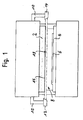
- eine schematische Frontansicht einer Gesenkbiegepresse, und
- Fig. 2a,b
- jeweils eine schematische Seitenansicht von Teilen dieser Gesenkbiegepresse in unterschiedlichen Phasen eines normalen Bearbeitungsvorgangs.
- Fig. 1
- a schematic front view of a Gesenkbiegepresse, and
- Fig. 2a, b
- each a schematic side view of parts of this press brake in different phases of a normal machining operation.
Die in Fig. 1 gezeigte Gesenkbiegepresse besitzt ein Oberwerkzeug bzw.
einen Pressbalken 2, das bzw. der zu einer Arbeitsbewegung vertikal nach
unten gegen ein Unterwerkzeug 4 angetrieben werden kann, um ein auf
dem Unterwerkzeug 4 aufliegendes Werkstück 6 zu biegen. Während
dieser Arbeitsbewegung wird ein Öffnungsspalt 8 zwischen dem Oberwerkzeug
2 und dem Werkstück 6 allmählich geschlossen.The press brake shown in Fig. 1 has an upper tool or
a
An den beiden Seiten des Pressbalkens 2 ist jeweils ein Haltearm 10 vorgesehen.
Die Haltearme 10 tragen eine Sendeeinrichtung 12 und eine
ortsauflösende Empfangseinrichtung 14, die Teile eines optoelektronischen
Sensors und zum Oberwerkzeug 2 ausgerichtet sind. Die Sendeeinrichtung
12 besitzt eine z.B. als LED oder Laserdiode ausgebildete Lichtquelle
mit einer Sendeoptik (in den Figuren nicht gezeigt), die das Sendelicht
der Lichtquelle zu einem Lichtstrahl 16 aufweitet. In meisten Anwendungsfällen
der Erfindung ist es sinnvoll, den Lichtstrahl 16 derart aufzuweiten,
dass z.B. auch Teile des Oberwerkzeugs 2 vom Lichtstrahl 16
erfasst werden (siehe auch Fig. 2a, b). Die Empfangseinrichtung 14 besitzt
einen rechteckigen, z.B. in CMOS-, CID-, CCD-Technik oder dergleichen
ausgebildeten Matrix-Empfänger, der von dem Lichtstrahl 16 beaufschlagt
wird und der so bemessen ist, dass der Lichtstrahl mit seinem vollen
Querschnitt auf den Empfänger auftrifft.On the two sides of the
Der Lichtstrahl 16 durchquert den Öffnungsspalt 8 unterhalb des Oberwerkzeugs
2. Der Umriss eines entsprechend aktivierten Teils der Empfangseinrichtung
14 definiert innerhalb des Lichtstrahls 16 ein volumenförmiges
Schutzfeld 18 zwischen dem Oberwerkzeug 2 und dem Unterwerkzeug
4, wie nachfolgend in Verbindung mit Fig. 2a und 2b noch
erläutert wird. Sobald eine Auswerte- und Steuereinrichtung des Sensors
(in den Figuren nicht gezeigt) eine Unterbrechung des Lichtstrahls 16
innerhalb des Schutzfelds 18 detektiert, löst sie einen Abschaltvorgang
zum Anhalten des Oberwerkzeugs 2 aus. Dadurch wird eine Bedienperson,
die beispielsweise das Werkstück 6 in den Öffnungsspalt 8 einführt
und dort fixiert, vor Verletzungen durch das Oberwerkzeug 2 geschützt.The
Nachfolgend wird anhand der Fig. 2a und 2b die Funktionsweise der
erfindungsgemäß ausgestatteten Gesenkbiegepresse gemäß Fig. 1, welche
mit einem gegenüber Fig. 1 stärker aufgeweiteten Lichtstrahl 16 arbeitet,
erläutert.Hereinafter, with reference to FIGS. 2a and 2b, the operation of the
According to the invention equipped Gesenkbiegepresse shown in FIG. 1, which
works with a relative to FIG. 1 more expanded
Fig. 2a und 2b zeigen jeweils das Oberwerkzeug 2, das Unterwerkzeug 4,
das darauf aufliegende Werkstück 6 und den im Querschnitt kreisrunden
Lichtstrahl 16 in einer schematischen Seitenansicht. 2a and 2b respectively show the
Die Empfangseinrichtung 14 mit ihrer Empfangsmatrix ist derart bemessen,
dass der in den Figuren 2a und 2b dargestellte Lichtstrahl 16 mit
seinem vollen Querschnitt auf die Empfangseinrichtung 14 auftrifft, so
dass mittels der Empfangsmatrix detektiert werden kann, ob der Lichtweg
zwischen Lichtsender 12 und Lichtempfänger 14 an einer beliebigen Stelle
des Lichtstrahls 16 unterbrochen ist. Diese Informationen, die von den
einzelnen Empfangselementen der Empfangsmatrix geliefert werden,
gelangen erfindungsgemäß zu einer Auswerte-Steuereinheit, welche diese
Informationen in unterschiedlicher Weise verarbeitet:The receiving
Diejenigen Empfangselemente, die dem in den Figuren 2a und 2b dargestellten,
rechteckigen, unterhalb des Oberwerkzeugs 2 angeordneten
Schutzfeld 20 zugeordnet sind, liefern Signale, die immer dann zu einem
Abschalten der Gesenkbiegepresse führen, wenn der Lichtstrahl 16 in
einem dem Schutzfeld 20 entsprechenden Teilbereich unterbrochen wird.
Das Schutzfeld 20 ist dabei innerhalb des Lichtstrahls 16 stationär angeordnet,
so dass sichergestellt ist, dass er sich immer direkt unterhalb des
Oberwerkzeugs 2 befindet, an welchem der optoelektronische Sensor 12,
14 angebracht ist.Those receiving elements which correspond to the one shown in FIGS. 2a and 2b,
rectangular, arranged below the
Zusätzlich zum Schutzfeld 20 werden bestimmte Empfangselemente der
Empfangseinrichtung 14 als Messfenster 22 definiert, von denen in den
Figuren 2a und 2b jeweils zwei Stück exemplarisch dargestellt sind. Die
von den Messfenstern 22 gelieferten Signale haben hinsichtlich der erläuterten
Abschaltfunktion keine Bedeutung und werden ausschließlich zu
einem Vermessen des bearbeiteten Werkstücks 6 verwendet.In addition to the
Zur Festlegung der Position der Messfenster 22 werden alle von der Empfangseinrichtung
14 gelieferten Signale mittels geeigneter Bildverarbeitungsalgorithmen
derart verarbeitet, dass Bereiche des Werkstücks 6, die
auf der Empfangseinrichtung 14 einen Schattenriss mit gerader Kontur
erzeugen, erkannt werden. Daraufhin werden die Messfenster 22 in solche
Bereiche der Empfangseinrichtung 14 verschoben, auf denen solche
Schattenrissbereiche mit vorzugsweise gerader Kontur abgebildet sind.To determine the position of the measuring
Im Bereich der Messfenster kann somit die Gestalt des Schattenrisses des
Werkstückes 6 ermittelt werden. Ebenso ist es beispielsweise möglich, den
Verlauf der Unterseite des Werkstücks 6 (siehe Pfeile A gemäß Figur 2a)
oder den Verlauf der Oberseite des Werkstücks 6 (siehe Pfeile B in Figur
2b) innerhalb der Messfenster 22 zu bestimmen.In the area of the measuring windows, the shape of the silhouette of the
Aus den bestimmten Verläufen von Oberseite, Unterseite oder Schattenriss
kann dann durch eine Verarbeitung der Signale der beiden Messfenster
22 der momentan durch die Gesenkbiegepresse erzeugte Biegewinkel
des Werkstücks 6 bestimmt werden.From the specific progressions of top, bottom or silhouette
can then by processing the signals of the two
Durch eine ständige Überprüfung der von der Empfangseinrichtung 14
gelieferten Signale dahingehend, wo sich Schattenrissbereiche des Werkstücks
6 mit vorzugsweise gerader Kontur gerade befinden, wird es möglich,
die Messfenster 22 mit fortschreitendem Biegeprozess "mitwandern"
zu lassen, so dass sich die Position der Messfenster 22 in verschiedenen
Phasen des Biegeprozesses verändert, wie dies die Figuren 2a und 2b
veranschaulichen. Bei Figur 2b ist der Biegeprozess weiter fortgeschritten
als bei Figur 2a. Durch die jeweils angepasste Position der Messfenster 22
kann in beiden Fällen jedoch ermittelt werden, welcher Biegewinkel am
Werkstück 6 gerade vorliegt. By a constant review of the receiving device 14th
supplied signals to where silhouettes of the
Erfindungsgemäß kann ein Vermessen des Werkstücks 6 über die Messfenster
22 sowie die Abschaltfunktion über das Schutzfeld 20 sowohl
gleichzeitig als auch alternierend durchgeführt werden. According to the invention, a measurement of the
- 22
- Oberwerkzeugupper tool
- 44
- Unterwerkzeuglower tool
- 66
- Werkstückworkpiece
- 88th
- Öffnungsspaltopening gap
- 1010
- Haltearmeholding arms
- 1212
- Sendeeinrichtungtransmitting device
- 1414
- Empfangseinrichtungreceiver
- 1616
- Lichtstrahlbeam of light
- 1818
- Schutzfeldprotection field
- 2020
- Schutzfeldprotection field
- 2222
- Messfenstermeasurement window
Claims (16)
dadurch gekennzeichnet , dass aus den von den lichtempfindlichen Elementen gelieferten Signalen Relativpositionen zwischen einzelnen Werkstück- oder Werkzeugbereichen oder auf einzelne Werkstück- oder Werkzeugbereiche bezogene Messwerte ermittelt werden.Method for securing a machine tool with a first tool part (2), which performs working movements in the direction of a second tool part (4), thereby performing a machining operation on a workpiece (6), wherein an opto-electronic sensor (12, 14) a volume-shaped protective field (18, 20) between the tool parts (2, 4) monitored by light by means of a transmitting device (12) along an opening between the tool parts (2, 4) formed opening gap (8) and detected by a receiving device (14) which a matrix of photosensitive elements, wherein stopping of the first tool part (2) occurs when individual or certain groups of the photosensitive elements do not receive light,
characterized in that from the signals supplied by the photosensitive elements relative positions between individual workpiece or tool areas or on individual workpiece or tool areas related measured values are determined.
dadurch gekennzeichnet , dass durch die Auswertung der von den lichtempfindlichen Elementen gelieferten Signale eine Bestimmung des Schattenrisses von Werkstücken (6) oder Werkzeugen erfolgt. Method according to claim 1,
characterized in that by the evaluation of the signals supplied by the photosensitive elements, a determination of the shadow contour of workpieces (6) or tools takes place.
dadurch gekennzeichnet , dass in Abhängigkeit von den ermittelten Relativpositionen oder Messwerten
characterized in that in dependence on the determined relative positions or measured values
dadurch gekennzeichnet , dass die Relativpositionen vor, während und/oder nach dem Bearbeitungsvorgang ermittelt werden.Method according to one of the preceding claims,
characterized in that the relative positions are determined before, during and / or after the machining operation.
dadurch gekennzeichnet , dass Gruppen benachbarter lichtempfindlicher Elemente als Messfenster (22) definiert und nur die von diesen Messfenstern (22) gelieferten Signale zur Ermittlung der Relativpositionen herangezogen werden.Method according to one of the preceding claims,
characterized in that groups of adjacent photosensitive elements are defined as measuring windows (22) and only the signals supplied by these measuring windows (22) are used to determine the relative positions.
dadurch gekennzeichnet , dass die Messfenster (22) während eines Bearbeitungsvorgangs innerhalb der Matrix verschoben oder in ihrer Größe und/oder Form verändert werden. Method according to claim 5,
characterized in that the measuring windows (22) are moved during a machining operation within the matrix or changed in size and / or shape.
dadurch gekennzeichnet , dass die Veränderung in Abhängigkeit von den ermittelten Relativpositionen oder Messwerten, von Betriebszuständen der Werkzeugmaschine und/oder von Eingaben einer Bedienperson erfolgt.Method according to claim 6,
characterized in that the change takes place as a function of the determined relative positions or measured values, operating states of the machine tool and / or inputs of an operator.
dadurch gekennzeichnet , dass mittels Bildverarbeitungsalgorithmen Bereiche des Werkstücks (6) mit geradem Konturverlauf bestimmt und die Messfenster (22) in diese Bereiche gelegt werden.Method according to one of the preceding claims,
characterized in that by means of image processing algorithms determined areas of the workpiece (6) with a straight contour and the measuring window (22) are placed in these areas.
dadurch gekennzeichnet , dass die Messfenster (22) in einer festen Relativposition zum ersten Werkzeugteil (2) positioniert sind oder positioniert werden.Method according to one of claims 5 to 8,
characterized in that the measuring windows (22) are positioned or positioned in a fixed relative position to the first tool part (2).
dadurch gekennzeichnet , dass die Auswerte- und Steuereinheit zusätzlich zur Ermittlung von Relativpositionen zwischen einzelnen Werkstück- oder Werkzeugbereichen oder von auf einzelne Werkstück- oder Werkzeugbereiche bezogenen Messwerten in Abhängigkeit von den durch die lichtempfindlichen Elemente gelieferten Signalen ausgelegt ist.Optoelectronic sensor as a protective device for securing a machine tool with a first tool part (2) for performing working movements in the direction of a second tool part (4) to perform a machining operation on a workpiece (6), wherein the sensor (12, 14) for monitoring a volumetric protective field (18, 20) between the tool parts (2, 4) a transmitting device (12) for emitting light along an opening gap (8) formed between the tool parts (2, 4) and a receiving device (14) comprising a matrix of photosensitive elements for detecting the emitted light, the sensor (12, 14) further having an evaluation and control unit for stopping the first tool part (2) when individual or certain groups of the photosensitive elements do not receive light,
characterized in that the evaluation and control unit is additionally designed for determining relative positions between individual workpiece or tool areas or measured values relating to individual workpiece or tool areas as a function of the signals supplied by the photosensitive elements.
dadurch gekennzeichnet , dass er zur Durchführung des Verfahrens nach einem der Ansprüche 1 bis 9 ausgebildet ist.Optoelectronic sensor according to claim 10,
characterized in that it is designed for carrying out the method according to one of claims 1 to 9.
dadurch gekennzeichnet , dass die Sendeeinrichtung (12) zur Aussendung eines parallelen Lichtbündels (16) ausgelegt ist.Optoelectronic sensor according to one of claims 10 or 11,
characterized in that the transmitting device (12) is designed to emit a parallel light beam (16).
dadurch gekennzeichnet , dass er in einer festen Relativposition zum ersten (2) oder zum zweiten (4) Werkzeugteil an der Werkzeugmaschine angebracht ist.Optoelectronic sensor according to one of claims 10 to 12,
characterized in that it is mounted in a fixed relative position to the first (2) or to the second (4) tool part on the machine tool.
dadurch gekennzeichnet , dass die Auswerte- und Steuereinheit und die Empfangseinrichtung (14) miteinander gekoppelt und insbesondere in einem gemeinsamen Gehäuse untergebracht sind. Optoelectronic sensor according to one of claims 10 to 13,
characterized in that the evaluation and control unit and the receiving device (14) are coupled together and housed in particular in a common housing.
dadurch gekennzeichnet , dass die Auswerte- und Steuereinheit Datenausgänge zur Abgabe von Abschaltsignalen und von die ermittelten Relativpositionen oder Messwerte beschreibenden Daten aufweist.Optoelectronic sensor according to one of claims 10 to 14,
characterized in that the evaluation and control unit has data outputs for the delivery of shutdown signals and of the determined relative positions or measured values descriptive data.
dadurch gekennzeichnet , dass die Werkzeugmaschine als Gesenk- oder Abkantpresse, Biege-, Schneid- oder Stanzmaschine ausgebildet ist.Optoelectronic sensor according to one of claims 10 to 15,
characterized in that the machine tool is designed as a swaging or press brake, bending, cutting or punching machine.
Applications Claiming Priority (2)
| Application Number | Priority Date | Filing Date | Title |
|---|---|---|---|
| DE200410020024 DE102004020024A1 (en) | 2004-04-23 | 2004-04-23 | Method for securing a machine tool and optoelectronic sensor for carrying out such a method |
| DE102004020024 | 2004-04-23 |
Publications (5)
| Publication Number | Publication Date |
|---|---|
| EP1589279A2 true EP1589279A2 (en) | 2005-10-26 |
| EP1589279A3 EP1589279A3 (en) | 2005-11-30 |
| EP1589279B1 EP1589279B1 (en) | 2007-01-10 |
| EP1589279B2 EP1589279B2 (en) | 2013-10-23 |
| EP1589279B9 EP1589279B9 (en) | 2014-02-26 |
Family
ID=34934182
Family Applications (1)
| Application Number | Title | Priority Date | Filing Date |
|---|---|---|---|
| EP20050005261 Expired - Lifetime EP1589279B9 (en) | 2004-04-23 | 2005-03-10 | Safety method for a machine tool and optoelectronic sensor for carrying out such a method |
Country Status (4)
| Country | Link |
|---|---|
| US (1) | US7448242B2 (en) |
| EP (1) | EP1589279B9 (en) |
| JP (1) | JP2005319517A (en) |
| DE (2) | DE102004020024A1 (en) |
Cited By (9)
| Publication number | Priority date | Publication date | Assignee | Title |
|---|---|---|---|---|
| EP1914019A1 (en) * | 2006-10-18 | 2008-04-23 | Warcom S.p.A. | Press brake and related workpiece bending procedure |
| WO2008002555A3 (en) * | 2006-06-26 | 2008-06-05 | Qualex Mfg Lc | Method and apparatus for detecting unsafe conditions |
| EP2053538A1 (en) | 2007-10-25 | 2009-04-29 | Sick Ag | Securing a surveillance area and visual support for automatic processing |
| DE102009050850A1 (en) | 2009-10-19 | 2011-04-21 | Daimler Ag | Method for monitoring sections of automatically working machine utilized for assembling motor vehicle, involves detecting objects based on analysis, where assembly objects in standard sections are detected by non-safety relevant analysis |
| US8101917B2 (en) | 2006-06-26 | 2012-01-24 | Qualex Manufacturing Llc | Method and apparatus for detecting unsafe conditions |
| US8314393B2 (en) | 2008-12-23 | 2012-11-20 | Qualex Manufacturing, Lc | Method and apparatus for detecting unsafe conditions |
| EP2633925A1 (en) * | 2012-03-02 | 2013-09-04 | Fiessler Elektronik GmbH & Co. KG | Bending machine with a safety device and method for operating such a machine |
| CN104019746A (en) * | 2014-06-20 | 2014-09-03 | 中国石油大学(北京) | Measurement device and method for fracture shapes after physical model samples are fractured |
| DE202018103290U1 (en) | 2018-06-12 | 2019-09-16 | Pilz Gmbh & Co. Kg | Safety device for a machine, in particular for a bending press |
Families Citing this family (26)
| Publication number | Priority date | Publication date | Assignee | Title |
|---|---|---|---|---|
| US8692877B2 (en) * | 2005-06-20 | 2014-04-08 | Lazer Safe Pty Ltd | Imaging and safety system and method for an industrial machine |
| WO2006135961A1 (en) * | 2005-06-20 | 2006-12-28 | Lazer Safe Pty Ltd | Imaging and safety system and method for an industrial machine |
| AT502038B1 (en) * | 2005-07-06 | 2007-01-15 | Trumpf Maschinen Austria Gmbh | SAFETY DEVICE FOR AN ABKANTPRESSE AND A LAMELLENWERKZEUG |
| JP4798770B2 (en) * | 2005-12-27 | 2011-10-19 | 株式会社アマダ | Bending machine |
| JP4877734B2 (en) * | 2006-01-10 | 2012-02-15 | 株式会社アマダ | Bending machine |
| JP4993556B2 (en) * | 2006-01-18 | 2012-08-08 | 株式会社アマダ | Bending machine |
| JP5044994B2 (en) * | 2006-05-30 | 2012-10-10 | 株式会社日立製作所 | Processing machine with safety device to prevent pinching |
| CN100582680C (en) * | 2006-12-05 | 2010-01-20 | 鸿富锦精密工业(深圳)有限公司 | Detector |
| DE102007006306A1 (en) | 2007-01-30 | 2008-07-31 | Pilz Gmbh & Co. Kg | Safety device for e.g. die bending press machine, has light emitter producing light rays, with light source having predominantly incoherent radiation, and light receiver with image optics having focus and aperture arranged in focus |
| DE202008003444U1 (en) | 2007-03-05 | 2008-07-10 | Pilz Gmbh & Co. Kg | Safety device for securing a machine |
| DE502008002818D1 (en) | 2008-07-25 | 2011-04-21 | Fiessler Elektronik Gmbh & Co Kg | reshaping |
| DE202010004438U1 (en) | 2010-03-29 | 2011-08-11 | Pilz Gmbh & Co. Kg | Safety device for a machine in which a first machine part performs a working movement against a second machine part |
| DE202010017960U1 (en) | 2010-09-20 | 2013-04-17 | Bystronic Laser Ag | Protection system for operating safety on machines, in particular press bending presses |
| CN102284885A (en) * | 2011-07-28 | 2011-12-21 | 常州昌隆机床制造有限公司 | Totally enclosed type protective structure of numerical control gantry machine tool |
| CN103084512A (en) * | 2013-01-25 | 2013-05-08 | 丁松炎 | Bending machine photoelectric protection safety device |
| KR102138512B1 (en) * | 2013-03-26 | 2020-07-28 | 엘지전자 주식회사 | Display Device And Controlling Method Thereof |
| CN103691840B (en) * | 2014-01-10 | 2016-05-11 | 中山广都机电有限公司 | Safety protection device of bending machine |
| JP6243954B2 (en) * | 2016-04-14 | 2017-12-06 | 株式会社アマダホールディングス | Press brake safety device |
| AT518993B1 (en) * | 2016-11-18 | 2018-03-15 | Trumpf Maschinen Austria Gmbh & Co Kg | Method for operating a bending machine |
| CN106975691A (en) * | 2017-05-31 | 2017-07-25 | 成都亨通兆业精密机械有限公司 | Production and processing device for regulator cubicle section bar |
| CN107081373A (en) * | 2017-05-31 | 2017-08-22 | 成都亨通兆业精密机械有限公司 | Quick fixing means for aluminium drilling operating |
| US10197219B1 (en) | 2017-08-04 | 2019-02-05 | Jason Boyer | Secondary light curtain for detecting crush zone intrusion in a secondary process and associated method for use |
| CN107900139A (en) * | 2017-12-29 | 2018-04-13 | 北京简易科技有限公司 | A kind of press machine and strip bend detection method |
| CN110456423B (en) * | 2018-05-07 | 2024-03-19 | 特鲁普机械奥地利有限公司及两合公司 | Cutting chip identification for bending units |
| CN111570660B (en) * | 2020-06-05 | 2021-09-17 | 山东穆柯传感器有限公司 | Intelligent silicon optical matrix bending machine protection device and protection method |
| CN115780568B (en) * | 2023-02-13 | 2023-04-18 | 山东新合源热传输科技有限公司 | Emergency alarm device for hardware stamping |
Family Cites Families (29)
| Publication number | Priority date | Publication date | Assignee | Title |
|---|---|---|---|---|
| US4166369A (en) † | 1978-04-06 | 1979-09-04 | Kabushiki Kaisha Komatsu Seisakusho | Safety device for press brake |
| US4249074A (en) * | 1978-06-06 | 1981-02-03 | Xenex Corporation | Intrusion detector for press brake |
| US4430879A (en) † | 1981-06-12 | 1984-02-14 | Hurco Manufacturing Company, Inc. | Apparatus for controlling a press brake |
| US4660703A (en) * | 1983-11-07 | 1987-04-28 | Nevio Filcich | Method and apparatus for machine safety |
| EP0166351A3 (en) † | 1984-06-27 | 1986-09-17 | Arnold Stucki | Device at a machine for deformation work of sheet metals |
| US4709432A (en) * | 1984-10-01 | 1987-12-01 | Barrick Fred A | Combination device for applying tire chains and mounting a jack |
| CH665364A5 (en) * | 1985-10-30 | 1988-05-13 | Cybelec Sa | DEVICE FOR AUTOMATICALLY CONTROLLING THE FOLDING OPERATION DURING FOLDING WITH A BENDING PRESS. |
| CH669131A5 (en) † | 1986-10-14 | 1989-02-28 | Cybelec Sa | SAFETY DEVICE OF A MACHINE TOOL. |
| JP2818441B2 (en) * | 1989-07-20 | 1998-10-30 | 株式会社アマダ | Bending machine |
| JPH0792193B2 (en) * | 1989-10-26 | 1995-10-09 | 国際制御株式会社 | Light safety device for press machine |
| AU667057B2 (en) * | 1991-10-18 | 1996-03-07 | Thomas John Appleyard | Brake press safety apparatus |
| DE4422497C2 (en) * | 1994-06-28 | 1996-06-05 | Leuze Electronic Gmbh & Co | Device and method for optoelectronic detection of objects |
| JP3093671B2 (en) * | 1997-02-14 | 2000-10-03 | 国際制御株式会社 | Beam safety device |
| DE19825829C2 (en) † | 1998-06-10 | 2000-07-27 | Leica Microsystems | Method for determining the distance P of an edge of a structural element on a substrate |
| DE19828000C2 (en) * | 1998-06-24 | 2000-06-21 | Schmersal Eot Gmbh & Co Kg | Method for optoelectronic monitoring of a protected area |
| DE19835033C1 (en) * | 1998-07-23 | 1999-11-04 | Bellheimer Metallwerk Gmbh | Load lifting elevator frame |
| US6660993B2 (en) * | 1999-04-16 | 2003-12-09 | Tirops Safety-Technology Inc. | Safety apparatus and protection method for machines |
| DE19938639B4 (en) † | 1999-08-14 | 2006-08-24 | Pilz Gmbh & Co. Kg | Device for securing a danger zone, in particular the danger zone of an automated machine |
| DE10000287B4 (en) * | 2000-01-07 | 2004-02-12 | Leuze Lumiflex Gmbh + Co. Kg | Device and method for monitoring a detection area on a work equipment |
| DE10027156A1 (en) * | 2000-05-31 | 2001-12-06 | Fiessler Elektronik Ohg | Protection device for machines, such as press brakes, cutting machines, punching machines or the like |
| US6389860B1 (en) * | 2000-08-11 | 2002-05-21 | Lion Machinery, Inc. | Control system for a press brake |
| DE20102192U1 (en) * | 2001-02-08 | 2001-06-21 | Argast, Martin, 72584 Hülben | Angle encoder |
| DE10114784A1 (en) * | 2001-03-26 | 2002-10-10 | Sick Ag | Device for monitoring a protective field |
| DE10123562A1 (en) * | 2001-05-15 | 2002-11-21 | Fiessler Elektronik Ohg | Protection device for machines, such as press brakes, cutting machines, punching machines or the like |
| DE10143505B4 (en) * | 2001-09-05 | 2010-07-08 | Sick Ag | Safety procedure and optoelectronic sensor |
| DE10152543A1 (en) * | 2001-10-24 | 2003-05-08 | Sick Ag | Method and device for controlling a safety-relevant function of a machine |
| EP1319886B1 (en) * | 2001-12-13 | 2005-12-28 | Fiessler Elektronik GmbH & Co. KG | Protective device for machines such as bending presses, cutting machines, punching machines or the like |
| JP4511345B2 (en) * | 2002-06-11 | 2010-07-28 | デイビス,ケヴィン,ステファン | Safety system |
| DE20217426U1 (en) * | 2002-11-05 | 2003-01-16 | Pilz GmbH & Co., 73760 Ostfildern | Safety device for a machine, in particular for a bending press |
-
2004
- 2004-04-23 DE DE200410020024 patent/DE102004020024A1/en not_active Withdrawn
-
2005
- 2005-03-10 DE DE200550000296 patent/DE502005000296D1/en not_active Expired - Lifetime
- 2005-03-10 EP EP20050005261 patent/EP1589279B9/en not_active Expired - Lifetime
- 2005-04-20 JP JP2005121861A patent/JP2005319517A/en active Pending
- 2005-04-21 US US11/111,214 patent/US7448242B2/en not_active Expired - Fee Related
Non-Patent Citations (1)
| Title |
|---|
| None |
Cited By (13)
| Publication number | Priority date | Publication date | Assignee | Title |
|---|---|---|---|---|
| US8101917B2 (en) | 2006-06-26 | 2012-01-24 | Qualex Manufacturing Llc | Method and apparatus for detecting unsafe conditions |
| WO2008002555A3 (en) * | 2006-06-26 | 2008-06-05 | Qualex Mfg Lc | Method and apparatus for detecting unsafe conditions |
| US7439512B2 (en) | 2006-06-26 | 2008-10-21 | Qualex Manufacturing Llc | Method and apparatus for detecting unsafe conditions |
| CN101528382B (en) * | 2006-06-26 | 2012-10-03 | 夸里科斯制造有限公司 | Method and apparatus for detecting unsafe conditions |
| EP1914019A1 (en) * | 2006-10-18 | 2008-04-23 | Warcom S.p.A. | Press brake and related workpiece bending procedure |
| EP2053538A1 (en) | 2007-10-25 | 2009-04-29 | Sick Ag | Securing a surveillance area and visual support for automatic processing |
| US8314393B2 (en) | 2008-12-23 | 2012-11-20 | Qualex Manufacturing, Lc | Method and apparatus for detecting unsafe conditions |
| DE102009050850A1 (en) | 2009-10-19 | 2011-04-21 | Daimler Ag | Method for monitoring sections of automatically working machine utilized for assembling motor vehicle, involves detecting objects based on analysis, where assembly objects in standard sections are detected by non-safety relevant analysis |
| DE102009050850B4 (en) | 2009-10-19 | 2019-01-03 | Pilz Gmbh & Co. Kg | Method and device for monitoring protection and standard areas |
| EP2633925A1 (en) * | 2012-03-02 | 2013-09-04 | Fiessler Elektronik GmbH & Co. KG | Bending machine with a safety device and method for operating such a machine |
| CN104019746A (en) * | 2014-06-20 | 2014-09-03 | 中国石油大学(北京) | Measurement device and method for fracture shapes after physical model samples are fractured |
| CN104019746B (en) * | 2014-06-20 | 2017-01-25 | 中国石油大学(北京) | Measurement device and method for fracture shapes after physical model samples are fractured |
| DE202018103290U1 (en) | 2018-06-12 | 2019-09-16 | Pilz Gmbh & Co. Kg | Safety device for a machine, in particular for a bending press |
Also Published As
| Publication number | Publication date |
|---|---|
| DE502005000296D1 (en) | 2007-02-22 |
| EP1589279B1 (en) | 2007-01-10 |
| EP1589279A3 (en) | 2005-11-30 |
| JP2005319517A (en) | 2005-11-17 |
| DE102004020024A1 (en) | 2005-11-10 |
| US20050235790A1 (en) | 2005-10-27 |
| EP1589279B9 (en) | 2014-02-26 |
| US7448242B2 (en) | 2008-11-11 |
| EP1589279B2 (en) | 2013-10-23 |
Similar Documents
| Publication | Publication Date | Title |
|---|---|---|
| EP1589279B2 (en) | Safety method for a machine tool and optoelectronic sensor for carrying out such a method | |
| EP2076357B1 (en) | Machine tool monitoring device | |
| EP3038786B1 (en) | Method of determining deviations of the actual position of a laser machining head from the target position thereof and laser machining device for carrying out the method | |
| EP3321557B1 (en) | Deformation device and method for operating a deformation device | |
| EP1970667B1 (en) | Sheet metal working machine with a device for inspecting a perforation in a workpiece as results of an operation on the workpiece | |
| AT518993B1 (en) | Method for operating a bending machine | |
| DE10143505B4 (en) | Safety procedure and optoelectronic sensor | |
| DE10327388B4 (en) | guard | |
| EP1437542B1 (en) | Light barrier and method for its adjustment | |
| DE2734804C2 (en) | Method for setting an output line within an automatic control for a machine tool and positioning device for a machine tool for carrying out the method | |
| DE10309399A1 (en) | Security method and optoelectronic sensor | |
| AT522419B1 (en) | Measuring device for determining the bending angle | |
| EP3566793B1 (en) | Slug detection for bending cells | |
| EP2227348B1 (en) | Monitoring unit for a monitoring region in a machine tool | |
| EP1746335B1 (en) | Method for securing a bending machine and optoelectronic sensor for carrying out the method | |
| AT520726B1 (en) | Method for monitoring a production plant and manufacturing plant with a security system | |
| DE202010017960U1 (en) | Protection system for operating safety on machines, in particular press bending presses | |
| AT518894A4 (en) | Bending machine with a bending information display device | |
| WO2020023988A1 (en) | Method for operating a press brake | |
| EP2431650A1 (en) | Safety system for operational safety for machines, in particular folding presses | |
| EP1589355B1 (en) | Method to adjust a security system and an optoelectronic security system | |
| DE3940246C2 (en) | ||
| DE2817787C2 (en) | ||
| EP0950938B1 (en) | Method and device for quality control | |
| EP0607498A1 (en) | Method for operating a cutting press and cutting press |
Legal Events
| Date | Code | Title | Description |
|---|---|---|---|
| PUAI | Public reference made under article 153(3) epc to a published international application that has entered the european phase |
Free format text: ORIGINAL CODE: 0009012 |
|
| PUAL | Search report despatched |
Free format text: ORIGINAL CODE: 0009013 |
|
| AK | Designated contracting states |
Kind code of ref document: A2 Designated state(s): AT BE BG CH CY CZ DE DK EE ES FI FR GB GR HU IE IS IT LI LT LU MC NL PL PT RO SE SI SK TR |
|
| AX | Request for extension of the european patent |
Extension state: AL BA HR LV MK YU |
|
| AK | Designated contracting states |
Kind code of ref document: A3 Designated state(s): AT BE BG CH CY CZ DE DK EE ES FI FR GB GR HU IE IS IT LI LT LU MC NL PL PT RO SE SI SK TR |
|
| AX | Request for extension of the european patent |
Extension state: AL BA HR LV MK YU |
|
| RIC1 | Information provided on ipc code assigned before grant |
Ipc: 7B 21D 55/00 B Ipc: 7F 16P 3/04 B Ipc: 7B 30B 15/28 B Ipc: 7F 16P 3/14 A |
|
| 17P | Request for examination filed |
Effective date: 20060420 |
|
| GRAP | Despatch of communication of intention to grant a patent |
Free format text: ORIGINAL CODE: EPIDOSNIGR1 |
|
| AKX | Designation fees paid |
Designated state(s): AT BE BG CH CY CZ DE DK EE ES FI FR GB GR HU IE IS IT LI LT LU MC NL PL PT RO SE SI SK TR |
|
| GRAS | Grant fee paid |
Free format text: ORIGINAL CODE: EPIDOSNIGR3 |
|
| GRAA | (expected) grant |
Free format text: ORIGINAL CODE: 0009210 |
|
| AK | Designated contracting states |
Kind code of ref document: B1 Designated state(s): AT BE BG CH CY CZ DE DK EE ES FI FR GB GR HU IE IS IT LI LT LU MC NL PL PT RO SE SI SK TR |
|
| PG25 | Lapsed in a contracting state [announced via postgrant information from national office to epo] |
Ref country code: DK Free format text: LAPSE BECAUSE OF FAILURE TO SUBMIT A TRANSLATION OF THE DESCRIPTION OR TO PAY THE FEE WITHIN THE PRESCRIBED TIME-LIMIT Effective date: 20070110 Ref country code: SI Free format text: LAPSE BECAUSE OF FAILURE TO SUBMIT A TRANSLATION OF THE DESCRIPTION OR TO PAY THE FEE WITHIN THE PRESCRIBED TIME-LIMIT Effective date: 20070110 Ref country code: NL Free format text: LAPSE BECAUSE OF FAILURE TO SUBMIT A TRANSLATION OF THE DESCRIPTION OR TO PAY THE FEE WITHIN THE PRESCRIBED TIME-LIMIT Effective date: 20070110 Ref country code: IE Free format text: LAPSE BECAUSE OF FAILURE TO SUBMIT A TRANSLATION OF THE DESCRIPTION OR TO PAY THE FEE WITHIN THE PRESCRIBED TIME-LIMIT Effective date: 20070110 Ref country code: PL Free format text: LAPSE BECAUSE OF FAILURE TO SUBMIT A TRANSLATION OF THE DESCRIPTION OR TO PAY THE FEE WITHIN THE PRESCRIBED TIME-LIMIT Effective date: 20070110 Ref country code: FI Free format text: LAPSE BECAUSE OF FAILURE TO SUBMIT A TRANSLATION OF THE DESCRIPTION OR TO PAY THE FEE WITHIN THE PRESCRIBED TIME-LIMIT Effective date: 20070110 |
|
| REG | Reference to a national code |
Ref country code: GB Ref legal event code: FG4D Free format text: NOT ENGLISH |
|
| RAP2 | Party data changed (patent owner data changed or rights of a patent transferred) |
Owner name: SICK AG |
|
| REG | Reference to a national code |
Ref country code: IE Ref legal event code: FG4D Free format text: LANGUAGE OF EP DOCUMENT: GERMAN |
|
| REF | Corresponds to: |
Ref document number: 502005000296 Country of ref document: DE Date of ref document: 20070222 Kind code of ref document: P |
|
| GBT | Gb: translation of ep patent filed (gb section 77(6)(a)/1977) |
Effective date: 20070222 |
|
| NLT2 | Nl: modifications (of names), taken from the european patent patent bulletin |
Owner name: SICK AG Effective date: 20070214 |
|
| PG25 | Lapsed in a contracting state [announced via postgrant information from national office to epo] |
Ref country code: BG Free format text: LAPSE BECAUSE OF FAILURE TO SUBMIT A TRANSLATION OF THE DESCRIPTION OR TO PAY THE FEE WITHIN THE PRESCRIBED TIME-LIMIT Effective date: 20070410 Ref country code: SE Free format text: LAPSE BECAUSE OF FAILURE TO SUBMIT A TRANSLATION OF THE DESCRIPTION OR TO PAY THE FEE WITHIN THE PRESCRIBED TIME-LIMIT Effective date: 20070410 |
|
| PG25 | Lapsed in a contracting state [announced via postgrant information from national office to epo] |
Ref country code: ES Free format text: LAPSE BECAUSE OF FAILURE TO SUBMIT A TRANSLATION OF THE DESCRIPTION OR TO PAY THE FEE WITHIN THE PRESCRIBED TIME-LIMIT Effective date: 20070421 |
|
| PG25 | Lapsed in a contracting state [announced via postgrant information from national office to epo] |
Ref country code: IS Free format text: LAPSE BECAUSE OF FAILURE TO SUBMIT A TRANSLATION OF THE DESCRIPTION OR TO PAY THE FEE WITHIN THE PRESCRIBED TIME-LIMIT Effective date: 20070510 |
|
| PG25 | Lapsed in a contracting state [announced via postgrant information from national office to epo] |
Ref country code: PT Free format text: LAPSE BECAUSE OF FAILURE TO SUBMIT A TRANSLATION OF THE DESCRIPTION OR TO PAY THE FEE WITHIN THE PRESCRIBED TIME-LIMIT Effective date: 20070611 |
|
| NLV1 | Nl: lapsed or annulled due to failure to fulfill the requirements of art. 29p and 29m of the patents act | ||
| ET | Fr: translation filed | ||
| REG | Reference to a national code |
Ref country code: IE Ref legal event code: FD4D |
|
| PLBI | Opposition filed |
Free format text: ORIGINAL CODE: 0009260 |
|
| PLAX | Notice of opposition and request to file observation + time limit sent |
Free format text: ORIGINAL CODE: EPIDOSNOBS2 |
|
| 26 | Opposition filed |
Opponent name: PILZ GMBH & CO. KG Effective date: 20071009 |
|
| PG25 | Lapsed in a contracting state [announced via postgrant information from national office to epo] |
Ref country code: SK Free format text: LAPSE BECAUSE OF FAILURE TO SUBMIT A TRANSLATION OF THE DESCRIPTION OR TO PAY THE FEE WITHIN THE PRESCRIBED TIME-LIMIT Effective date: 20070110 |
|
| BERE | Be: lapsed |
Owner name: SICK A.G. Effective date: 20070331 |
|
| PG25 | Lapsed in a contracting state [announced via postgrant information from national office to epo] |
Ref country code: RO Free format text: LAPSE BECAUSE OF FAILURE TO SUBMIT A TRANSLATION OF THE DESCRIPTION OR TO PAY THE FEE WITHIN THE PRESCRIBED TIME-LIMIT Effective date: 20070110 Ref country code: BE Free format text: LAPSE BECAUSE OF NON-PAYMENT OF DUE FEES Effective date: 20070331 Ref country code: CZ Free format text: LAPSE BECAUSE OF FAILURE TO SUBMIT A TRANSLATION OF THE DESCRIPTION OR TO PAY THE FEE WITHIN THE PRESCRIBED TIME-LIMIT Effective date: 20070110 |
|
| PG25 | Lapsed in a contracting state [announced via postgrant information from national office to epo] |
Ref country code: MC Free format text: LAPSE BECAUSE OF NON-PAYMENT OF DUE FEES Effective date: 20070331 |
|
| PG25 | Lapsed in a contracting state [announced via postgrant information from national office to epo] |
Ref country code: LT Free format text: LAPSE BECAUSE OF FAILURE TO SUBMIT A TRANSLATION OF THE DESCRIPTION OR TO PAY THE FEE WITHIN THE PRESCRIBED TIME-LIMIT Effective date: 20070110 |
|
| PLBB | Reply of patent proprietor to notice(s) of opposition received |
Free format text: ORIGINAL CODE: EPIDOSNOBS3 |
|
| PG25 | Lapsed in a contracting state [announced via postgrant information from national office to epo] |
Ref country code: GR Free format text: LAPSE BECAUSE OF FAILURE TO SUBMIT A TRANSLATION OF THE DESCRIPTION OR TO PAY THE FEE WITHIN THE PRESCRIBED TIME-LIMIT Effective date: 20070411 |
|
| PG25 | Lapsed in a contracting state [announced via postgrant information from national office to epo] |
Ref country code: AT Free format text: LAPSE BECAUSE OF NON-PAYMENT OF DUE FEES Effective date: 20070310 |
|
| PLAB | Opposition data, opponent's data or that of the opponent's representative modified |
Free format text: ORIGINAL CODE: 0009299OPPO |
|
| PG25 | Lapsed in a contracting state [announced via postgrant information from national office to epo] |
Ref country code: EE Free format text: LAPSE BECAUSE OF FAILURE TO SUBMIT A TRANSLATION OF THE DESCRIPTION OR TO PAY THE FEE WITHIN THE PRESCRIBED TIME-LIMIT Effective date: 20070110 |
|
| APBM | Appeal reference recorded |
Free format text: ORIGINAL CODE: EPIDOSNREFNO |
|
| APBP | Date of receipt of notice of appeal recorded |
Free format text: ORIGINAL CODE: EPIDOSNNOA2O |
|
| APAH | Appeal reference modified |
Free format text: ORIGINAL CODE: EPIDOSCREFNO |
|
| APAW | Appeal reference deleted |
Free format text: ORIGINAL CODE: EPIDOSDREFNO |
|
| APBM | Appeal reference recorded |
Free format text: ORIGINAL CODE: EPIDOSNREFNO |
|
| APBP | Date of receipt of notice of appeal recorded |
Free format text: ORIGINAL CODE: EPIDOSNNOA2O |
|
| PG25 | Lapsed in a contracting state [announced via postgrant information from national office to epo] |
Ref country code: CY Free format text: LAPSE BECAUSE OF FAILURE TO SUBMIT A TRANSLATION OF THE DESCRIPTION OR TO PAY THE FEE WITHIN THE PRESCRIBED TIME-LIMIT Effective date: 20070110 |
|
| APBQ | Date of receipt of statement of grounds of appeal recorded |
Free format text: ORIGINAL CODE: EPIDOSNNOA3O |
|
| PG25 | Lapsed in a contracting state [announced via postgrant information from national office to epo] |
Ref country code: LU Free format text: LAPSE BECAUSE OF NON-PAYMENT OF DUE FEES Effective date: 20070310 |
|
| PG25 | Lapsed in a contracting state [announced via postgrant information from national office to epo] |
Ref country code: HU Free format text: LAPSE BECAUSE OF FAILURE TO SUBMIT A TRANSLATION OF THE DESCRIPTION OR TO PAY THE FEE WITHIN THE PRESCRIBED TIME-LIMIT Effective date: 20070711 |
|
| PGFP | Annual fee paid to national office [announced via postgrant information from national office to epo] |
Ref country code: TR Payment date: 20120305 Year of fee payment: 8 |
|
| PGFP | Annual fee paid to national office [announced via postgrant information from national office to epo] |
Ref country code: IT Payment date: 20120324 Year of fee payment: 8 |
|
| APBU | Appeal procedure closed |
Free format text: ORIGINAL CODE: EPIDOSNNOA9O |
|
| PGFP | Annual fee paid to national office [announced via postgrant information from national office to epo] |
Ref country code: CH Payment date: 20130319 Year of fee payment: 9 Ref country code: GB Payment date: 20130318 Year of fee payment: 9 Ref country code: FR Payment date: 20130329 Year of fee payment: 9 |
|
| PUAH | Patent maintained in amended form |
Free format text: ORIGINAL CODE: 0009272 |
|
| STAA | Information on the status of an ep patent application or granted ep patent |
Free format text: STATUS: PATENT MAINTAINED AS AMENDED |
|
| 27A | Patent maintained in amended form |
Effective date: 20131023 |
|
| AK | Designated contracting states |
Kind code of ref document: B2 Designated state(s): AT BE BG CH CY CZ DE DK EE ES FI FR GB GR HU IE IS IT LI LT LU MC NL PL PT RO SE SI SK TR |
|
| REG | Reference to a national code |
Ref country code: CH Ref legal event code: AELC |
|
| REG | Reference to a national code |
Ref country code: DE Ref legal event code: R102 Ref document number: 502005000296 Country of ref document: DE Effective date: 20131023 |
|
| REG | Reference to a national code |
Ref country code: CH Ref legal event code: PL |
|
| GBPC | Gb: european patent ceased through non-payment of renewal fee |
Effective date: 20140310 |
|
| REG | Reference to a national code |
Ref country code: FR Ref legal event code: ST Effective date: 20141128 |
|
| PG25 | Lapsed in a contracting state [announced via postgrant information from national office to epo] |
Ref country code: CH Free format text: LAPSE BECAUSE OF NON-PAYMENT OF DUE FEES Effective date: 20140331 Ref country code: LI Free format text: LAPSE BECAUSE OF NON-PAYMENT OF DUE FEES Effective date: 20140331 Ref country code: GB Free format text: LAPSE BECAUSE OF NON-PAYMENT OF DUE FEES Effective date: 20140310 Ref country code: FR Free format text: LAPSE BECAUSE OF NON-PAYMENT OF DUE FEES Effective date: 20140331 |
|
| PG25 | Lapsed in a contracting state [announced via postgrant information from national office to epo] |
Ref country code: IT Free format text: LAPSE BECAUSE OF NON-PAYMENT OF DUE FEES Effective date: 20140310 |
|
| PGFP | Annual fee paid to national office [announced via postgrant information from national office to epo] |
Ref country code: DE Payment date: 20150324 Year of fee payment: 11 |
|
| REG | Reference to a national code |
Ref country code: DE Ref legal event code: R119 Ref document number: 502005000296 Country of ref document: DE |
|
| PG25 | Lapsed in a contracting state [announced via postgrant information from national office to epo] |
Ref country code: DE Free format text: LAPSE BECAUSE OF NON-PAYMENT OF DUE FEES Effective date: 20161001 |
|
| PG25 | Lapsed in a contracting state [announced via postgrant information from national office to epo] |
Ref country code: TR Free format text: LAPSE BECAUSE OF NON-PAYMENT OF DUE FEES Effective date: 20140310 |