EP1589355B1 - Method to adjust a security system and an optoelectronic security system - Google Patents
Method to adjust a security system and an optoelectronic security system Download PDFInfo
- Publication number
- EP1589355B1 EP1589355B1 EP05003350A EP05003350A EP1589355B1 EP 1589355 B1 EP1589355 B1 EP 1589355B1 EP 05003350 A EP05003350 A EP 05003350A EP 05003350 A EP05003350 A EP 05003350A EP 1589355 B1 EP1589355 B1 EP 1589355B1
- Authority
- EP
- European Patent Office
- Prior art keywords
- alignment
- light
- receiver
- light beam
- safety device
- Prior art date
- Legal status (The legal status is an assumption and is not a legal conclusion. Google has not performed a legal analysis and makes no representation as to the accuracy of the status listed.)
- Not-in-force
Links
Images


Classifications
-
- G—PHYSICS
- G01—MEASURING; TESTING
- G01V—GEOPHYSICS; GRAVITATIONAL MEASUREMENTS; DETECTING MASSES OR OBJECTS; TAGS
- G01V8/00—Prospecting or detecting by optical means
- G01V8/10—Detecting, e.g. by using light barriers
- G01V8/20—Detecting, e.g. by using light barriers using multiple transmitters or receivers
-
- F—MECHANICAL ENGINEERING; LIGHTING; HEATING; WEAPONS; BLASTING
- F16—ENGINEERING ELEMENTS AND UNITS; GENERAL MEASURES FOR PRODUCING AND MAINTAINING EFFECTIVE FUNCTIONING OF MACHINES OR INSTALLATIONS; THERMAL INSULATION IN GENERAL
- F16P—SAFETY DEVICES IN GENERAL; SAFETY DEVICES FOR PRESSES
- F16P3/00—Safety devices acting in conjunction with the control or operation of a machine; Control arrangements requiring the simultaneous use of two or more parts of the body
- F16P3/12—Safety devices acting in conjunction with the control or operation of a machine; Control arrangements requiring the simultaneous use of two or more parts of the body with means, e.g. feelers, which in case of the presence of a body part of a person in or near the danger zone influence the control or operation of the machine
- F16P3/14—Safety devices acting in conjunction with the control or operation of a machine; Control arrangements requiring the simultaneous use of two or more parts of the body with means, e.g. feelers, which in case of the presence of a body part of a person in or near the danger zone influence the control or operation of the machine the means being photocells or other devices sensitive without mechanical contact
- F16P3/144—Safety devices acting in conjunction with the control or operation of a machine; Control arrangements requiring the simultaneous use of two or more parts of the body with means, e.g. feelers, which in case of the presence of a body part of a person in or near the danger zone influence the control or operation of the machine the means being photocells or other devices sensitive without mechanical contact using light grids
Definitions
- the invention relates to a method for adjusting an optoelectronic safety device of a dangerous machine, such as a bending press or the like, as well as an optoelectronic safety device.
- the invention is not limited to bending presses in the strict sense and can also be used in press brakes, punching machines, cutting machines and other machines in which machine parts perform dangerous working movements against each other.
- a bending press the forming of the workpiece is essentially carried out by pressing the workpiece against a die with a bending punch.
- the desired shape can be achieved by appropriate design of the punch and the die.
- the punch is a tool which is arranged on a first, movable machine part, while the die is seated on a second, stationary machine part.
- the die can be moved or both machine parts can be moved against each other.
- the safety device according to the invention and the method according to the invention for adjusting the safety device can be used in all cases mentioned.
- a considerable danger for the operator originates from a bending press, in particular the risk of bruising or separation of body parts it is known to provide opto-electronic safety devices, as is known, for example, from WO 03/104711.
- a light emitter and a camera-like light receiver are fixedly arranged on the moving machine part, so that a protective field defined by the extended beam parallel light can be monitored for engagement.
- the protective field extends along the tool edge of the moving tool part.
- a mask can be set, with a pattern, such as a cross, generated by the transmitter and passes through the receiver mask through the receiver with correct adjustment.
- a disadvantage of this known method for adjustment that only a relatively coarse alignment can be achieved so that the detection reliability of the safety device is limited accordingly.
- the present invention seeks to provide an improved method for adjusting a safety device, whereby a more accurate alignment of the receiver can be achieved on the light emitter and to provide a corresponding safety device.
- the essential advantage of the method according to the invention is that a significantly improved adjustment can be achieved by the combination of optical pre-adjustment and then further fine adjustment by evaluation of the signals of the light receiver. This is surprising, because so far the opinion prevailed that an optical adjustment already causes a sufficient alignment. In this case, the same configuration is used for the pre- and fine adjustment, i. The same adjustment covers are used so that the complete adjustment can be carried out in one piece.
- the Justagelichtstrahl is also aligned parallel to a dangerous edge of the tool.
- two additional auxiliary Justagelichtstrahlen are generated parallel to the first, so that the adjustment is simplified and faster.
- the actual Justierstrahl can find better and perform a pre-adjustment in the respective phases of the adjustment process.
- the target is formed on the second adjustment plate as a ground glass.
- the combination of adjustment diaphragm and target can save a component.
- a ground glass has the advantage that the light spot indicating the adjustment state is little attenuated in its intensity and is therefore visible with good contrast.
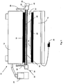
- a press brake 10 shown in FIG. 1 has an upper tool 12 that can be driven vertically downward against a lower tool 14 for working movement to bend a workpiece 16 resting on the lower tool 14.
- the upper tool 12 and the lower tool 14 have tool edges 18 and 20, which have a corresponding shape, in order to bend the workpiece 16 into a specific shape.
- an opening gap 22 between the upper tool 12 and the workpiece 16 is gradually closed.
- the press brake 10 is controlled by a controller 24 and may be activated by a footswitch 26, for example.
- the support arms 28 carry a light transmitter 30 and a spatially resolving receiver 32, which are parts of an opto-electronic safety device 33.
- the light transmitter 30 has a light source 36, for example a laser diode and a transmitting optics 38, which expands the transmitted light into a parallel light beam 34.
- the receiver 32 has a camera-like construction and has a spatially resolving two-dimensional light receiver 40, for example a CMOS matrix receiver, which is acted on by the light beam 34.
- a receiving optics 42 the light is imaged onto the light receiver 40.
- An optical filter 44 whose passband is tuned to the wavelength of the light emitter 36 can filter ambient light, thus improving the signal-to-noise ratio.
- the parallel expanded light beam 34 passes through the opening gap 22 along the lower edge 18 of the upper tool 12.
- the light beam 34 is a volume-shaped protection region 46 defined with marginal rays 62 and 64.
- an evaluation device 48 is provided, which, e.g. could be arranged on the receiver 32 or in the machine control 24. If there is an at least partial interruption of the light beam 34 within the protection area 46, as might be caused for example by an object 50 that could be a finger, this is recognized by the image on the spatial resolution light receiver 40 ( Figure 2).
- the evaluation device 48 conditions can be checked whether the object is e.g. a valid one or not. If a danger is finally detected in the evaluation device 48 as a result of the penetration of the object 50 into the protective area 46, a switching signal is triggered, for example for stopping the upper tool 12. This protects an operator from injury from the upper tool 12.
- the transmitter 30 and the receiver 32 are arranged such that a part of the tool edge 18 projects into the light beam 34.
- this image is recognized as permissible in the evaluation unit 48. This can e.g. be realized by storing a reference image or the like.
- the light beam 34 is widened such that it substantially fully illuminates the receiving optics of the receiver 32. So that the light receiver 40 is always hit even with vibrations, the cross section of the light beam 34 at the location of the light receiver 32 is smaller than the light receiver 40.
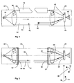
- the adjustment beam 58 that has entered the receiving optics is partially reflected at an optical interface 68.
- the reflected part 69 strikes a target disk 70 arranged in the second adjustment plate 54, which is designed as a ground glass.
- a target target 76 is marked on the ground glass 70, so that by rotating the receiver 32 in the directions of arrows 72 and 74 about two mutually perpendicular axes V and H, the receiver 32 is aligned so that the reflected portion 69 of the alignment beam 58 hits the target , Then the receiver is at least roughly aligned.
- the impact point 78 of the Justagelichtstrahls 58 is detected on the spatially resolving light receiver 40 and a deviation dx or dy determined by a target impact point 80.
- FIG. 7 shows a view of the detector surface 84 of the spatially resolving light receiver 40.
- the target impact point 80 is represented by a cross.
- the deviations dx and dy are represented by means of an electronic display 82.
- the display 82 is formed as a seven-segment display.
- the receiver 32 by further defined rotation in directions 72 and 74 are aligned until the impact point 78 is at the target impact point 80.
- Fig. 5 shows the first adjustment aperture 54 in plan view.
- the Justageblende 54 still two slot openings 86 and 88, passes through the light of the light beam 34, to form two auxiliary Justagelichtstrahlen. These are used for the coarse alignment as well as described above with respect to the adjustment beam 58.
- the auxiliary Justagestrahlen simplify the adjustment, since they are due to their larger cross-section due to the slot openings 86 and 88 at the beginning of the adjustment, when the safety device is still unadjusted to find better.
- the second Justageblende 54 also has two second slot openings 90 and 92, in which case, however, the longitudinal directions of the slot openings 90 and 92 are perpendicular to the longitudinal directions of the first slot openings 86 and 88. With approximately correct alignment of transmitter 30 and receiver 32 then only an approximately rectangular Operaquerschnit the auxiliary Justageestrahlen is transmitted.
- This part of the auxiliary adjustment jets also transmitted by the second adjustment aperture 54 has a special significance for the fine adjustment by means of the light receiver 40, as will be explained with reference to FIG. 7.
- the reference numerals 94 and 96 show the impact point of the auxiliary alignment light beams.
- a rotation of the receiver dr with respect to the Justagestrahlen can be determined with the auxiliary Justageestrahlen and a corresponding correction possible.
- the auxiliary adjustment beams also serve to facilitate locating the points of impingement, which are detected in the adjustment process only as adjustment light beams when they lie in a specific search region 98 of the detector surface 84.
- the corresponding impact points 78, 94 and 96 are measured by the light receiver 40 and the deviations dx, dy and the rotation dr are output on the display 82.
- the display 82 is designed as a seven-segment display, indicating the deviations or rather the directions of the deviations are very simple and visual representable and that according to the specifications of the following table No impact points detected Invalid pattern, too many points All impact points to the left of the target points All impact points above the target points All impact points left above the target points All impact points to the right of the target points _ All impact points below the target points All impact points right below the target points Impact points of the central Justierstrahls in the target but auxiliary Justageestrahlen left-twisted Impact points of the central Justierstrahls in the target but right-turned auxiliary Justageestrahlen Distance between the points of impact of the auxiliary alignment jets outside the tolerance (error) All impact points in the target points
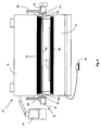
- two third adjustment apertures 100 are provided, with the aid of which the safety device 33 can be aligned such that the light beam 34 runs exactly parallel to the tool edge 18.
- the two third adjustment apertures 100 are of identical design and, like the first justegraph end 52, have an aperture 156 for the central adjustment light beam and two slit apertures 186 and 188 for the auxiliary alignment light beams.
- the adjustment apertures 100 are mounted at the ends of the tool edge 18 in a predetermined manner, e.g. magnetically attached. 8 shows the press brake 10 with the safety system 33 according to the invention with mounted first, second and third adjustment apertures 52, 54 and 100.
- the light beam 34 is aligned exactly parallel to the edge of the tool. Thereafter, the receiver 32 can be accurately aligned, as described above.
Abstract
Description
Die Erfindung betrifft ein Verfahren zur Justage einer optoelektronischen Sicherheitseinrichtung einer gefahrbringenden Maschine, wie Biegepresse oder dergleichen sowie eine optoelektronische Sicherheitseinrichtung.The invention relates to a method for adjusting an optoelectronic safety device of a dangerous machine, such as a bending press or the like, as well as an optoelectronic safety device.
Die Erfindung ist nicht auf Biegepressen im engeren Sinne begrenzt und kann ebenso bei Abkantpressen, Stanzmaschinen, Schneidemaschinen und anderen Maschinen verwendet werden, bei denen Maschinenteile gefahrbringende Arbeitsbewegungen gegeneinander ausführen. Bei einer Biegepresse erfolgt die Umformung des Werkstücks im Wesentlichen dadurch, dass das Werkstück mit einem Biegestempel gegen eine Matrize gepresst wird. Die gewünschte Formgebung lässt sich durch entsprechende Ausbildung des Biegestempels und der Matrize erreichen. Häufig ist der Biegestempel ein Werkzeug, das an einem ersten, beweglichen Maschinenteil angeordnet ist, während die Matrize an einem zweiten, feststehenden Maschinenteil sitzt. Da es jedoch nur auf die Relativbewegung der beiden Maschinenteile zueinander ankommt, kann alternativ auch die Matrize bewegt sein oder es können beide Maschinenteile gegeneinander bewegt werden. Die erfindungsgemäße Sicherheitseinrichtung und das erfindungsgemäße Verfahren zur Justierung der Sicherheitseinrichtung kann in allen genannten Fällen zur Anwendung kommen.The invention is not limited to bending presses in the strict sense and can also be used in press brakes, punching machines, cutting machines and other machines in which machine parts perform dangerous working movements against each other. In a bending press, the forming of the workpiece is essentially carried out by pressing the workpiece against a die with a bending punch. The desired shape can be achieved by appropriate design of the punch and the die. Frequently, the punch is a tool which is arranged on a first, movable machine part, while the die is seated on a second, stationary machine part. However, since it depends only on the relative movement of the two machine parts to each other, alternatively, the die can be moved or both machine parts can be moved against each other. The safety device according to the invention and the method according to the invention for adjusting the safety device can be used in all cases mentioned.
Da von einer Biegepresse eine erhebliche Gefahr für das Bedienpersonal ausgeht, insbesondere die Gefahr von Quetschungen oder Abtrennung von Körperteilen, ist es bekannt, optoelektronische Sicherheitseinrichtungen vorzusehen, wie dies beispielsweise aus der WO 03/104711 bekannt ist. Bei dieser Einrichtung sind an dem sich bewegenden Maschinenteil ein Lichtsender und ein kameraartiger Lichtempfänger fest angeordnet, so dass ein von dem ausgedehnten Strahl parallelen Lichts definierte Schutzfeld auf einen Eingriff hin überwacht werden kann. Das Schutzfeld erstreckt sich entlang der Werkzeugkante des sich bewegenden Werkzeugteils.Since a considerable danger for the operator originates from a bending press, in particular the risk of bruising or separation of body parts, it is known to provide opto-electronic safety devices, as is known, for example, from WO 03/104711. In this device, a light emitter and a camera-like light receiver are fixedly arranged on the moving machine part, so that a protective field defined by the extended beam parallel light can be monitored for engagement. The protective field extends along the tool edge of the moving tool part.
Beim Einsatz dieser Sicherheitseinrichtung muss zur sicheren Funktion bei der Montage eine exakte Justage berücksichtigt werden. Die erforderliche exakte Justage ist unter anderem darin begründet, dass das Empfangselement zweidimensional ausgebildet ist, beispielsweise aus mehreren einzelnen Photoelementen matrixförmig zusammengefügt ist. Eine fehlerhafte Justage hätte nämlich zur Folge, dass die Informationen, die in der Lichtverteilung des Lichtbündelquerschnittes liegen, nicht vollständig oder falsch ausgewertet werden. Die erforderliche Sicherheit wäre nicht gewährleistet.When using this safety device, an exact adjustment must be taken into account for safe function during assembly. The required exact adjustment is due, inter alia, to the fact that the receiving element is formed two-dimensionally, for example, is assembled in matrix form from a plurality of individual photoelements. A faulty adjustment would have the consequence that the information that is in the light distribution of the light beam cross-section, not fully or incorrectly evaluated. The required security would not be guaranteed.
Zur Justage ist deshalb nach der WO 03/104711 vorgesehen, dass auf dem Sender und dem Empfänger eine Maske gesetzt werden kann, mit der ein Muster, beispielsweise ein Kreuz, vom Sender erzeugt und bei korrekter Justage durch die Empfängermaske hindurch auf den Empfänger gelangt. Nachteilig bei diesem bekannten Verfahren zur Justage ist, dass damit nur eine relativ grobe Ausrichtung erreicht werden kann, so dass auch die Detektionssicherheit der Sicherheitseinrichtung entsprechend begrenzt ist.For adjustment is therefore provided according to WO 03/104711 that on the transmitter and the receiver, a mask can be set, with a pattern, such as a cross, generated by the transmitter and passes through the receiver mask through the receiver with correct adjustment. A disadvantage of this known method for adjustment that only a relatively coarse alignment can be achieved so that the detection reliability of the safety device is limited accordingly.
Ausgehend von diesem Stand der Technik liegt der Erfindung die Aufgabe zugrunde, ein verbessertes Verfahren zur Justage einer Sicherheitseinrichtung bereitzustellen, wodurch eine exaktere Ausrichtung des Empfängers auf den Lichtsender erreicht werden kann sowie eine entsprechende Sicherheitseinrichtung bereitzustellen.Based on this prior art, the present invention seeks to provide an improved method for adjusting a safety device, whereby a more accurate alignment of the receiver can be achieved on the light emitter and to provide a corresponding safety device.
Zur Lösung dieser Aufgabe sieht die Erfindung ein Verfahren mit den Merkmalen des Anspruchs 1 vor sowie eine Sicherheitseinrichtung mit den Merkmalen des Anspruchs 10.To achieve this object, the invention provides a method with the features of claim 1 and a safety device with the features of
Der wesentliche Vorteil des erfindungsgemäßen Verfahrens besteht darin, dass durch die Kombination von optischer Vorjustage und danach weiterer Feinjustage mittels Auswertung der Signale des Lichtempfängers eine erheblich verbesserte Justierung erreicht werden kann. Dies ist überraschend, da bisher die Meinung herrschte, dass eine optische Justage schon eine ausreichende Ausrichtung bewirke. Dabei wird für die Vor- und Feinjustage dieselbe Konfiguration benutzt, d.h. es werden dieselben Justageblenden verwendet, so dass die komplette Justage in einem Stück durchgeführt werden kann.The essential advantage of the method according to the invention is that a significantly improved adjustment can be achieved by the combination of optical pre-adjustment and then further fine adjustment by evaluation of the signals of the light receiver. This is surprising, because so far the opinion prevailed that an optical adjustment already causes a sufficient alignment. In this case, the same configuration is used for the pre- and fine adjustment, i. The same adjustment covers are used so that the complete adjustment can be carried out in one piece.
Insgesamt wird so eine optimal justierte Sicherheitseinrichtung erhalten, wodurch nicht nur die Sicherheit aufgrund der Vermeidung einer Fehljustage erhöht ist, sondern auch eine optimale Funktion hinsichtlich der Objekterkennung über den Lichtstrahlquerschnitt und damit über den Schutzfeldquerschnitt gewährleistet ist. Durch eine Verbesserung der Objekterkennung besteht die Möglichkeit, dass die Einrichtung auch noch weitere Nicht-Sicherheitszwecke, wie beispielsweise die Vermessung von Objekten innerhalb des Schutzfeldes, erfüllen kann.Overall, such an optimally adjusted safety device is obtained, whereby not only the safety is increased due to the avoidance of misalignment, but also an optimal function with respect to the object recognition over the light beam cross section and thus over the protective field cross section is ensured. By improving the object recognition, there is the possibility that the device can also fulfill other non-safety purposes, such as the measurement of objects within the protective field.
Je kleiner der Strahlquerschnitt des Justagelichtstrahls ist, desto genauer kann die Justage sein, so dass der Justagelichtstrahl vorteilhafterweise einen möglichst kleinen Strahlquerschnitt aufweist, aber dennoch auf der Zielscheibe sichtbar ist. Dabei ist es vorteilhaft und erhöht die Genauigkeit der Justage weiterhin, wenn der vom Lichtsender erzeugt parallele Lichtstrahl, der den Schutzbereich definiert, einen großen Strahlquerschnitt hat, damit eine große Zielscheibe mit einem großem Fangbereich einsetzbar ist.The smaller the beam cross section of the Justagelichtstrahls, the more accurate the adjustment may be, so that the Justagelichtstrahl advantageously has the smallest possible beam cross-section, but is still visible on the target. It is advantageous and further increases the accuracy of the adjustment, when the light beam generated by the light emitter parallel, which defines the scope, has a large beam cross-section, so that a large target with a large catch area can be used.
Wenn der Justagelichtstrahl nach Durchtritt durch die zweite Justageblende an einer optischen Grenzfläche in der Empfangsoptik teilreflektiert wird, muss keine gesonderte Spiegelfläche vorgesehen sein.If the Justagelichtstrahl is partially reflected after passing through the second Justagebrende at an optical interface in the receiving optics, no separate mirror surface must be provided.
Die Feinjustage erfolgt vorteilhafterweise mittels einer elektronischen Anzeige, die die Abweichung des Auftreffpunktes des nicht reflektierten Teils des Justagestrahls auf dem Lichtempfänger vom Soll-Auftreffpunkt anzeigt.The fine adjustment is advantageously carried out by means of an electronic display, which indicates the deviation of the impact point of the non-reflected part of the Justagestrahls on the light receiver from the target impact point.
Eine sehr einfach gestaltete und kostengünstige, aber dennoch aussagekräftige Anzeige ist durch eine Sieben-Segment-Anzeige gegeben, die allerdings nur die Richtung der Abweichung mittels Symbolik anzeigen kann. Das reicht aber für eine Justage aus.A very simple and cost-effective, but nevertheless meaningful display is given by a seven-segment display, which, however, can only indicate the direction of the deviation by means of symbolism. But that's enough for an adjustment.
Zusätzlich zur Ausrichtung von Lichtsender und Lichtempfänger ist in Weiterbildung der Erfindung vorgesehen, dass der Justagelichtstrahl auch parallel zu einer die Gefahr bringenden Werkzeugkante ausgerichtet wird.In addition to the alignment of light emitter and light receiver is provided in a further development of the invention that the Justagelichtstrahl is also aligned parallel to a dangerous edge of the tool.
Dies geschieht vorteilhafterweise durch dritte Justageblenden, die an beiden Seiten der Werkzeugkante ausgerichtet angesetzt werden. Der Justagelichtstrahl und damit der Lichtsender wird dann derart ausgerichtet, dass er Öffnungen beider dritten Justageblenden durchsetzt.This is advantageously done by third Justageblenden, which are recognized aligned on both sides of the tool edge. The Justagelichtstrahl and thus the light emitter is then aligned so that it passes through openings of both third Justageblenden.
Mit Vorteil werden zwei zusätzliche Hilfs-Justagelichtstrahlen parallel zum ersten erzeugt, damit die Justage vereinfacht und schneller durchführbar wird. Durch die Verwendung der zwei zusätzlichen Hilfs-Justagelichtstrahlen lässt sich der eigentliche Justierstrahl besser auffinden und in den jeweiligen Phasen des Justierprozesses eine Vorjustierung durchführen.Advantageously, two additional auxiliary Justagelichtstrahlen are generated parallel to the first, so that the adjustment is simplified and faster. By using the two additional auxiliary Justagelichtstrahlen the actual Justierstrahl can find better and perform a pre-adjustment in the respective phases of the adjustment process.
Vorzugsweise ist die Zielscheibe auf der zweiten Justageplatte als Mattscheibe ausgebildet. Durch die Kombination von Justageblende und Zielscheibe kann eine Komponente eingespart werden. Eine Mattscheibe hat den Vorteil, dass der den Justagezustand anzeigende Lichtspot in seiner Intensität wenig gedämpft wird und dadurch mit gutem Kontrast sichtbar ist.Preferably, the target is formed on the second adjustment plate as a ground glass. The combination of adjustment diaphragm and target can save a component. A ground glass has the advantage that the light spot indicating the adjustment state is little attenuated in its intensity and is therefore visible with good contrast.
Die Erfindung wird im Folgenden anhand eines Ausführungsbeispiels unter Bezugnahme auf die Zeichnung im Einzelnen erläutert. In der Zeichnung zeigen:
- Fig. 1
- eine schematische Frontansicht einer Biegepresse mit einer erfindungsgemäßen Sicherheitseinrichtung;
- Fig. 2
- eine schematische Darstellung der Sicherheitseinrichtung im Schnitt entlang deren optischer Achse;
- Fig. 3
- eine Ansicht wie Fig. 2 mit erster und zweiter Justageblende;
- Fig. 4, 5 und 6
- erste, zweite und dritte Justageblenden;
- Fig. 7
- eine schematische Ansicht eines Lichtempfängers der erfindungsgemäßen Sicherheitseinrichtung.
- Fig. 8
- eine Gesamtansicht wie Fig. 1 mit Justageblenden an der Sicherheitseinrichtung;
- Fig. 1
- a schematic front view of a bending press with a safety device according to the invention;
- Fig. 2
- a schematic representation of the safety device in section along its optical axis;
- Fig. 3
- a view like Figure 2 with first and second adjustment aperture.
- 4, 5 and 6
- first, second and third adjustment apertures;
- Fig. 7
- a schematic view of a light receiver of the safety device according to the invention.
- Fig. 8
- an overall view as shown in Figure 1 with Justageblenden on the safety device.
Eine in Fig. 1 gezeigte Gesenkbiegepresse 10 besitzt ein Oberwerkzeug 12, das zu einer Arbeitsbewegung vertikal nach unten gegen ein Unterwerkzeug 14 angetrieben werden kann, um ein auf dem Unterwerkzeug 14 aufliegendes Werkstück 16 zu biegen. Das Oberwerkzeug 12 und das Unterwerkzeug 14 besitzen Werkzeugkanten 18 und 20, die eine entsprechende Form aufweisen, um das Werkstück 16 in eine bestimmte Form zu biegen. Während der Arbeitsbewegung wird ein Öffnungsspalt 22 zwischen dem Oberwerkzeug 12 und dem Werkstück 16 allmählich geschlossen. Die Gesenkbiegepresse 10 wird gesteuert von einer Steuerung 24 und kann beispielsweise durch einen Fußschalter 26 aktiviert werden.A
An beiden Seiten des Oberwerkzeugs 12 ist jeweils ein Haltearm 28 vorgesehen. Die Haltearme 28 tragen einen Lichtsender 30 und einen ortsauflösenden Empfänger 32, die Teile einer optoelektronischen Sicherheitseinrichtung 33 sind. Der Lichtsender 30 besitzt eine Lichtquelle 36, beispielsweise eine Laserdiode und eine Sendeoptik 38, die das Sendelicht zu einem parallelen Lichtstrahl 34 aufweitet. Der Empfänger 32 ist kameraartig aufgebaut und besitzt einen ortsauflösenden zweidimensionalen Lichtempfänger 40, beispielsweise einen CMOS-Matrix-Empfänger, der von dem Lichtstrahl 34 beaufschlagt wird. Über eine Empfangsoptik 42 wird das Licht auf den Lichtempfänger 40 abgebildet. Ein optisches Filter 44, dessen Durchlassbereich auf die Wellenlänge des Lichtsenders 36 abgestimmt ist, kann Umgebungslicht filtern und verbessert somit das Signal/Rausch-Verhältnis.On both sides of the
Der parallel aufgeweitete Lichtstrahl 34 durchquert den Öffnungsspalt 22 entlang der Unterkante 18 des Oberwerkzeugs 12. Durch den Lichtstrahl 34 ist ein volumenförmiger Schutzbereich 46 definiert mit Randstrahlen 62 und 64. Durch den Lichtempfänger 40 kann erkannt werden, ob der Lichtstrahl 34 ganz oder teilweise unterbrochen ist (Fig. 2). Dazu ist eine Auswerteeinrichtung 48 vorgesehen, die z.B. an dem Empfänger 32 oder auch in der Maschinensteuerung 24 angeordnet sein könnte. Wenn eine zumindest teilweise Unterbrechung des Lichtstrahls 34 innerhalb des Schutzbereichs 46 vorliegt, wie dies beispielsweise durch ein Objekt 50, das ein Finger sein könnte, verursacht sein könnte, wird dies durch die Abbildung auf den ortsauflösenden Lichtempfänger 40 erkannt (Fig. 2). In der Auswerteeinrichtung 48 können Bedingungen abgeprüft werden, ob das Objekt z.B. ein zulässiges ist oder nicht. Wenn in der Auswerteeinrichtung 48 schließlich eine Gefahr durch das Eindringen des Objektes 50 in den Schutzbereich 46 erkannt wird, wird ein Schaltsignal ausgelöst, beispielsweise zum Anhalten des Oberwerkzeugs 12. Dadurch wird eine Bedienperson vor Verletzungen durch das Oberwerkzeug 12 geschützt.The parallel expanded
Damit der Schutzbereich 46 direkt an der Werkzeugkante 18 anschließt, sind der Sender 30 und der Empfänger 32 derart angeordnet, dass ein Teil der Werkzeugkante 18 in den Lichtstrahl 34 hineinragt. Zwar wird dann die Werkzeugkante 18 auf den ortsauflösenden Lichtempfänger 40 abgebildet, aber diese Abbildung wird in der Auswerteeinheit 48 als zulässig erkannt. Dies kann z.B. durch Speicherung eines Referenzbildes oder ähnlichem realisiert sein.So that the
Wie aus Fig. 2 zu erkennen ist, ist der Lichtstrahl 34 derart aufgeweitet, dass er die Empfangsoptik des Empfängers 32 im Wesentlichen voll ausleuchtet. Damit auch bei Vibrationen der Lichtempfänger 40 stets getroffen wird, ist der Querschnitt des Lichtstrahls 34 am Ort des Lichtempfängers 32 kleiner als der Lichtempfänger 40.As can be seen from FIG. 2, the
Anhand der Fig. 3 werden im Folgenden die wesentlichen Prinzipien des Justageverfahrens erläutert.With reference to FIG. 3, the essential principles of the adjustment method are explained below.
In einem ersten Schritt werden Sender 30 und Empfänger 32 zueinander ausgerichtet. Dazu wird eine erste Justageblende 52 vor den Sender 30 montiert und eine zweite Justageblende 54 vor den Empfänger 32. Die Montage erfolgt dabei reproduzierbar derart, dass die Justageblenden 52 und 54 exakt in einer gewünschten Weise zu Sender 30 bzw. Empfänger 32 ausgerichtet sind. Die erste Justageblende 52 weist eine kleine Öffnung 56 auf, durch die ein Teil des Lichtstrahls 34 durchgelassen wird und somit einen Justagelichtstrahl 58 mit kleinem Querschnitt bildet, der parallel zur optischen Achse 60 verläuft. Der größte Teil des Lichtstrahls 34 ist ausgeblendet, wie dies durch gestrichelte Darstellung der ansonsten vorhandenen Randstrahlen 62 und 64 angedeutet ist.In a first step,
Der Sender 30 wird nun so ausgerichtet, dass der Justagestrahl 58 eine Öffnung 66 der zweiten Justageplatte 54 trifft und in die Empfangsoptik 42 des Empfängers 32 eintritt. Damit ist der Sender 30 auf den Empfänger 32 ausgerichtet.The
Zur Ausrichtung des Empfängers 32 auf den Sender 30 wird der in die Empfangsoptik eingetretene Justagestrahl 58 an einer optischen Grenzfläche 68 teilreflektiert. Der reflektierte Teil 69 trifft auf eine in der zweiten Justageplatte 54 angeordnete Zielscheibe 70, die als Mattscheibe ausgebildet ist. Auf der Mattscheibe 70 ist ein Soll-Ziel 76 markiert, so dass durch Drehen des Empfängers 32 in Pfeilrichtungen 72 und 74 um zwei zueinander senkrechte Achsen V und H der Empfänger 32 so ausgerichtet wird, dass der reflektierte Teil 69 des Justagestrahls 58 das Ziel trifft. Dann ist der Empfänger zumindest grob nach Augenmaß ausgerichtet.For aligning the
Danach wird in einem weiteren Schritt der Auftreffpunkt 78 des Justagelichtstrahls 58 auf dem ortsauflösenden Lichtempfänger 40 festgestellt und eine Abweichung dx bzw. dy von einem Soll-Auftreffpunkt 80 ermittelt. Dies ist schematisch auch in Fig. 7 dargestellt, die eine Ansicht der Detektorfläche 84 des ortsauflösenden Lichtempfängers 40 zeigt. Der Soll-Auftreffpunkt 80 ist mittels eines Kreuzes dargestellt. Die Abweichungen dx und dy werden mittels einer elektronischen Anzeige 82 dargestellt. Wie weiter unten erläutert, ist die Anzeige 82 als Sieben-Segment-Anzeige ausgebildet. Nun kann der Empfänger 32 durch weiteres definiertes Drehen in Richtungen 72 und 74 exakt ausgerichtet werden, bis der Auftreffpunkt 78 auf dem Soll-Auftreffpunkt 80 liegt.Thereafter, in a further step, the
In Weiterbildung der Erfindung sind noch weitere Justageschritte vorgesehen, die zusätzlich zu den bereits erläuterten vorgesehen sind und im Folgenden anhand der Fig. 4 bis 7 erläutert werden.In a further development of the invention, further adjustment steps are provided, which are provided in addition to those already explained and are explained below with reference to FIGS. 4 to 7.
Fig. 5 zeigt die erste Justageblende 54 in Draufsicht. Jeweils neben der Öffnung 56 weist die Justageblende 54 noch zwei Schlitzöffnungen 86 und 88 auf, durch die Licht des Lichtstrahls 34 tritt, zur Bildung von zwei Hilfs-Justagelichtstrahlen. Diese werden für die Grobausrichtung nach Augenmaß genauso eingesetzt, wie oben in Bezug auf den Justagestrahl 58 beschrieben. Die Hilfs-Justagestrahlen vereinfachen dabei die Justage, da sie wegen ihres größeren Querschnitts aufgrund der Schlitzöffnungen 86 und 88 zu Beginnn der Justage, wenn die Sicherheitseinrichtung noch unjustiert ist, besser zu finden sind. Dabei weist die zweite Justageblende 54 ebenfalls zwei zweite Schlitzöffnungen 90 und 92 auf, wobei hier jedoch die Längsrichtungen der Schlitzöffungen 90 und 92 senkrecht zu den Längsrichtungen der ersten Schlitzöffnungen 86 und 88 liegen. Bei in etwa korrekter Ausrichtung von Sender 30 und Empfänger 32 wird dann nur ein in etwa rechteckiger Teilquerschnit der Hilfs-Justagestrahlen durchgelassen.Fig. 5 shows the
Dieser auch von der zweiten Justageblende 54 durchgelassene Teil der Hilfs-Justagestrahlen hat eine besondere Bedeutung für die Feinjustage mittels des Lichtempfängers 40, wie anhand der Fig. 7 erläutert wird. Bei den Bezugsziffern 94 und 96 ist der Auftreffpunkt der Hilfs-Justagelichtstrahlen dargestellt. Wie bereits aus der Darstellung hervorgeht, ist mit den Hilfs-Justagestrahlen auch eine Verdrehung dr des Empfängers gegenüber den Justagestrahlen feststellbar und eine entsprechende Korrektur möglich. Ausserdem dienen die Hilfs-Justagestrahlen auch einem leichteren Auffinden der Auftreffpunkte, die im Justageprozess nur als Justagelichtstrahlen erkannt werden, wenn sie in einem bestimmten Suchbereich 98 der Detektorfläche 84 liegen.This part of the auxiliary adjustment jets also transmitted by the
Die entsprechenden Auftreffpunkte 78, 94 und 96 werden von dem Lichtempfänger 40 gemessen und die Abweichungen dx, dy und die Verdrehung dr an der Anzeige 82 ausgegeben. Die Anzeige 82 ist als Sieben-Segment-Anzeige ausgebildet, womit die Abweichungen oder besser gesagt die Richtungen der Abweichungen sehr einfach und bildlich darstellbar sind und zwar nach den Vorgaben der nachfolgenden Tabelle
![]()
![]()
![]()
![]()
![]()
![]()
![]()
![]()
![]()
![]()
![]()
![]()
![]()
![]()
![]()
![]()
![]()
![]()
![]()
![]()
![]()
![]()
![]()
![]()
Des Weiteren sind zwei dritte Justageblenden 100 vorgesehen, mit Hilfe derer die Sicherheitseinrichtung 33 derart ausgerichtet werden kann, dass der Lichtstrahl 34 exakt parallel zur Werkzeugkante 18 verläuft. Die beiden dritten Justageblenden 100 sind identisch ausgebildet und weisen wie die erste Justegablende 52 eine Öffnung 156 für den zentralen Justagelichtstrahl und zwei Schlitzöffnungen 186 und 188 für die Hilfs-Justagelichtstrahlen auf. Die Justageblenden 100 werden an den Enden der Werkzeugkante 18 in fest vorgegebener Weise montiert, z.B. magnetisch befestigt. Die Fig. 8 zeigt die Gesenkbiegepresse 10 mit dem erfindungsgemäßen Sicherheitssystem 33 mit montierten ersten, zweiten und dritten Justageblenden 52, 54 und 100. Wenn der Justagestrahl 58 und die Hilfs-Justagestrahlen die entsprechenden Öffnungen 56, 86, 88 bzw, 156, 186, 188 der ersten und dritten Justageblenden 52 und 100 treffen, ist der Lichtstrahl 34 exakt parallel zur Werkzeugkante ausgerichtet. Danach kann der Empfänger 32 exakt ausgerichtet werden, wie oben beschrieben.Furthermore, two
Claims (15)
- Method for the alignment of an optoelectronic safety device (33) in a hazardous machine, such as a bending press (10) or the like, having the following method steps:- producing at least one alignment light beam (58) parallel to but outside the optical axis (60) by positioning a first alignment diaphragm (52) in front of a light transmitter (30),- positioning a second alignment diaphragm (54) in front of a receiver (32),- orienting the light transmitter (30) such that the alignment light beam (58) passes through an opening (66) in the second alignment diaphragm (54),- orienting the receiver (32) such that the alignment light beam (58) strikes a desired impingement point (80),characterized in that- the alignment light beam (58) which passed through the opening (66) in the second alignment diaphragm (54) is partially reflected and- the receiver (32) is initially oriented by eye by virtue of an impingement point of the reflected portion (69) of the alignment light beam (58) visibly striking a target screen (70) and being oriented towards a desired target (76) and- in that, thereafter, the impingement point (78) of the non-reflected portion of the alignment beam (58) on the receiver (40) is determined electronically and is compared to a desired impingement point (80) on the receiver (40) in an evaluation unit (48).
- Method according to Claim 1, characterized in that the alignment light beam (58) has as small a beam cross section as possible, but is still visible on the target screen (70).
- Method according to Claim 1 or 2, characterized in that the alignment light beam (58) is partially reflected on an optical interface (68) in a receiving optical system (42).
- Method according to one of the preceding claims, characterized in that the deviation (dx, dy) of the impingement point (78) of the non-reflected portion of the alignment beam (58) on the light receiver (40) from the desired impingement point (80) is displayed on an electronic display (82).
- Method according to Claim 4, characterized in that only the direction of the deviation is displayed using symbols.
- Method according to one of the preceding claims, characterized in that the alignment light beam (58) is oriented parallel to a hazardous die edge (18).
- Method according to Claim 6, characterized in that third alignment diaphragms (100) are mounted in a manner such that they are oriented on both ends of the die edge (18) and the alignment light beam (58) is oriented such that it passes through openings (156) in both third alignment diaphragms (100).
- Method according to one of the preceding claims, characterized in that two additional auxiliary alignment light beams are produced parallel to the first one.
- Method according to one of the preceding claims, characterized in that transmitter (30) and receiver (32) are pre-aligned in the respective phases of the alignment process with the aid of the two additional auxiliary alignment light beams.
- Optoelectronic safety device for a machine, in particular a bending press (10), having a light transmitter (30) with a transmitting optical system (38) for illuminating a protection zone (46) using parallel light, a two-dimensional light receiver (40) with a receiving optical system (42, 44) for receiving the transmitted light, and having an evaluation and control device (48) for producing a switching signal, for example for stopping a first die part (12) if an intrusion into the protection zone (46) was recognized by the light receiver (40), and wherein the protection zone (46) runs parallel to a die edge (18) of the first die (12), for which reason the light transmitter (30) and the light receiver (40) are installed at the ends of the first die (12), having a first alignment diaphragm (52) for fitting on the light transmitter (30) for producing an alignment light beam (58) and having a second alignment diaphragm (54) for fitting on the light receiver (32) for allowing through the alignment light beam (58) into the receiving optical system (42, 44), characterized in that an optical interface (68) is provided in the receiving optical system (42, 44) for the partial reflection of the alignment beam (58) and a target screen (70) is arranged on the second alignment diaphragm (54) for the optical display of the reflected portion (69) of the alignment beam (58) for the pre-alignment, and in that the evaluation unit has means for recognizing and outputting a deviation (dx, dy) of an impingement point (78) of the non-reflected portion of the alignment light beam (58) from a desired impingement point (80).
- Safety device according to Claim 10, characterized in that the target screen is a ground glass screen (70).
- Safety device according to one of the preceding Claims 10 to 11, characterized in that two further auxiliary alignment light beams can be produced by means of the first alignment diaphragm (52).
- Safety device according to one of the preceding Claims 10 to 12, characterized in that two third alignment diaphragms (100) of identical design are provided for the orientation of the light beam parallel to the die edge (18).
- Safety device according to one of the preceding Claims 10 to 13, characterized in that an electronic display (82) is provided for the display of the direction of the deviation of the impingement point (78) of the alignment beam (58) from the desired impingement point (80).
- Safety device according to Claim 14, characterized in that the display (82) is a seven segment display.
Applications Claiming Priority (2)
| Application Number | Priority Date | Filing Date | Title |
|---|---|---|---|
| DE102004017285A DE102004017285A1 (en) | 2004-04-08 | 2004-04-08 | Method for adjusting a safety device and optoelectronic safety device |
| DE102004017285 | 2004-04-08 |
Publications (2)
| Publication Number | Publication Date |
|---|---|
| EP1589355A1 EP1589355A1 (en) | 2005-10-26 |
| EP1589355B1 true EP1589355B1 (en) | 2007-03-28 |
Family
ID=34933790
Family Applications (1)
| Application Number | Title | Priority Date | Filing Date |
|---|---|---|---|
| EP05003350A Not-in-force EP1589355B1 (en) | 2004-04-08 | 2005-02-17 | Method to adjust a security system and an optoelectronic security system |
Country Status (3)
| Country | Link |
|---|---|
| EP (1) | EP1589355B1 (en) |
| AT (1) | ATE358283T1 (en) |
| DE (2) | DE102004017285A1 (en) |
Families Citing this family (4)
| Publication number | Priority date | Publication date | Assignee | Title |
|---|---|---|---|---|
| DE102006056648A1 (en) | 2006-11-29 | 2008-06-05 | Sick Ag | Opto-electronic sensor |
| DE102007006306A1 (en) * | 2007-01-30 | 2008-07-31 | Pilz Gmbh & Co. Kg | Safety device for e.g. die bending press machine, has light emitter producing light rays, with light source having predominantly incoherent radiation, and light receiver with image optics having focus and aperture arranged in focus |
| DE102013205456B4 (en) * | 2013-03-27 | 2021-05-06 | Carl Zeiss Industrielle Messtechnik Gmbh | Alignment element for an optical distance sensor, optical sensor arrangement and method for aligning an optical distance sensor |
| EP2939758B1 (en) * | 2014-04-29 | 2019-01-16 | Schechtl Maschinenbau GmbH | Forming device for plastically forming a component comprising a safety device |
Family Cites Families (7)
| Publication number | Priority date | Publication date | Assignee | Title |
|---|---|---|---|---|
| AUPN744696A0 (en) * | 1996-01-05 | 1996-02-01 | Appleyard, Thomas John | Safety apparatus and protection method for machines |
| DE19717299C2 (en) * | 1996-08-20 | 2002-03-14 | Fiessler Elektronik Ohg | Protection device for machines, in particular for press brakes, cutting machines or punching machines |
| DE10106755B4 (en) * | 2001-02-14 | 2006-05-24 | Leuze Electronic Gmbh & Co Kg | Optoelectronic device |
| DE10114784A1 (en) * | 2001-03-26 | 2002-10-10 | Sick Ag | Device for monitoring a protective field |
| DE10138223A1 (en) * | 2001-08-03 | 2003-02-20 | Sick Ag | Method of controlling a light grid |
| JP4511345B2 (en) * | 2002-06-11 | 2010-07-28 | デイビス,ケヴィン,ステファン | Safety system |
| DE20317622U1 (en) * | 2003-11-14 | 2004-02-12 | Sick Ag | Photoelectric barrier |
-
2004
- 2004-04-08 DE DE102004017285A patent/DE102004017285A1/en not_active Withdrawn
-
2005
- 2005-02-17 DE DE502005000511T patent/DE502005000511D1/en active Active
- 2005-02-17 EP EP05003350A patent/EP1589355B1/en not_active Not-in-force
- 2005-02-17 AT AT05003350T patent/ATE358283T1/en not_active IP Right Cessation
Also Published As
| Publication number | Publication date |
|---|---|
| DE102004017285A1 (en) | 2005-10-27 |
| ATE358283T1 (en) | 2007-04-15 |
| DE502005000511D1 (en) | 2007-05-10 |
| EP1589355A1 (en) | 2005-10-26 |
Similar Documents
| Publication | Publication Date | Title |
|---|---|---|
| EP1589279B9 (en) | Safety method for a machine tool and optoelectronic sensor for carrying out such a method | |
| EP1993081B1 (en) | Optoelectronic sensor assembly and method for monitoring a surveillance area | |
| DE102006050189B4 (en) | Light grid with alignment light transmitter and alignment method | |
| EP1566588B1 (en) | Light curtain or light barrier with aligning aid | |
| EP1813961B1 (en) | Device for optoelectronic monitoring of objects | |
| EP1734383B1 (en) | Light grid for measuring an object | |
| EP2492714B1 (en) | Method for operating a safety light grid and safety light grid | |
| DE10327388C5 (en) | guard | |
| EP1394504B1 (en) | Light curtain | |
| EP1589355B1 (en) | Method to adjust a security system and an optoelectronic security system | |
| EP1246148B1 (en) | Device for monitoring a protection area | |
| DE10247136A1 (en) | Protection device for monitoring a protected area to be moved with a component | |
| EP1746335B1 (en) | Method for securing a bending machine and optoelectronic sensor for carrying out the method | |
| DE102006053359B4 (en) | Optoelectronic sensor arrangement and method for adjusting an optoelectronic sensor arrangement | |
| EP1748246B1 (en) | Protective device for machines such as bending presses, cutting machines, punching machines or the like | |
| EP1437542B1 (en) | Light barrier and method for its adjustment | |
| EP1531345B1 (en) | Alignment aid for lightcurtains | |
| EP1600684A1 (en) | Adjusting device particularly for light curtains or light barriers and method of adjusting | |
| DE10314852A1 (en) | Optoelectronic access protection | |
| EP2147729A1 (en) | Reshaping device | |
| EP1686398B1 (en) | Optoelectronic sensor | |
| EP3770647A1 (en) | Light barrier arrangement and method for adjusting a light barrier arrangement | |
| EP3105002A1 (en) | Method for producing a laser weld seam between components by means of a spherical or sphere-like element, and corresponding component connection | |
| EP2144091B1 (en) | Double ray laser for lighting grid | |
| EP4343382A1 (en) | Optoelectronic sensor |
Legal Events
| Date | Code | Title | Description |
|---|---|---|---|
| PUAI | Public reference made under article 153(3) epc to a published international application that has entered the european phase |
Free format text: ORIGINAL CODE: 0009012 |
|
| AK | Designated contracting states |
Kind code of ref document: A1 Designated state(s): AT BE BG CH CY CZ DE DK EE ES FI FR GB GR HU IE IS IT LI LT LU MC NL PL PT RO SE SI SK TR |
|
| AX | Request for extension of the european patent |
Extension state: AL BA HR LV MK YU |
|
| 17P | Request for examination filed |
Effective date: 20051210 |
|
| AKX | Designation fees paid |
Designated state(s): AT BE BG CH CY CZ DE DK EE ES FI FR GB GR HU IE IS IT LI LT LU MC NL PL PT RO SE SI SK TR |
|
| GRAP | Despatch of communication of intention to grant a patent |
Free format text: ORIGINAL CODE: EPIDOSNIGR1 |
|
| RAP1 | Party data changed (applicant data changed or rights of an application transferred) |
Owner name: SICK AG |
|
| GRAS | Grant fee paid |
Free format text: ORIGINAL CODE: EPIDOSNIGR3 |
|
| GRAA | (expected) grant |
Free format text: ORIGINAL CODE: 0009210 |
|
| AK | Designated contracting states |
Kind code of ref document: B1 Designated state(s): AT BE BG CH CY CZ DE DK EE ES FI FR GB GR HU IE IS IT LI LT LU MC NL PL PT RO SE SI SK TR |
|
| PG25 | Lapsed in a contracting state [announced via postgrant information from national office to epo] |
Ref country code: PL Free format text: LAPSE BECAUSE OF FAILURE TO SUBMIT A TRANSLATION OF THE DESCRIPTION OR TO PAY THE FEE WITHIN THE PRESCRIBED TIME-LIMIT Effective date: 20070328 Ref country code: FI Free format text: LAPSE BECAUSE OF FAILURE TO SUBMIT A TRANSLATION OF THE DESCRIPTION OR TO PAY THE FEE WITHIN THE PRESCRIBED TIME-LIMIT Effective date: 20070328 Ref country code: SI Free format text: LAPSE BECAUSE OF FAILURE TO SUBMIT A TRANSLATION OF THE DESCRIPTION OR TO PAY THE FEE WITHIN THE PRESCRIBED TIME-LIMIT Effective date: 20070328 Ref country code: NL Free format text: LAPSE BECAUSE OF FAILURE TO SUBMIT A TRANSLATION OF THE DESCRIPTION OR TO PAY THE FEE WITHIN THE PRESCRIBED TIME-LIMIT Effective date: 20070328 |
|
| REG | Reference to a national code |
Ref country code: GB Ref legal event code: FG4D Free format text: NOT ENGLISH |
|
| REG | Reference to a national code |
Ref country code: CH Ref legal event code: EP |
|
| REF | Corresponds to: |
Ref document number: 502005000511 Country of ref document: DE Date of ref document: 20070510 Kind code of ref document: P |
|
| REG | Reference to a national code |
Ref country code: IE Ref legal event code: FG4D Free format text: LANGUAGE OF EP DOCUMENT: GERMAN |
|
| PG25 | Lapsed in a contracting state [announced via postgrant information from national office to epo] |
Ref country code: SE Free format text: LAPSE BECAUSE OF FAILURE TO SUBMIT A TRANSLATION OF THE DESCRIPTION OR TO PAY THE FEE WITHIN THE PRESCRIBED TIME-LIMIT Effective date: 20070628 |
|
| PG25 | Lapsed in a contracting state [announced via postgrant information from national office to epo] |
Ref country code: ES Free format text: LAPSE BECAUSE OF FAILURE TO SUBMIT A TRANSLATION OF THE DESCRIPTION OR TO PAY THE FEE WITHIN THE PRESCRIBED TIME-LIMIT Effective date: 20070709 |
|
| PG25 | Lapsed in a contracting state [announced via postgrant information from national office to epo] |
Ref country code: IS Free format text: LAPSE BECAUSE OF FAILURE TO SUBMIT A TRANSLATION OF THE DESCRIPTION OR TO PAY THE FEE WITHIN THE PRESCRIBED TIME-LIMIT Effective date: 20070728 |
|
| PG25 | Lapsed in a contracting state [announced via postgrant information from national office to epo] |
Ref country code: PT Free format text: LAPSE BECAUSE OF FAILURE TO SUBMIT A TRANSLATION OF THE DESCRIPTION OR TO PAY THE FEE WITHIN THE PRESCRIBED TIME-LIMIT Effective date: 20070828 |
|
| NLV1 | Nl: lapsed or annulled due to failure to fulfill the requirements of art. 29p and 29m of the patents act | ||
| GBV | Gb: ep patent (uk) treated as always having been void in accordance with gb section 77(7)/1977 [no translation filed] |
Effective date: 20070328 |
|
| EN | Fr: translation not filed | ||
| PG25 | Lapsed in a contracting state [announced via postgrant information from national office to epo] |
Ref country code: SK Free format text: LAPSE BECAUSE OF FAILURE TO SUBMIT A TRANSLATION OF THE DESCRIPTION OR TO PAY THE FEE WITHIN THE PRESCRIBED TIME-LIMIT Effective date: 20070328 |
|
| REG | Reference to a national code |
Ref country code: IE Ref legal event code: FD4D |
|
| PG25 | Lapsed in a contracting state [announced via postgrant information from national office to epo] |
Ref country code: CZ Free format text: LAPSE BECAUSE OF FAILURE TO SUBMIT A TRANSLATION OF THE DESCRIPTION OR TO PAY THE FEE WITHIN THE PRESCRIBED TIME-LIMIT Effective date: 20070328 Ref country code: RO Free format text: LAPSE BECAUSE OF FAILURE TO SUBMIT A TRANSLATION OF THE DESCRIPTION OR TO PAY THE FEE WITHIN THE PRESCRIBED TIME-LIMIT Effective date: 20070328 |
|
| PG25 | Lapsed in a contracting state [announced via postgrant information from national office to epo] |
Ref country code: IE Free format text: LAPSE BECAUSE OF FAILURE TO SUBMIT A TRANSLATION OF THE DESCRIPTION OR TO PAY THE FEE WITHIN THE PRESCRIBED TIME-LIMIT Effective date: 20070328 Ref country code: DK Free format text: LAPSE BECAUSE OF FAILURE TO SUBMIT A TRANSLATION OF THE DESCRIPTION OR TO PAY THE FEE WITHIN THE PRESCRIBED TIME-LIMIT Effective date: 20070328 |
|
| PLBE | No opposition filed within time limit |
Free format text: ORIGINAL CODE: 0009261 |
|
| STAA | Information on the status of an ep patent application or granted ep patent |
Free format text: STATUS: NO OPPOSITION FILED WITHIN TIME LIMIT |
|
| PG25 | Lapsed in a contracting state [announced via postgrant information from national office to epo] |
Ref country code: LT Free format text: LAPSE BECAUSE OF FAILURE TO SUBMIT A TRANSLATION OF THE DESCRIPTION OR TO PAY THE FEE WITHIN THE PRESCRIBED TIME-LIMIT Effective date: 20070328 |
|
| 26N | No opposition filed |
Effective date: 20080102 |
|
| PG25 | Lapsed in a contracting state [announced via postgrant information from national office to epo] |
Ref country code: GB Free format text: LAPSE BECAUSE OF FAILURE TO SUBMIT A TRANSLATION OF THE DESCRIPTION OR TO PAY THE FEE WITHIN THE PRESCRIBED TIME-LIMIT Effective date: 20070328 Ref country code: FR Free format text: LAPSE BECAUSE OF FAILURE TO SUBMIT A TRANSLATION OF THE DESCRIPTION OR TO PAY THE FEE WITHIN THE PRESCRIBED TIME-LIMIT Effective date: 20071116 Ref country code: GR Free format text: LAPSE BECAUSE OF FAILURE TO SUBMIT A TRANSLATION OF THE DESCRIPTION OR TO PAY THE FEE WITHIN THE PRESCRIBED TIME-LIMIT Effective date: 20070629 |
|
| BERE | Be: lapsed |
Owner name: SICK A.G. Effective date: 20080228 |
|
| PG25 | Lapsed in a contracting state [announced via postgrant information from national office to epo] |
Ref country code: MC Free format text: LAPSE BECAUSE OF NON-PAYMENT OF DUE FEES Effective date: 20080228 |
|
| PG25 | Lapsed in a contracting state [announced via postgrant information from national office to epo] |
Ref country code: FR Free format text: LAPSE BECAUSE OF FAILURE TO SUBMIT A TRANSLATION OF THE DESCRIPTION OR TO PAY THE FEE WITHIN THE PRESCRIBED TIME-LIMIT Effective date: 20070328 |
|
| PG25 | Lapsed in a contracting state [announced via postgrant information from national office to epo] |
Ref country code: EE Free format text: LAPSE BECAUSE OF FAILURE TO SUBMIT A TRANSLATION OF THE DESCRIPTION OR TO PAY THE FEE WITHIN THE PRESCRIBED TIME-LIMIT Effective date: 20070328 |
|
| PG25 | Lapsed in a contracting state [announced via postgrant information from national office to epo] |
Ref country code: BE Free format text: LAPSE BECAUSE OF NON-PAYMENT OF DUE FEES Effective date: 20080228 |
|
| PG25 | Lapsed in a contracting state [announced via postgrant information from national office to epo] |
Ref country code: CY Free format text: LAPSE BECAUSE OF FAILURE TO SUBMIT A TRANSLATION OF THE DESCRIPTION OR TO PAY THE FEE WITHIN THE PRESCRIBED TIME-LIMIT Effective date: 20070328 |
|
| PG25 | Lapsed in a contracting state [announced via postgrant information from national office to epo] |
Ref country code: BG Free format text: LAPSE BECAUSE OF FAILURE TO SUBMIT A TRANSLATION OF THE DESCRIPTION OR TO PAY THE FEE WITHIN THE PRESCRIBED TIME-LIMIT Effective date: 20070628 |
|
| REG | Reference to a national code |
Ref country code: CH Ref legal event code: PL |
|
| PG25 | Lapsed in a contracting state [announced via postgrant information from national office to epo] |
Ref country code: CH Free format text: LAPSE BECAUSE OF NON-PAYMENT OF DUE FEES Effective date: 20090228 Ref country code: LI Free format text: LAPSE BECAUSE OF NON-PAYMENT OF DUE FEES Effective date: 20090228 |
|
| PGFP | Annual fee paid to national office [announced via postgrant information from national office to epo] |
Ref country code: IT Payment date: 20100223 Year of fee payment: 6 |
|
| PGFP | Annual fee paid to national office [announced via postgrant information from national office to epo] |
Ref country code: AT Payment date: 20100217 Year of fee payment: 6 |
|
| PG25 | Lapsed in a contracting state [announced via postgrant information from national office to epo] |
Ref country code: HU Free format text: LAPSE BECAUSE OF FAILURE TO SUBMIT A TRANSLATION OF THE DESCRIPTION OR TO PAY THE FEE WITHIN THE PRESCRIBED TIME-LIMIT Effective date: 20070929 Ref country code: LU Free format text: LAPSE BECAUSE OF NON-PAYMENT OF DUE FEES Effective date: 20080217 |
|
| PG25 | Lapsed in a contracting state [announced via postgrant information from national office to epo] |
Ref country code: AT Free format text: LAPSE BECAUSE OF NON-PAYMENT OF DUE FEES Effective date: 20110217 |
|
| PG25 | Lapsed in a contracting state [announced via postgrant information from national office to epo] |
Ref country code: IT Free format text: LAPSE BECAUSE OF NON-PAYMENT OF DUE FEES Effective date: 20110217 |
|
| PGFP | Annual fee paid to national office [announced via postgrant information from national office to epo] |
Ref country code: TR Payment date: 20120215 Year of fee payment: 8 |
|
| PGFP | Annual fee paid to national office [announced via postgrant information from national office to epo] |
Ref country code: DE Payment date: 20130220 Year of fee payment: 9 |
|
| REG | Reference to a national code |
Ref country code: DE Ref legal event code: R119 Ref document number: 502005000511 Country of ref document: DE |
|
| REG | Reference to a national code |
Ref country code: DE Ref legal event code: R119 Ref document number: 502005000511 Country of ref document: DE Effective date: 20140902 |
|
| PG25 | Lapsed in a contracting state [announced via postgrant information from national office to epo] |
Ref country code: DE Free format text: LAPSE BECAUSE OF NON-PAYMENT OF DUE FEES Effective date: 20140902 |
|
| PG25 | Lapsed in a contracting state [announced via postgrant information from national office to epo] |
Ref country code: TR Free format text: LAPSE BECAUSE OF NON-PAYMENT OF DUE FEES Effective date: 20140217 |