EP1589355B1 - Méthode pour ajuster un système de sécurité et un système de sécurité optoéléctronique - Google Patents
Méthode pour ajuster un système de sécurité et un système de sécurité optoéléctronique Download PDFInfo
- Publication number
- EP1589355B1 EP1589355B1 EP05003350A EP05003350A EP1589355B1 EP 1589355 B1 EP1589355 B1 EP 1589355B1 EP 05003350 A EP05003350 A EP 05003350A EP 05003350 A EP05003350 A EP 05003350A EP 1589355 B1 EP1589355 B1 EP 1589355B1
- Authority
- EP
- European Patent Office
- Prior art keywords
- alignment
- light
- receiver
- light beam
- safety device
- Prior art date
- Legal status (The legal status is an assumption and is not a legal conclusion. Google has not performed a legal analysis and makes no representation as to the accuracy of the status listed.)
- Expired - Lifetime
Links
Images


Classifications
-
- G—PHYSICS
- G01—MEASURING; TESTING
- G01V—GEOPHYSICS; GRAVITATIONAL MEASUREMENTS; DETECTING MASSES OR OBJECTS; TAGS
- G01V8/00—Prospecting or detecting by optical means
- G01V8/10—Detecting, e.g. by using light barriers
- G01V8/20—Detecting, e.g. by using light barriers using multiple transmitters or receivers
-
- F—MECHANICAL ENGINEERING; LIGHTING; HEATING; WEAPONS; BLASTING
- F16—ENGINEERING ELEMENTS AND UNITS; GENERAL MEASURES FOR PRODUCING AND MAINTAINING EFFECTIVE FUNCTIONING OF MACHINES OR INSTALLATIONS; THERMAL INSULATION IN GENERAL
- F16P—SAFETY DEVICES IN GENERAL; SAFETY DEVICES FOR PRESSES
- F16P3/00—Safety devices acting in conjunction with the control or operation of a machine; Control arrangements requiring the simultaneous use of two or more parts of the body
- F16P3/12—Safety devices acting in conjunction with the control or operation of a machine; Control arrangements requiring the simultaneous use of two or more parts of the body with means, e.g. feelers, which in case of the presence of a body part of a person in or near the danger zone influence the control or operation of the machine
- F16P3/14—Safety devices acting in conjunction with the control or operation of a machine; Control arrangements requiring the simultaneous use of two or more parts of the body with means, e.g. feelers, which in case of the presence of a body part of a person in or near the danger zone influence the control or operation of the machine the means being photocells or other devices sensitive without mechanical contact
- F16P3/144—Safety devices acting in conjunction with the control or operation of a machine; Control arrangements requiring the simultaneous use of two or more parts of the body with means, e.g. feelers, which in case of the presence of a body part of a person in or near the danger zone influence the control or operation of the machine the means being photocells or other devices sensitive without mechanical contact using light grids
Definitions
- the invention relates to a method for adjusting an optoelectronic safety device of a dangerous machine, such as a bending press or the like, as well as an optoelectronic safety device.
- the invention is not limited to bending presses in the strict sense and can also be used in press brakes, punching machines, cutting machines and other machines in which machine parts perform dangerous working movements against each other.
- a bending press the forming of the workpiece is essentially carried out by pressing the workpiece against a die with a bending punch.
- the desired shape can be achieved by appropriate design of the punch and the die.
- the punch is a tool which is arranged on a first, movable machine part, while the die is seated on a second, stationary machine part.
- the die can be moved or both machine parts can be moved against each other.
- the safety device according to the invention and the method according to the invention for adjusting the safety device can be used in all cases mentioned.
- a considerable danger for the operator originates from a bending press, in particular the risk of bruising or separation of body parts it is known to provide opto-electronic safety devices, as is known, for example, from WO 03/104711.
- a light emitter and a camera-like light receiver are fixedly arranged on the moving machine part, so that a protective field defined by the extended beam parallel light can be monitored for engagement.
- the protective field extends along the tool edge of the moving tool part.
- a mask can be set, with a pattern, such as a cross, generated by the transmitter and passes through the receiver mask through the receiver with correct adjustment.
- a disadvantage of this known method for adjustment that only a relatively coarse alignment can be achieved so that the detection reliability of the safety device is limited accordingly.
- the present invention seeks to provide an improved method for adjusting a safety device, whereby a more accurate alignment of the receiver can be achieved on the light emitter and to provide a corresponding safety device.
- the essential advantage of the method according to the invention is that a significantly improved adjustment can be achieved by the combination of optical pre-adjustment and then further fine adjustment by evaluation of the signals of the light receiver. This is surprising, because so far the opinion prevailed that an optical adjustment already causes a sufficient alignment. In this case, the same configuration is used for the pre- and fine adjustment, i. The same adjustment covers are used so that the complete adjustment can be carried out in one piece.
- the Justagelichtstrahl is also aligned parallel to a dangerous edge of the tool.
- two additional auxiliary Justagelichtstrahlen are generated parallel to the first, so that the adjustment is simplified and faster.
- the actual Justierstrahl can find better and perform a pre-adjustment in the respective phases of the adjustment process.
- the target is formed on the second adjustment plate as a ground glass.
- the combination of adjustment diaphragm and target can save a component.
- a ground glass has the advantage that the light spot indicating the adjustment state is little attenuated in its intensity and is therefore visible with good contrast.
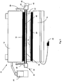
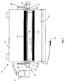
- a press brake 10 shown in FIG. 1 has an upper tool 12 that can be driven vertically downward against a lower tool 14 for working movement to bend a workpiece 16 resting on the lower tool 14.
- the upper tool 12 and the lower tool 14 have tool edges 18 and 20, which have a corresponding shape, in order to bend the workpiece 16 into a specific shape.
- an opening gap 22 between the upper tool 12 and the workpiece 16 is gradually closed.
- the press brake 10 is controlled by a controller 24 and may be activated by a footswitch 26, for example.
- the support arms 28 carry a light transmitter 30 and a spatially resolving receiver 32, which are parts of an opto-electronic safety device 33.
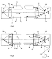
- the light transmitter 30 has a light source 36, for example a laser diode and a transmitting optics 38, which expands the transmitted light into a parallel light beam 34.
- the receiver 32 has a camera-like construction and has a spatially resolving two-dimensional light receiver 40, for example a CMOS matrix receiver, which is acted on by the light beam 34.
- a receiving optics 42 the light is imaged onto the light receiver 40.
- An optical filter 44 whose passband is tuned to the wavelength of the light emitter 36 can filter ambient light, thus improving the signal-to-noise ratio.
- the parallel expanded light beam 34 passes through the opening gap 22 along the lower edge 18 of the upper tool 12.
- the light beam 34 is a volume-shaped protection region 46 defined with marginal rays 62 and 64.
- an evaluation device 48 is provided, which, e.g. could be arranged on the receiver 32 or in the machine control 24. If there is an at least partial interruption of the light beam 34 within the protection area 46, as might be caused for example by an object 50 that could be a finger, this is recognized by the image on the spatial resolution light receiver 40 ( Figure 2).
- the evaluation device 48 conditions can be checked whether the object is e.g. a valid one or not. If a danger is finally detected in the evaluation device 48 as a result of the penetration of the object 50 into the protective area 46, a switching signal is triggered, for example for stopping the upper tool 12. This protects an operator from injury from the upper tool 12.
- the transmitter 30 and the receiver 32 are arranged such that a part of the tool edge 18 projects into the light beam 34.
- this image is recognized as permissible in the evaluation unit 48. This can e.g. be realized by storing a reference image or the like.
- the light beam 34 is widened such that it substantially fully illuminates the receiving optics of the receiver 32. So that the light receiver 40 is always hit even with vibrations, the cross section of the light beam 34 at the location of the light receiver 32 is smaller than the light receiver 40.
- the adjustment beam 58 that has entered the receiving optics is partially reflected at an optical interface 68.
- the reflected part 69 strikes a target disk 70 arranged in the second adjustment plate 54, which is designed as a ground glass.
- a target target 76 is marked on the ground glass 70, so that by rotating the receiver 32 in the directions of arrows 72 and 74 about two mutually perpendicular axes V and H, the receiver 32 is aligned so that the reflected portion 69 of the alignment beam 58 hits the target , Then the receiver is at least roughly aligned.
- the impact point 78 of the Justagelichtstrahls 58 is detected on the spatially resolving light receiver 40 and a deviation dx or dy determined by a target impact point 80.
- FIG. 7 shows a view of the detector surface 84 of the spatially resolving light receiver 40.
- the target impact point 80 is represented by a cross.
- the deviations dx and dy are represented by means of an electronic display 82.
- the display 82 is formed as a seven-segment display.
- the receiver 32 by further defined rotation in directions 72 and 74 are aligned until the impact point 78 is at the target impact point 80.
- Fig. 5 shows the first adjustment aperture 54 in plan view.
- the Justageblende 54 still two slot openings 86 and 88, passes through the light of the light beam 34, to form two auxiliary Justagelichtstrahlen. These are used for the coarse alignment as well as described above with respect to the adjustment beam 58.
- the auxiliary Justagestrahlen simplify the adjustment, since they are due to their larger cross-section due to the slot openings 86 and 88 at the beginning of the adjustment, when the safety device is still unadjusted to find better.
- the second Justageblende 54 also has two second slot openings 90 and 92, in which case, however, the longitudinal directions of the slot openings 90 and 92 are perpendicular to the longitudinal directions of the first slot openings 86 and 88. With approximately correct alignment of transmitter 30 and receiver 32 then only an approximately rectangular Operaquerschnit the auxiliary Justageestrahlen is transmitted.
- This part of the auxiliary adjustment jets also transmitted by the second adjustment aperture 54 has a special significance for the fine adjustment by means of the light receiver 40, as will be explained with reference to FIG. 7.
- the reference numerals 94 and 96 show the impact point of the auxiliary alignment light beams.
- a rotation of the receiver dr with respect to the Justagestrahlen can be determined with the auxiliary Justageestrahlen and a corresponding correction possible.
- the auxiliary adjustment beams also serve to facilitate locating the points of impingement, which are detected in the adjustment process only as adjustment light beams when they lie in a specific search region 98 of the detector surface 84.
- the corresponding impact points 78, 94 and 96 are measured by the light receiver 40 and the deviations dx, dy and the rotation dr are output on the display 82.
- the display 82 is designed as a seven-segment display, indicating the deviations or rather the directions of the deviations are very simple and visual representable and that according to the specifications of the following table No impact points detected Invalid pattern, too many points All impact points to the left of the target points All impact points above the target points All impact points left above the target points All impact points to the right of the target points _ All impact points below the target points All impact points right below the target points Impact points of the central Justierstrahls in the target but auxiliary Justageestrahlen left-twisted Impact points of the central Justierstrahls in the target but right-turned auxiliary Justageestrahlen Distance between the points of impact of the auxiliary alignment jets outside the tolerance (error) All impact points in the target points
- two third adjustment apertures 100 are provided, with the aid of which the safety device 33 can be aligned such that the light beam 34 runs exactly parallel to the tool edge 18.
- the two third adjustment apertures 100 are of identical design and, like the first justegraph end 52, have an aperture 156 for the central adjustment light beam and two slit apertures 186 and 188 for the auxiliary alignment light beams.
- the adjustment apertures 100 are mounted at the ends of the tool edge 18 in a predetermined manner, e.g. magnetically attached. 8 shows the press brake 10 with the safety system 33 according to the invention with mounted first, second and third adjustment apertures 52, 54 and 100.
- the light beam 34 is aligned exactly parallel to the edge of the tool. Thereafter, the receiver 32 can be accurately aligned, as described above.
Landscapes
- Engineering & Computer Science (AREA)
- General Engineering & Computer Science (AREA)
- Physics & Mathematics (AREA)
- Life Sciences & Earth Sciences (AREA)
- General Life Sciences & Earth Sciences (AREA)
- General Physics & Mathematics (AREA)
- Geophysics (AREA)
- Mechanical Engineering (AREA)
- Bending Of Plates, Rods, And Pipes (AREA)
- Presses And Accessory Devices Thereof (AREA)
- Air Bags (AREA)
- Length Measuring Devices By Optical Means (AREA)
Claims (15)
- Procédé pour ajuster un dispositif de sécurité (33) optoélectronique d'une machine faisant courir des risques, comme une presse plieuse (10) ou similaire, comprenant les étapes de procédé suivantes:- génération d'au moins un faisceau de lumière d'ajustage (58) parallèlement à l'axe (60) optique, mais à l'extérieur de celui-ci par positionnement d'un premier diaphragme d'ajustage (52) devant un émetteur de lumière (30),- positionnement d'un second diaphragme d'ajustage (54) devant un récepteur (32),- alignement de l'émetteur de lumière (30) de telle sorte que le faisceau de lumière d'ajustage (58) passe par une ouverture (66) du second diaphragme d'ajustage (54),- alignement du récepteur (32) de telle sorte que le faisceau de lumière d'ajustage (32) rencontre un point d'impact de consigne (80),caractérisé en ce que- le faisceau de lumière d'ajustage (58) passé à travers l'ouverture (66) du second diaphragme d'ajustage (54) est partiellement réfléchi et- le récepteur (32) est agencé d'abord à vu d'oeil par le fait qu'un point d'impact de la partie (69) réfléchie du faisceau de lumière d'ajustage (58) touche de façon visible une cible (70) et est axé sur une cible de consigne (76) et- en ce qu'ensuite le point d'impact (78) de la partie non réfléchie du faisceau d'ajustage (58) est déterminé électroniquement sur le récepteur (40) et est comparé dans une unité d'analyse (48) avec un point d'impact de consigne (80) sur le récepteur (40).
- Procédé selon la revendication 1, caractérisé en ce que le faisceau de lumière d'ajustage (58) présente une section de faisceau la plus petite possible, mais est visible sur la cible (70).
- Procédé selon la revendication 1 ou 2, caractérisé en ce que le faisceau de lumière d'ajustage (58) est partiellement réfléchi sur une surface limite (68) optique dans une optique de réception (42).
- Procédé selon l'une quelconque des revendications précédentes, caractérisé en ce que l'écart (dx, dy) du point d'impact (78) de la partie non réfléchie du faisceau d'ajustage (58) sur le récepteur de lumière (40) par rapport au point d'impact de consigne (80) est affiché sur un affichage (82) électronique.
- Procédé selon la revendication 4, caractérisé en ce que seule la direction de l'écart est affichée avec des symboles.
- Procédé selon l'une quelconque des revendications précédentes, caractérisé en ce que le faisceau de lumière d'ajustage (58) est orienté parallèlement à une arête d'outil (18) faisant courir le risque.
- Procédé selon la revendication 6, caractérisé en ce que des troisièmes diaphragmes d'ajustage (100) sont placés orientés sur les deux extrémités de l'arête d'outil (18) et le faisceau de lumière d'ajustage (58) est orienté de telle sorte qu'il traverse des ouvertures (156) des deux troisièmes diaphragmes d'ajustage (100).
- Procédé selon l'une quelconque des revendications précédentes, caractérisé en ce que deux faisceaux de lumière d'ajustage auxiliaires supplémentaires sont générés parallèlement au premier.
- Procédé selon l'une quelconque des revendications précédentes, caractérisé en ce que l'émetteur (30) et le récepteur (32) sont préajustés dans les phases respectives du processus d'ajustage à l'aide des deux faisceaux de lumière d'ajustage auxiliaires supplémentaires.
- Dispositif de sécurité optoélectronique pour une machine, en particulier une presse plieuse (10), avec un émetteur de lumière (30) avec optique d'émission (38) pour l'éclairage d'une zone de protection (46) avec lumière parallèle, un récepteur de lumière (40) à deux dimensions avec optique de réception (42, 44) pour la réception de la lumière d'émission, et avec un dispositif d'analyse et de commande (48) pour générer un signal de commutation, par exemple pour arrêter une première partie d'outil (12) lorsqu'un engagement dans la zone de protection (46) a été détecté par le récepteur de lumière (40) et la zone de protection (46) étant agencée parallèlement à une arête d'outil (18) du premier outil (12), raison pour laquelle l'émetteur de lumière (30) et le récepteur de lumière (40) sont montés sur les extrémités du premier outil (12), avec un premier obturateur d'ajustage (52) pour la pose sur l'émetteur de lumière (30) pour générer un faisceau de lumière d'ajustage (58) et avec un second diaphragme d'ajustage (54) à poser sur le récepteur de lumière (32), pour laisser passer le faisceau de lumière d'ajustage (52) dans l'optique de réception (42, 44), caractérisé en ce que dans l'optique de réception (42, 44) est prévue une surface limite (68) optique, pour la réflexion partielle du faisceau d'ajustage (58) et sur le second diaphragme d'ajustage (54) est disposé une cible (70) pour l'affichage optique de la partie (69) réfléchie du faisceau d'ajustage (58) pour le préajustage et en ce que l'unité d'analyse présente des moyens pour reconnaître et éditer un écart (dx, dy) d'un point d'impact (78) de la partie non réfléchie du faisceau de lumière d'ajustage (58) par rapport à un point d'impact de consigne (80).
- Dispositif de sécurité selon la revendication 10, caractérisé en ce que la cible est un verre dépoli (70).
- Dispositif de sécurité selon l'une quelconque des revendications 10 à 11, caractérisé en ce que deux autres faisceaux de lumière d'ajustage auxiliaires peuvent être générés au moyen du premier diaphragme d'ajustage (52).
- Dispositif de sécurité selon l'une quelconque des revendications précédentes 10 à 12, caractérisé en ce que deux troisièmes diaphragmes d'ajustage (100) conçus de façon identique sont prévus, pour l'orientation du faisceau de lumière parallèlement à l'arête d'outil (18).
- Dispositif de sécurité selon l'une quelconque des revendications 10 à 13, caractérisé en ce qu'un affichage (82) électronique est prévu pour l'affichage de la direction de l'écart du point d'impact (78) du faisceau d'ajustage (58) par rapport au point d'impact de consigne (80).
- Dispositif de sécurité selon la revendication 14, caractérisé en ce que l'affichage (82) est un affichage à sept segments.
Applications Claiming Priority (2)
| Application Number | Priority Date | Filing Date | Title |
|---|---|---|---|
| DE102004017285A DE102004017285A1 (de) | 2004-04-08 | 2004-04-08 | Verfahren zur Justage einer Sicherheitseinrichtung und optoelektronische Sicherheitseinrichtung |
| DE102004017285 | 2004-04-08 |
Publications (2)
| Publication Number | Publication Date |
|---|---|
| EP1589355A1 EP1589355A1 (fr) | 2005-10-26 |
| EP1589355B1 true EP1589355B1 (fr) | 2007-03-28 |
Family
ID=34933790
Family Applications (1)
| Application Number | Title | Priority Date | Filing Date |
|---|---|---|---|
| EP05003350A Expired - Lifetime EP1589355B1 (fr) | 2004-04-08 | 2005-02-17 | Méthode pour ajuster un système de sécurité et un système de sécurité optoéléctronique |
Country Status (3)
| Country | Link |
|---|---|
| EP (1) | EP1589355B1 (fr) |
| AT (1) | ATE358283T1 (fr) |
| DE (2) | DE102004017285A1 (fr) |
Families Citing this family (4)
| Publication number | Priority date | Publication date | Assignee | Title |
|---|---|---|---|---|
| DE102006056648A1 (de) * | 2006-11-29 | 2008-06-05 | Sick Ag | Opto-elektronischer Sensor |
| DE102007006306A1 (de) * | 2007-01-30 | 2008-07-31 | Pilz Gmbh & Co. Kg | Sicherheitseinrichtung für eine Maschine |
| DE102013205456B4 (de) * | 2013-03-27 | 2021-05-06 | Carl Zeiss Industrielle Messtechnik Gmbh | Ausrichtelement für einen optischen Abstandssensor, optische Sensoranordnung und Verfahren zur Ausrichtung eines optischen Abstandssensors |
| EP2939758B1 (fr) * | 2014-04-29 | 2019-01-16 | Schechtl Maschinenbau GmbH | Dispositif de déformation pour la déformation plastique d'un composant comprenant un système de sécurité |
Family Cites Families (7)
| Publication number | Priority date | Publication date | Assignee | Title |
|---|---|---|---|---|
| AUPN744696A0 (en) * | 1996-01-05 | 1996-02-01 | Appleyard, Thomas John | Safety apparatus and protection method for machines |
| DE19717299C2 (de) * | 1996-08-20 | 2002-03-14 | Fiessler Elektronik Ohg | Schutzeinrichtung für Maschinen,insbesondere für Abkantpressen, Schneidemaschinen oder Stanzmaschinen |
| DE10106755B4 (de) * | 2001-02-14 | 2006-05-24 | Leuze Electronic Gmbh & Co Kg | Optoelekronische Vorrichtung |
| DE10114784A1 (de) * | 2001-03-26 | 2002-10-10 | Sick Ag | Vorrichtung zur Überwachung eines Schutzfeldes |
| DE10138223A1 (de) * | 2001-08-03 | 2003-02-20 | Sick Ag | Verfahren zur Steuerung eines Lichtgitters |
| US7448241B2 (en) * | 2002-06-11 | 2008-11-11 | Davies Kevin S | Safety system |
| DE20317622U1 (de) * | 2003-11-14 | 2004-02-12 | Sick Ag | Lichtschranke |
-
2004
- 2004-04-08 DE DE102004017285A patent/DE102004017285A1/de not_active Withdrawn
-
2005
- 2005-02-17 DE DE502005000511T patent/DE502005000511D1/de not_active Expired - Lifetime
- 2005-02-17 EP EP05003350A patent/EP1589355B1/fr not_active Expired - Lifetime
- 2005-02-17 AT AT05003350T patent/ATE358283T1/de not_active IP Right Cessation
Also Published As
| Publication number | Publication date |
|---|---|
| ATE358283T1 (de) | 2007-04-15 |
| DE102004017285A1 (de) | 2005-10-27 |
| DE502005000511D1 (de) | 2007-05-10 |
| EP1589355A1 (fr) | 2005-10-26 |
Similar Documents
| Publication | Publication Date | Title |
|---|---|---|
| EP1589279B9 (fr) | Procédé pour la sécurité d'une machine-outil et capteur optoélectronique pour la mise en oeuvre d'un tel procédé | |
| EP1993081B1 (fr) | Dispositif de capteur optoélectronique et procédé de surveillance d'une zone de surveillance | |
| EP1394504B1 (fr) | Rideau optique | |
| DE10327388B4 (de) | Schutzeinrichtung | |
| EP1734383B1 (fr) | Barrière lumineuse destinée à la mesure d'un objet | |
| EP1246148B1 (fr) | Dispositif de surveillance d'une zone de protection | |
| EP1566588B1 (fr) | Rideau de lumière ou barrière optique avec dispositif d'alignement | |
| EP1437542B1 (fr) | Barrière optique et son procédé de réglage | |
| DE10247136A1 (de) | Schutzvorrichtung zur Überwachung eines mit einem Bauteil zu bewegenden Schutzbereichs | |
| DE102006050189B4 (de) | Lichtgitter mit Ausrichtlichtsender und Verfahren zum Ausrichten | |
| DE202008004711U1 (de) | Lichtgitterkaskadierung | |
| EP1813961A2 (fr) | Dispositif destiné à la surveillance optoélectronique d'objets | |
| EP1531345B1 (fr) | Aide d'alignement pour appareils d'arrêt de lumière | |
| EP1589355A1 (fr) | Méthode pour ajuster un système de sécurité et un système de sécurité optoéléctronique | |
| DE102006053359B4 (de) | Optoelektronische Sensoranordnung und Verfahren zum Justieren einer optoelektronischen Sensoranordnung | |
| EP2147729B1 (fr) | Dispositif de déformation | |
| EP1748246B1 (fr) | Dispositif de protection pour machines telles que presses-plieuses, découpeuses, machines à estamper ou analogues | |
| DE10314852A1 (de) | Optoelektronische Zugangsabsicherung | |
| DE102009009386B4 (de) | Optoelektronische Vorrichtung | |
| DE102004025751A1 (de) | Justiervorrichtung insbesondere für Lichtschranken oder Lichtgitter und Verfahren zur Justage | |
| EP2144091B1 (fr) | Optique à rayonnement double pour barrières lumineuses | |
| EP1686398B1 (fr) | Capteur optoélectronique | |
| EP2746820B1 (fr) | Capteur optique | |
| WO2015121030A1 (fr) | Procédé de réalisation d'un cordon de soudure au laser entre des éléments comprenant un élément sphérique ou sphéroïde, et assemblage d'éléments correspondant | |
| EP3770647A1 (fr) | Agencement de barrière lumineuse et procédé d'ajustement d'un agencement de barrière lumineuse |
Legal Events
| Date | Code | Title | Description |
|---|---|---|---|
| PUAI | Public reference made under article 153(3) epc to a published international application that has entered the european phase |
Free format text: ORIGINAL CODE: 0009012 |
|
| AK | Designated contracting states |
Kind code of ref document: A1 Designated state(s): AT BE BG CH CY CZ DE DK EE ES FI FR GB GR HU IE IS IT LI LT LU MC NL PL PT RO SE SI SK TR |
|
| AX | Request for extension of the european patent |
Extension state: AL BA HR LV MK YU |
|
| 17P | Request for examination filed |
Effective date: 20051210 |
|
| AKX | Designation fees paid |
Designated state(s): AT BE BG CH CY CZ DE DK EE ES FI FR GB GR HU IE IS IT LI LT LU MC NL PL PT RO SE SI SK TR |
|
| GRAP | Despatch of communication of intention to grant a patent |
Free format text: ORIGINAL CODE: EPIDOSNIGR1 |
|
| RAP1 | Party data changed (applicant data changed or rights of an application transferred) |
Owner name: SICK AG |
|
| GRAS | Grant fee paid |
Free format text: ORIGINAL CODE: EPIDOSNIGR3 |
|
| GRAA | (expected) grant |
Free format text: ORIGINAL CODE: 0009210 |
|
| AK | Designated contracting states |
Kind code of ref document: B1 Designated state(s): AT BE BG CH CY CZ DE DK EE ES FI FR GB GR HU IE IS IT LI LT LU MC NL PL PT RO SE SI SK TR |
|
| PG25 | Lapsed in a contracting state [announced via postgrant information from national office to epo] |
Ref country code: PL Free format text: LAPSE BECAUSE OF FAILURE TO SUBMIT A TRANSLATION OF THE DESCRIPTION OR TO PAY THE FEE WITHIN THE PRESCRIBED TIME-LIMIT Effective date: 20070328 Ref country code: FI Free format text: LAPSE BECAUSE OF FAILURE TO SUBMIT A TRANSLATION OF THE DESCRIPTION OR TO PAY THE FEE WITHIN THE PRESCRIBED TIME-LIMIT Effective date: 20070328 Ref country code: SI Free format text: LAPSE BECAUSE OF FAILURE TO SUBMIT A TRANSLATION OF THE DESCRIPTION OR TO PAY THE FEE WITHIN THE PRESCRIBED TIME-LIMIT Effective date: 20070328 Ref country code: NL Free format text: LAPSE BECAUSE OF FAILURE TO SUBMIT A TRANSLATION OF THE DESCRIPTION OR TO PAY THE FEE WITHIN THE PRESCRIBED TIME-LIMIT Effective date: 20070328 |
|
| REG | Reference to a national code |
Ref country code: GB Ref legal event code: FG4D Free format text: NOT ENGLISH |
|
| REG | Reference to a national code |
Ref country code: CH Ref legal event code: EP |
|
| REF | Corresponds to: |
Ref document number: 502005000511 Country of ref document: DE Date of ref document: 20070510 Kind code of ref document: P |
|
| REG | Reference to a national code |
Ref country code: IE Ref legal event code: FG4D Free format text: LANGUAGE OF EP DOCUMENT: GERMAN |
|
| PG25 | Lapsed in a contracting state [announced via postgrant information from national office to epo] |
Ref country code: SE Free format text: LAPSE BECAUSE OF FAILURE TO SUBMIT A TRANSLATION OF THE DESCRIPTION OR TO PAY THE FEE WITHIN THE PRESCRIBED TIME-LIMIT Effective date: 20070628 |
|
| PG25 | Lapsed in a contracting state [announced via postgrant information from national office to epo] |
Ref country code: ES Free format text: LAPSE BECAUSE OF FAILURE TO SUBMIT A TRANSLATION OF THE DESCRIPTION OR TO PAY THE FEE WITHIN THE PRESCRIBED TIME-LIMIT Effective date: 20070709 |
|
| PG25 | Lapsed in a contracting state [announced via postgrant information from national office to epo] |
Ref country code: IS Free format text: LAPSE BECAUSE OF FAILURE TO SUBMIT A TRANSLATION OF THE DESCRIPTION OR TO PAY THE FEE WITHIN THE PRESCRIBED TIME-LIMIT Effective date: 20070728 |
|
| PG25 | Lapsed in a contracting state [announced via postgrant information from national office to epo] |
Ref country code: PT Free format text: LAPSE BECAUSE OF FAILURE TO SUBMIT A TRANSLATION OF THE DESCRIPTION OR TO PAY THE FEE WITHIN THE PRESCRIBED TIME-LIMIT Effective date: 20070828 |
|
| NLV1 | Nl: lapsed or annulled due to failure to fulfill the requirements of art. 29p and 29m of the patents act | ||
| GBV | Gb: ep patent (uk) treated as always having been void in accordance with gb section 77(7)/1977 [no translation filed] |
Effective date: 20070328 |
|
| EN | Fr: translation not filed | ||
| PG25 | Lapsed in a contracting state [announced via postgrant information from national office to epo] |
Ref country code: SK Free format text: LAPSE BECAUSE OF FAILURE TO SUBMIT A TRANSLATION OF THE DESCRIPTION OR TO PAY THE FEE WITHIN THE PRESCRIBED TIME-LIMIT Effective date: 20070328 |
|
| REG | Reference to a national code |
Ref country code: IE Ref legal event code: FD4D |
|
| PG25 | Lapsed in a contracting state [announced via postgrant information from national office to epo] |
Ref country code: CZ Free format text: LAPSE BECAUSE OF FAILURE TO SUBMIT A TRANSLATION OF THE DESCRIPTION OR TO PAY THE FEE WITHIN THE PRESCRIBED TIME-LIMIT Effective date: 20070328 Ref country code: RO Free format text: LAPSE BECAUSE OF FAILURE TO SUBMIT A TRANSLATION OF THE DESCRIPTION OR TO PAY THE FEE WITHIN THE PRESCRIBED TIME-LIMIT Effective date: 20070328 |
|
| PG25 | Lapsed in a contracting state [announced via postgrant information from national office to epo] |
Ref country code: IE Free format text: LAPSE BECAUSE OF FAILURE TO SUBMIT A TRANSLATION OF THE DESCRIPTION OR TO PAY THE FEE WITHIN THE PRESCRIBED TIME-LIMIT Effective date: 20070328 Ref country code: DK Free format text: LAPSE BECAUSE OF FAILURE TO SUBMIT A TRANSLATION OF THE DESCRIPTION OR TO PAY THE FEE WITHIN THE PRESCRIBED TIME-LIMIT Effective date: 20070328 |
|
| PLBE | No opposition filed within time limit |
Free format text: ORIGINAL CODE: 0009261 |
|
| STAA | Information on the status of an ep patent application or granted ep patent |
Free format text: STATUS: NO OPPOSITION FILED WITHIN TIME LIMIT |
|
| PG25 | Lapsed in a contracting state [announced via postgrant information from national office to epo] |
Ref country code: LT Free format text: LAPSE BECAUSE OF FAILURE TO SUBMIT A TRANSLATION OF THE DESCRIPTION OR TO PAY THE FEE WITHIN THE PRESCRIBED TIME-LIMIT Effective date: 20070328 |
|
| 26N | No opposition filed |
Effective date: 20080102 |
|
| PG25 | Lapsed in a contracting state [announced via postgrant information from national office to epo] |
Ref country code: GB Free format text: LAPSE BECAUSE OF FAILURE TO SUBMIT A TRANSLATION OF THE DESCRIPTION OR TO PAY THE FEE WITHIN THE PRESCRIBED TIME-LIMIT Effective date: 20070328 Ref country code: FR Free format text: LAPSE BECAUSE OF FAILURE TO SUBMIT A TRANSLATION OF THE DESCRIPTION OR TO PAY THE FEE WITHIN THE PRESCRIBED TIME-LIMIT Effective date: 20071116 Ref country code: GR Free format text: LAPSE BECAUSE OF FAILURE TO SUBMIT A TRANSLATION OF THE DESCRIPTION OR TO PAY THE FEE WITHIN THE PRESCRIBED TIME-LIMIT Effective date: 20070629 |
|
| BERE | Be: lapsed |
Owner name: SICK A.G. Effective date: 20080228 |
|
| PG25 | Lapsed in a contracting state [announced via postgrant information from national office to epo] |
Ref country code: MC Free format text: LAPSE BECAUSE OF NON-PAYMENT OF DUE FEES Effective date: 20080228 |
|
| PG25 | Lapsed in a contracting state [announced via postgrant information from national office to epo] |
Ref country code: FR Free format text: LAPSE BECAUSE OF FAILURE TO SUBMIT A TRANSLATION OF THE DESCRIPTION OR TO PAY THE FEE WITHIN THE PRESCRIBED TIME-LIMIT Effective date: 20070328 |
|
| PG25 | Lapsed in a contracting state [announced via postgrant information from national office to epo] |
Ref country code: EE Free format text: LAPSE BECAUSE OF FAILURE TO SUBMIT A TRANSLATION OF THE DESCRIPTION OR TO PAY THE FEE WITHIN THE PRESCRIBED TIME-LIMIT Effective date: 20070328 |
|
| PG25 | Lapsed in a contracting state [announced via postgrant information from national office to epo] |
Ref country code: BE Free format text: LAPSE BECAUSE OF NON-PAYMENT OF DUE FEES Effective date: 20080228 |
|
| PG25 | Lapsed in a contracting state [announced via postgrant information from national office to epo] |
Ref country code: CY Free format text: LAPSE BECAUSE OF FAILURE TO SUBMIT A TRANSLATION OF THE DESCRIPTION OR TO PAY THE FEE WITHIN THE PRESCRIBED TIME-LIMIT Effective date: 20070328 |
|
| PG25 | Lapsed in a contracting state [announced via postgrant information from national office to epo] |
Ref country code: BG Free format text: LAPSE BECAUSE OF FAILURE TO SUBMIT A TRANSLATION OF THE DESCRIPTION OR TO PAY THE FEE WITHIN THE PRESCRIBED TIME-LIMIT Effective date: 20070628 |
|
| REG | Reference to a national code |
Ref country code: CH Ref legal event code: PL |
|
| PG25 | Lapsed in a contracting state [announced via postgrant information from national office to epo] |
Ref country code: CH Free format text: LAPSE BECAUSE OF NON-PAYMENT OF DUE FEES Effective date: 20090228 Ref country code: LI Free format text: LAPSE BECAUSE OF NON-PAYMENT OF DUE FEES Effective date: 20090228 |
|
| PGFP | Annual fee paid to national office [announced via postgrant information from national office to epo] |
Ref country code: IT Payment date: 20100223 Year of fee payment: 6 |
|
| PGFP | Annual fee paid to national office [announced via postgrant information from national office to epo] |
Ref country code: AT Payment date: 20100217 Year of fee payment: 6 |
|
| PG25 | Lapsed in a contracting state [announced via postgrant information from national office to epo] |
Ref country code: HU Free format text: LAPSE BECAUSE OF FAILURE TO SUBMIT A TRANSLATION OF THE DESCRIPTION OR TO PAY THE FEE WITHIN THE PRESCRIBED TIME-LIMIT Effective date: 20070929 Ref country code: LU Free format text: LAPSE BECAUSE OF NON-PAYMENT OF DUE FEES Effective date: 20080217 |
|
| PG25 | Lapsed in a contracting state [announced via postgrant information from national office to epo] |
Ref country code: AT Free format text: LAPSE BECAUSE OF NON-PAYMENT OF DUE FEES Effective date: 20110217 |
|
| PG25 | Lapsed in a contracting state [announced via postgrant information from national office to epo] |
Ref country code: IT Free format text: LAPSE BECAUSE OF NON-PAYMENT OF DUE FEES Effective date: 20110217 |
|
| PGFP | Annual fee paid to national office [announced via postgrant information from national office to epo] |
Ref country code: TR Payment date: 20120215 Year of fee payment: 8 |
|
| PGFP | Annual fee paid to national office [announced via postgrant information from national office to epo] |
Ref country code: DE Payment date: 20130220 Year of fee payment: 9 |
|
| REG | Reference to a national code |
Ref country code: DE Ref legal event code: R119 Ref document number: 502005000511 Country of ref document: DE |
|
| REG | Reference to a national code |
Ref country code: DE Ref legal event code: R119 Ref document number: 502005000511 Country of ref document: DE Effective date: 20140902 |
|
| PG25 | Lapsed in a contracting state [announced via postgrant information from national office to epo] |
Ref country code: DE Free format text: LAPSE BECAUSE OF NON-PAYMENT OF DUE FEES Effective date: 20140902 |
|
| PG25 | Lapsed in a contracting state [announced via postgrant information from national office to epo] |
Ref country code: TR Free format text: LAPSE BECAUSE OF NON-PAYMENT OF DUE FEES Effective date: 20140217 |