EP1589239A1 - Dispositif de charniere et dispositif electronique utilisant ce dispositif de charniere - Google Patents
Dispositif de charniere et dispositif electronique utilisant ce dispositif de charniere Download PDFInfo
- Publication number
- EP1589239A1 EP1589239A1 EP03780746A EP03780746A EP1589239A1 EP 1589239 A1 EP1589239 A1 EP 1589239A1 EP 03780746 A EP03780746 A EP 03780746A EP 03780746 A EP03780746 A EP 03780746A EP 1589239 A1 EP1589239 A1 EP 1589239A1
- Authority
- EP
- European Patent Office
- Prior art keywords
- cam
- biasing
- engagement
- closing
- coupled
- Prior art date
- Legal status (The legal status is an assumption and is not a legal conclusion. Google has not performed a legal analysis and makes no representation as to the accuracy of the status listed.)
- Withdrawn
Links
Images











Classifications
-
- H—ELECTRICITY
- H04—ELECTRIC COMMUNICATION TECHNIQUE
- H04B—TRANSMISSION
- H04B1/00—Details of transmission systems, not covered by a single one of groups H04B3/00 - H04B13/00; Details of transmission systems not characterised by the medium used for transmission
- H04B1/38—Transceivers, i.e. devices in which transmitter and receiver form a structural unit and in which at least one part is used for functions of transmitting and receiving
-
- H—ELECTRICITY
- H04—ELECTRIC COMMUNICATION TECHNIQUE
- H04M—TELEPHONIC COMMUNICATION
- H04M1/00—Substation equipment, e.g. for use by subscribers
- H04M1/02—Constructional features of telephone sets
- H04M1/0202—Portable telephone sets, e.g. cordless phones, mobile phones or bar type handsets
- H04M1/0206—Portable telephones comprising a plurality of mechanically joined movable body parts, e.g. hinged housings
- H04M1/0208—Portable telephones comprising a plurality of mechanically joined movable body parts, e.g. hinged housings characterized by the relative motions of the body parts
- H04M1/0214—Foldable telephones, i.e. with body parts pivoting to an open position around an axis parallel to the plane they define in closed position
- H04M1/0216—Foldable in one direction, i.e. using a one degree of freedom hinge
-
- F—MECHANICAL ENGINEERING; LIGHTING; HEATING; WEAPONS; BLASTING
- F16—ENGINEERING ELEMENTS AND UNITS; GENERAL MEASURES FOR PRODUCING AND MAINTAINING EFFECTIVE FUNCTIONING OF MACHINES OR INSTALLATIONS; THERMAL INSULATION IN GENERAL
- F16C—SHAFTS; FLEXIBLE SHAFTS; ELEMENTS OR CRANKSHAFT MECHANISMS; ROTARY BODIES OTHER THAN GEARING ELEMENTS; BEARINGS
- F16C11/00—Pivots; Pivotal connections
- F16C11/04—Pivotal connections
-
- H—ELECTRICITY
- H04—ELECTRIC COMMUNICATION TECHNIQUE
- H04M—TELEPHONIC COMMUNICATION
- H04M1/00—Substation equipment, e.g. for use by subscribers
- H04M1/02—Constructional features of telephone sets
- H04M1/0202—Portable telephone sets, e.g. cordless phones, mobile phones or bar type handsets
- H04M1/0206—Portable telephones comprising a plurality of mechanically joined movable body parts, e.g. hinged housings
- H04M1/0208—Portable telephones comprising a plurality of mechanically joined movable body parts, e.g. hinged housings characterized by the relative motions of the body parts
- H04M1/0214—Foldable telephones, i.e. with body parts pivoting to an open position around an axis parallel to the plane they define in closed position
- H04M1/0216—Foldable in one direction, i.e. using a one degree of freedom hinge
- H04M1/0218—The hinge comprising input and/or output user interface means
Definitions
- the present invention relates to a hinge device and an electronic instrument using the hinge device.
- a portable phone as a typical example of a portable electronic instrument is of collapsible type in which a portable phone body (a body portion and a joint portion) is collapsible.
- This collapsible type is popular in aspects of preventing a switch from malfunctioning, making the phone compact when the phone is collapsed (to keep a display area sufficient), a variety of designs and the like.
- the present applicant has made further experiments and studies repeatedly with respect to the above-described hinge device and has developed a novel hinge device and an electronic instrument using the hinge device which is more valuable as a commercial product.
- the present invention relates to a hinge device for pivoting a first member 1 and a second member 2 to be rotatably opened and closed, characterized in that when the second member 2 kept under a coupled and closed condition is opened to the first member 1, in a rotational range A1 from the coupled and closed position P1 to a predetermined open angle position P2 rotated in an open direction, a closing rotational biasing effect is generated for automatically closing the second member 2 to the coupled and closed position P1 relative to the first member 1, and when the second member 2 is manually rotated in the open direction exceeding the predetermined open angle position P2 to the first member 1, an open rotational biasing effect is generated for automatically opening the second member 2 to a predetermined open angle position P3 relative to the first member 1.
- the invention relates to a hinge device for pivoting a first member 1 and a second member 2 to be rotatably opened and closed, characterized in that when the second member 2 kept under a coupled and closed condition is opened to the first member 1, in a rotational range A1 from the coupled and closed position P1 to a predetermined open angle position P2 rotated in an open direction, a closing rotational biasing effect is generated for automatically closing the second member 2 to the coupled and closed position P1 relative to the first member 1, when the second member 2 is manually rotated in the open direction exceeding the predetermined open angle position P2 to the first member 1, an open rotational biasing effect is generated for automatically opening the second member 2 to a predetermined open angle position P3 relative to the first member 1, and in a rotational range A2 to the predetermined open angle position P2 rotated in the closing direction from a position where the second member 2 is opened to the first member 1, a free stop effect is generated for holding the second member 2 at any desired open angle position relative to the first member 1.
- the invention relates to a hinge device for pivoting a first member 1 and a second member 2 to be rotatably opened and closed, characterized by comprising a closing structure portion 5 for generating a close rotational biasing effect for automatically closing the second member 2 to the coupled and closed position P1 relative to the first member 1 in a rotational range A1 from the coupled and closed position P1 to a predetermined open angle position P2 rotated in an open direction when the second member 2 kept under a coupled and closed condition is opened to the first member 1, an opening structure portion 6 for generating an open rotational biasing effect for automatically opening the second member 2 to a predetermined open angle position P3 relative to the first member 1, by biasing said closing structure portion in the rotational direction when the second member 2 is manually rotated in the open direction exceeding the predetermined open angle position P2 to the first member 1, and a rotation preventing structure portion 7 for releaseably retaining at said closing structure portion 5 and preventing the rotation of the closing structure portion 6 in the open direction by said opening structure portion 6, wherein a retention force of the
- the invention relates to the hinge device according to claim 3, characterized in that a depression button portion 26 for releasing the retention of the rotation preventing structure portion 7 to said closing structure portion 5 is provided in said rotation preventing structure portion 7.
- the invention relates to a hinge device for pivoting a first member 1 and a second member 2 to be rotatably opened and closed, characterized by comprising a closing structure portion 5 for generating a close rotational basing effect for automatically closing the second member 2 to the coupled and closed position P1 relative to the first member 1 in a rotational range A1 from the coupled and closed position P1 to a predetermined open angle position P2 rotated in an open direction when the second member 2 kept under a coupled and closed condition is opened to the first member 1, an opening structure portion 6 for generating an open rotational biasing effect for automatically opening the second member 2 to a predetermined open angle position P3 relative to the first member 1, by biasing said closing structure portion 5 in the rotational direction when the second member 2 is manually rotated in the open direction exceeding the predetermined open angle position P2 to the first member 1, and a retainer member 8 for releaseably retaining to said closing structure portion 5, wherein under the condition that said retainer member 8 is retained at the closing structure portion 5, the rotation of the closing structure portion 5 by said
- the invention relates to a hinge device for pivoting a first member 1 and a second member 2 to be rotatably opened and closed, characterized by comprising a first joint member 3 coupled with the first member 1 in a rotation prevented condition and a second joint member 4 coupled relatively rotatably to the first joint member 3 and coupled with the second member 2 in a rotation prevented condition, wherein a cam portion 10 is provided to either one of the first joint member 3 and the second joint member 4, a cam engagement portion 11 which engages with the cam portion 10 is provided to the other, at least one of the cam portion 10 and the cam engagement portion 11 is provided slidably in the engagement and disengagement direction, an engagement biasing member 12 is provided for biasing at least one of the cam portion 10 and the cam engagement portion 11 in the engagement direction, when the second member 2 kept under the coupled and closed condition is opened to the first member 1, in a rotational range A1 to a predetermined open angle position P2 rotated in the open direction from the coupled and closed position P1, the cam portion 10 and the cam engagement portion 11 are
- the invention relates to a hinge device for pivoting a first member 1 and a second member 2 to be rotatably opened and closed, characterized by comprising a first joint member 3 coupled with the first member 1 in a rotation prevented condition and a second joint member 4 coupled relatively rotatably to the first joint member 3 and coupled with the second member 2 in a rotation prevented condition, wherein a cam portion 10 is provided to either one of the first joint member 3 and the second joint member 4, a cam engagement portion 11 which engages with the cam portion 10 is provided to the other, at least one of the cam portion 10 and the cam engagement portion 11 is provided slidably in the engagement and disengagement direction, an engagement biasing member 12 is provided for biasing at least one of the cam portion 10 and the cam engagement portion 11 in the engagement direction, when the second member 2 kept under the coupled and closed condition is opened to the first member 1, in a rotational range A1 to a predetermined open angle position P2 rotated in the open direction from the coupled and closed position P1, the cam portion 10 and the cam engagement portion 11 are
- the invention relates to the hinge device according to any one of claims 5 to 7, further characterized in that an engagement concave portion 9 for fitting and retaining said retainer member 8 is provided in said cam portion 10 or said cam engagement portion 11, and a taper surface 8a is formed in an insertion portion of the retainer member 8 to be inserted into said engagement concave portion 9 whereby a retention force of the retainer member 8 to said engagement concave portion 9 is set up to such a retention force that the retainer member 8 is disengaged from the cam portion 10 or the cam engagement portion 11 when the second member 2 is manually rotated relative to the first member 1 in the open direction exceeding the predetermined open angle position P2 against the closing rotation biasing force by the cam portion 10 and the cam engagement portion 11.
- the invention relates to the hinge device according to any one of claims 5 to 7, further characterized in that said retainer member 8 is slidingly moved by a depression operation of a depression button portion 26 so that the retention to said closing structure portion 5 is released.
- the invention relates to a hinge device for pivoting a first member 1 and a second member 2 to be rotatably opened and closed, characterized by comprising a first hinge member H1 provided in a first pivot portion 25A provided in either one of right and left positions of a pivot joint portion 25 between said first member 1 and said second member 2 and a second hinge member H2 provided in a second pivot portion 25B provided in the other position, wherein a closing structure portion 5 is provided in said first hinge member H1 for generating a closing rotation biasing effect for automatically closing the second member 2 to the first member 1 to a coupled and closed position P1 in a rotational range A1 to a predetermined open angle position P2 rotated in an opening direction from the coupled and closed position P1 when the second member 2 kept under the coupled and closed condition is opened relative to said first member 1, an opening structure portion 6 is provided in said second hinge member H2 for generating an opening rotation biasing effect for automatically opening the second member 2 to the first member 1 to a predetermined open angle position P3 by biasing the closing
- the invention relates to a hinge device for pivoting a first member 1 and a second member 2 to be rotatably opened and closed, characterized by comprising a first hinge member H1 provided in a first pivot portion 25A provided in either one of right and left positions of a pivot joint portion 25 between said first member 1 and said second member 2 and a second hinge member H2 provided in a second pivot portion 25B provided in the other position, wherein a closing structure portion 5 is provided in said first hinge member H1 for generating a closing rotation biasing effect for automatically closing the second member 2 to the first member 1 to a coupled and closed position P1 in a rotational range A1 to a predetermined open angle position P2 rotated in an opening direction from the coupled and closed position P1 when the second member 2 kept under the coupled and closed condition is opened relative to said first member 1, an opening structure portion 6 is provided in said second hinge member H2 for generating an opening rotation biasing effect for automatically opening the second member 2 to the first member 1 to a predetermined open angle position P3 by biasing the closing
- the invention relates to a hinge device for pivoting a first member 1 and a second member 2 to be rotatably opened and closed, characterized by comprising a first hinge member H1 provided in a first pivot portion 25A provided in either one of right and left positions of a pivot joint portion 25 between said first member 1 and said second member 2 and a second hinge member H2 provided in a second pivot portion 25B provided in the other position, wherein said first hinge member H1 is composed of a first joint member 3 coupled to the first member 1 or the second member 2 and a second joint member 4 coupled to the second member 2 or the first member 1, a closing structure portion 5 is provided in said first hinge member H1 for generating a closing rotation biasing effect for automatically closing the second member 2 to the first member 1 to a coupled and closed position P1 in a rotational range A1 to a predetermined open angle position P2 rotated in an opening direction from the coupled and closed position P1 when the second member 2 kept under the coupled and closed condition is opened relative to said first member 1, an opening structure portion 6 is
- the invention relates to a hinge device for pivoting a first member 1 and a second member 2 to be rotatably opened and closed, characterized by comprising a first hinge member H1 provided in a first pivot portion 25A provided in either one of right and left positions of a pivot joint portion 25 between said first member 1 and said second member 2 and a second hinge member H2 provided in a second pivot portion 25B provided in the other position, wherein said first hinge member H1 is composed of a first joint member 3 coupled to the first member 1 or the second member 2 and a second joint member 4 coupled to the second member 2 or the first member 1, a cam portion 10 is provided to either one of the first joint member 3 and the second joint member 4 of said first hinge member H1, a cam engagement portion 11 which engages with the cam portion 10 is provided to the other, at least one of the cam portion 10 and the cam engagement portion 11 is provided slidably in the engagement and disengagement direction, an engagement biasing member 12 is provided for biasing at least one of the cam portion 10 and the cam engagement portion 11 in the first
- the invention relates to a hinge device for pivoting a first member 1 and a second member 2 to be rotatably opened and closed, characterized by comprising a first hinge member H1 provided in a first pivot portion 25A provided in either one of right and left positions of a pivot joint portion 25 between said first member 1 and said second member 2 and a second hinge member H2 provided in a second pivot portion 25B provided in the other position, wherein said first hinge member H1 is composed of a first joint member 3 coupled to the first member 1 or the second member 2 and a second joint member 4 coupled to the second member 2 or the first member 1, a cam portion 10 is provided to either one of the first joint member 3 and the second joint member 4 of said first hinge member H1, a cam engagement portion 11 which engages with the cam portion 10 is provided to the other, at least one of the cam portion 10 and the cam engagement portion 11 is provided slidably in the engagement and disengagement direction, an engagement biasing member 12 is provided for biasing at least one of the cam portion 10 and the cam engagement portion 11 in the first
- the invention relates to a hinge device for pivoting a first member 1 and a second member 2 to be rotatably opened and closed, characterized by comprising a first hinge member H1 provided in a first pivot portion 25A provided in either one of right and left positions of a pivot joint portion 25 between said first member 1 and said second member 2 and a second hinge member H2 provided in a second pivot portion 25B provided in the other position, wherein a closing structure portion 5 is provided in said first hinge member H1 for generating a closing rotation biasing effect for automatically closing the second member 2 to the first member 1 to a coupled and closed position P1 in a rotational range A1 to a predetermined open angle position P2 rotated in an opening direction from the coupled and closed position P1 when the second member 2 kept under the coupled and closed condition is opened relative to said first member 1, and an opening structure portion 6 is provided in said second hinge member H2 for generating an opening rotation biasing effect for automatically opening the second member 2 to the first member 1 to a predetermined open angle position P3 by biasing the
- the invention relates to a hinge device for pivoting a first member 1 and a second member 2 to be rotatably opened and closed, characterized by comprising a first hinge member H1 provided in a first pivot portion 25A provided in either one of right and left positions of a pivot joint portion 25 between said first member 1 and said second member 2 and a second hinge member H2 provided in a second pivot portion 25B provided in the other position, wherein a closing structure portion 5 is provided in said first hinge member H1 for generating a closing rotation biasing effect for automatically closing the second member 2 to the first member 1 to a coupled and closed position P1 in a rotational range A1 to a predetermined open angle position P2 rotated in an opening direction from the coupled and closed position P1 when the second member 2 kept under the coupled and closed condition is opened relative to said first member 1, an opening structure portion 6 is provided in said second hinge member H2 for generating an opening rotation biasing effect for automatically opening the second member 2 to the first member 1 to a predetermined open angle position P3 by biasing the closing
- the invention relates to a hinge device for pivoting a first member 1 and a second member 2 to be rotatably opened and closed, characterized by comprising a first hinge member H1 provided in a first pivot portion 25A provided in either one of right and left positions of a pivot joint portion 25 between said first member 1 and said second member 2 and a second hinge member H2 provided in a second pivot portion 25B provided in the other position, wherein a closing structure portion 5 is provided in said first hinge member H1 for generating a closing rotation biasing effect for automatically closing the second member 2 to the first member 1 to a coupled and closed position P1 in a rotational range A1 to a predetermined open angle position P2 rotated in an opening direction from the coupled and closed position P1 when the second member 2 kept under the coupled and closed condition is opened relative to said first member 1, an opening structure portion 6 is provided in said second hinge member H2 for generating an opening rotation biasing effect for automatically opening the second member 2 to the first member 1 to a predetermined open angle position P3 by biasing said closing
- the invention relates to a hinge device for pivoting a first member 1 and a second member 2 to be rotatably opened and closed, characterized by comprising a first hinge member H1 provided in a first pivot portion 25A provided in either one of right and left positions of a pivot joint portion 25 between said first member 1 and said second member 2 and a second hinge member H2 provided in a second pivot portion 25B provided in the other position, wherein said first hinge member H1 is composed of a first joint member 3 coupled with the first member 1 or the second member 2 and a second joint member 4 coupled with the second member 2 or the first member 1, a closing structure portion 5 is provided in said first hinge member H1 for generating a closing rotation biasing effect for automatically closing the second member 2 to the first member 1 to a coupled and closed position P1 in a rotational range A1 to a predetermined open angle position P2 rotated in an opening direction from the coupled and closed position P1 when the second member 2 kept under the coupled and closed condition is opened relative to said first member 1, an opening structure portion 6 is
- the invention relates to a hinge device for pivoting a first member 1 and a second member 2 to be rotatably opened and closed, characterized by comprising a first hinge member H1 provided in a first pivot portion 25A provided in either one of right and left positions of a pivot joint portion 25 between said first member 1 and said second member 2 and a second hinge member H2 provided in a second pivot portion 25B provided in the other position, wherein said first hinge member H1 is composed of a first joint member 3 coupled with the first member 1 or the second member 2 and a second joint member 4 coupled with the second member 2 or the first member 1, a cam portion 10 is provided to either one of the first joint member 3 and the second joint member 4 of said first hinge member H1, a cam engagement portion 11 which engages with the cam portion 10 is provided to the other, at least one of the cam portion 10 and the cam engagement portion 11 is provided slidably in the engagement and disengagement direction, an engagement biasing member 12 is provided for biasing at least one of the cam portion 10 and the cam engagement portion 11 in the first
- the invention relates to a hinge device for pivoting a first member 1 and a second member 2 to be rotatably opened and closed, characterized by comprising a first hinge member H1 provided in a first pivot portion 25A provided in either one of right and left positions of a pivot joint portion 25 between said first member 1 and said second member 2 and a second hinge member H2 provided in a second pivot portion 25B provided in the other position, wherein said first hinge member H1 is composed of a first joint member 3 coupled with the first member 1 or the second member 2 and a second joint member 4 coupled with the second member 2 or the first member 1, a cam portion 10 is provided to either one of the first joint member 3 and the second joint member 4 of said first hinge member H1, a cam engagement portion 11 which engages with the cam portion 10 is provided to the other, at least one of the cam portion 10 and the cam engagement portion 11 is provided slidably in the engagement and disengagement direction, an engagement biasing member 12 is provided for biasing at least one of the cam portion 10 and the cam engagement portion 11 in the first
- the invention relates to an electronic equipment using the hinge device according to any one of claims 18 to 20, further characterized in that an engagement concave portion 9 for fitting and retaining said retainer member 8 is provided in said cam portion 10 or said cam engagement portion 11, and a taper surface 8a is formed in an insertion portion of the retainer member 8 to be inserted into said engagement concave portion 9 whereby a retention force of the retainer member 8 to said engagement concave portion 9 is set up to such a retention force that the retainer member 8 is disengaged from the cam portion 10 or the cam engagement portion 11 when the second member 2 is manually rotated relative to the first member 1 in the open direction exceeding the predetermined open angle position P2 against the closing rotation biasing force by the cam portion 10 and the cam engagement portion 11.
- the invention relates to the hinge device according to any one of claims 1 to 7 and 10 to 20, further characterized in that a body portion provided with an operating portion 14 and a joint portion provided with a display image field 15 are coupled with each other and disposed to cover the operating portion 14 when said operating portion 14 is not operative, having a hinge device for coupling said body portion and said joint portion rotatably so that said joint portion is rotated horizontally or in a rising manner from the coupled condition to expose the operating portion or the joint portion may be rotated around its own axis to be turned inside out, wherein said body portion is used as said first member 1 or said second member 2 and said joint portion is used as said second member 2 or said first member 1 in this hinge device.
- the pivot joint portion between the first member and the second member for arranging this hinged device is divided right and left and each pivot portion (first pivot portion and second pivot portion) may be reduced in size so that a vacant space may be produced between the right and left pivot portions. It is therefore possible to keep a sufficient space, for example, to arrange wirings for electrically connecting electronic parts disposed in the first member and electronic parts disposed in the second member to each other.
- a novel hinge device that may enhance remarkably the operationability of the commercial product produced by pivotally coupling the first member and second member such as performing extremely easily and quickly the opening operation.
- a closing rotational biasing effect is generated to automatically close the second member 2 to the coupled and closed position P1 relative to the first member 1.
- an open rotational biasing effect is generated to automatically open the second member 2 up to a predetermined open angle position P3 relative to the first member 1.
- the second member 2 when the second member 2 is manually rotated in the opening direction exceeding the predetermined open angle position P2 relative to the first member 1, the second member 2 is automatically opened to the predetermined open angle position P3.
- the hinge device according to the present invention is applied to, for example, the above-described collapsible type portable electronic equipment which is constituted by pivotally coupling the body portion and the joint portion with each other, for example, a finger of a hand holding the phone is inserted between the body portion and the joint portion in use so that the joint portion is rotated in the open direction relative to the body portion and the joint portion is automatically opened due to the open rotational biasing effect.
- the opening operation of the joint portion may readily and quickly be attained, which is extremely useful.
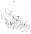
- the embodiment 1 shows the case where a hinge device H according to the present invention is applied to a collapsible type portable phone as shown in Fig. 1.
- the hinge device H according to the present invention is applied to a pivot mechanism in which a body portion provided with an operating portion 14 is used as a first member 1 and a joint portion provided with a display image field 15 is used as a second member 2 to make it possible to take the condition from the closed condition where the first member 1 and the second member 2 are coupled with each other to the open condition (busy condition) where the second member 2 is rotated to, for example, 120 degrees.
- a mounting hole 1a is provided in a proximal portion of the first member 1
- a mounting hole 2a is provided adjacent to and in communication with the mounting hole 1a also in a proximal portion of the second member 2
- the hinge device H according to the present invention constituted into an axial part is applied to the mounting holes 1a, 2a, respectively.
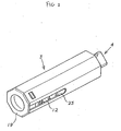
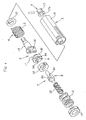
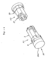
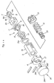
- a casing 16 is fixed to the body portion 1 (first member) as a joint portion constituting a part of a first joint member 3 having a rotation preventing shape through the above-described mounting hole 1a, and a member disposed in an exposed condition on one end side of this casing 16 is fixed as a mounting portion 17 constituting a part of a second joint member 4 through the mounting hole 2a to the joint portion 2 (second member) under the rotation prevented condition.
- This casing 16 has an octagonal shape in cross section as shown. This is adapted to attain the firm rotation preventing structure to the body portion 1. At the same time, the octagonal shape is adapted as a shape which allows the parts to be received effectively in its interior while providing the rotation preventing structure.
- An axial member 18 is provided at an inner hole 17a of the above-described mounting portion 17 under the rotation prevented condition to constitute the second joint member 4 provided with a cam portion 10 at its tip end portion.
- the axial member 18 relating to this second joint member 4 is adapted so that the cam portion 10 is disposed rotatably within the casing 16 relating to the first joint member 3.
- a closing member 19 is disposed on the other end side of the casing 16 relating to the first joint member 3, and furthermore, an engagement member 20 having a cam engagement portion 11 facing and engaging the cam portion 10 of the above-described second joint member 4 in a concave and convex manner is provided within the casing 16.
- This engagement member 20 is provided rotatably within the casing 16 and at the same time provided slidably in the engagement and disengagement direction within the casing 16.
- a coiled spring 12 for biasing in the engaging direction is provided as an engagement biasing member 12 within the casing 16 between the engagement member 20 having this cam engagement portion 11 and the closing member 19.
- a torque spring 13 is provided as a rotational biasing member 13 to the axial member 18 having the cam portion 10, the other end portion of the rotational biasing member 13 is coupled with a joint member 21 to be disposed under a rotation prevented condition within the casing 16, and accordingly, a biasing force for urging the rotational biasing member 16 to rotate the casing 16 in turn functions as a biasing force for rotating the axial member 18 (cam portion 10) by keeping the condition that the casing 16 is fixed.
- the cam engagement portion 11 is structured so that V-shaped concave portions are formed at diametrically 180 degree opposite positions, these concave portions are used as engagement portions with which the above-described cam portion 10 engages, and an apex portion (end face portion) of the cam portion 10 is brought into contact with an apex portion (end face portion) between the concave portions in the range of disengagement by the pressure force by the engagement biasing member 12.
- a frictional resistance increasing means is provided for increasing a frictional resistance between the apex portion of the cam portion 10 and the apex portion of the cam engagement portion 11, and when the apex portion of the cam portion 10 and the apex portion of the cam engagement portion 11 are brought into abutment with each other, the engagement is held at a stop position by the increase of the rotational resistance due to the frictional resistance increasing means and the pressure force of the engagement biasing member 12 so far as the members are not moved by hands even if the rotational biasing force of the rotational biasing member 13 is applied.
- the frictional resistance increasing means is structured so that the abutment area between the apex portion of the cam portion 10 and the apex portion of the cam engagement portion 11 is formed to be increased, whereby the frictional resistance between the apex portion of the cam portion 10 and the apex portion of the cam engagement portion 11 which are brought into pressing contact with each other by the biasing force of the engagement biasing member 12 is increased to realize the free stop.
- the free stop effect is generated for holding the joint portion 2 at any desired open angle position relative to the body portion 1.
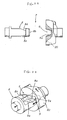
- the sliding convex strips 11b each having a length in the rotational direction of the cam engagement portion 11 are provided in the convex portion of the cam engagement portion 11 and sliding concave grooves 10b with which the sliding convex strips 11b are brought into abutment and engagement are provided in the above-described cam portion 10 whereby the abutment area between the apex portion 10a of the cam portion 10 and the apex portion 11a of the cam engagement portion 11 is increased and the frictional resistance between the apex portion 10a of the cam portion 10 and the apex portion 11a of the cam engagement portion 11 is enhanced.
- the above-described sliding convex strips 11b each having a length in the rotational direction of this apex portion 11a are provided substantially in the whole range of the apex portion 11a of the engagement cam 11 whereby substantially in the whole range where the above-described cam portion 10 is disengaged from the cam engagement portion 11 and the apex portion 10a of the cam portion 10 and the apex portion 11a of the cam engagement portion 11 are brought into contact with each other, the sliding convex strips 11b are in abutment and engagement with the sliding concave grooves 10b under the abutment condition.
- the sliding convex strips 11b are formed into arcuate shapes having a center at the center of the cam engagement portion 11 substantially in the middle in the diametrical direction of the apex portion 11a of the cam engagement portion 11 and are formed into convex strips each having a length in the rotational direction of the apex portion 11 a of the cam engagement portion 11.
- the sliding convex strips 11b and the sliding concave grooves 10b are formed into concave and convex shapes whose substantially whole surface portions are to be kept in abutment in the coupling engagement whereby the abutment areas of the apex portion 10a of the cam portion 10 and the apex portion 11a of the cam engagement portion 11 are increased to enhance the frictional resistance to make it possible to realize an extremely excellent free stop.
- the extremely excellent free stop operation may be exhibited substantially in the whole rotational range where the cam engagement portion 11 is disengaged from the cam portion 10 and the apex portion 11a of the cam engagement portion 11 and the apex portion 10a of the cam portion 10 are brought into abutment with each other.
- a rotation preventing structure portion 7 is provided for releaseably engaging with the above-described closing structure portion 5 and for preventing the closing structure portion 5 from rotating in the open direction by the opening structure portion 6.
- the retainer member 8 for engaging and disengaging the engagement concave portion 9 provided in the cam engagement portion 11 is provided in the casing 16 constituting the first joint member 3.
- the retainer member 8 is provided slidably away from the engagement direction under the rotation prevented condition through the joint member 23 and at the same time biased in the engagement direction by the engagement biasing member 22 as the coiled spring 22 for biasing in the engagement direction.
- the retainer member 8 is structured so that under the engagement condition with the cam engagement portion 11, the cooperative rotation between the cam portion 10 and the cam engagement portion 11 by the rotational biasing member 13 is prevented, at the same time, when this retainer member 8 is disengaged from the cam engagement portion 11, the cooperative rotation between the cam portion 10 and the cam engagement portion 11 is allowed by the rotational biasing member 13, and the engagement force of the retainer member 8 to this engagement portion 11 is set up to such an engagement force that the retainer member 8 is not disengaged from the cam engagement portion 11 by the biasing force of the rotational biasing member 13, and when the joint portion 2 is manually rotated in the opening direction relative to the body portion 1 exceeding the predetermined open angle position P2 against the closing rotational biasing force by the cam portion 10 and the cam engagement portion 11, the retainer member 8 may be disengaged from the cam engagement portion 11.
- taper surfaces 8a are formed at a tip end insertion portion to be inserted into the engagement concave portion 9, and by the angle setup of these taper surfaces 8a, when the joint portion 2 is manually rotated in the opening direction relative to the body portion 1 exceeding the predetermined open angle position P2 against the closing rotational biasing force by the cam portion 10 and the cam engagement portion 11, the engagement force is set up to such an engagement force that the retainer member 8 may be disengaged from the engagement concave portion 9.
- contact surfaces which are inner surfaces 9a of the engagement concave portion 9 and with which the taper surfaces 8a of the retainer member 8 are brought into contact are also formed in the taper surfaces 9a, the engagement force of the retainer member 8 relative to the engagement concave portion 9 may be selected suitably also by the angle setup of the taper surfaces 9a of this engagement concave portion 9.
- the present embodiment has the following operational effect.
- the closing rotational biasing effect is generated to automatically close the second member 2 to the coupled and closed position P1 relative to the first member 1.
- the open rotational biasing effect is generated to automatically open the second member 2 up to the predetermined open angle position P3 relative to the first member 1.
- the free stop effect is generated to hold the second member 2 in any desired open angle position relative to the first member 1.
- the joint portion 2 when the joint portion 2 is manually rotated in the open direction exceeding the predetermined open angle position P2 relative to the body portion 1, the joint portion 2 is automatically opened to the predetermined open angle position P3.
- the joint portion 2 kept under the open condition to this predetermined open angle position P3 is rotated in the closing direction, in the rotational range A2 up to the predetermined open angle position P2, the joint portion 2 is always kept under the slant condition relative to the body portion 1.
- the joint portion 1 Exceeding the predetermined open angle position P2, the joint portion 1 is automatically closed to the coupled and closed position P1.
- the closing rotational biasing force for urging the joint portion 2 in the closing direction relative to the body portion 1 is generated.
- the open rotational biasing force for urging the joint portion 2 in the open direction relative to the body portion 1 is generated.
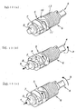
- the cam portion 10 is rotated while being disengaged from the cam engagement portion 11.
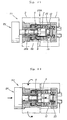
- the cam engagement portion 11 and the retainer member 8 are retracted in the direction indicated by b in Fig. 14(b) against the engagement biasing member 12 (and the engagement biasing member 22) so that the cam portion 10 and the cam engagement portion 11 are completely disengaged from each other (see Fig. 14(b)).
- the second joint member 4 is further rotated in the direction indicated by the arrow d in Fig.
- the joint portion 2 in use, for example, when the finger of the hand holding the phone is inserted between the joint portion 2 and the body portion 1 so that the joint portion 2 is rotated in the open direction relative to the body portion 1, the joint portion 2 is automatically opened due to the open rotational biasing operation. This is extremely useful because the opening operation of the joint portion 2 may readily and quickly be performed.
- the free stop effect is generated for holding the second member 2 relative to the first member 1 at any desired angle portion. Accordingly, it is possible to use the phone while the joint portion 2 is stopped at a desired angle at which the phone is easy to use, which is more useful.
- the embodiment 1 shows the case where a hinge device H according to the present invention is applied to a collapsible type portable phone as shown in Fig. 17.
- the hinge device H according to the present invention is applied to a pivot mechanism in which a body portion provided with an operating portion 14 is used as a first member 1 and a joint portion provided with a display image field 15 is used as a second member 2 to make it possible to take the condition from the closed condition where the first member 1 and the second member 2 are coupled with each other to the open condition (busy condition) where the second member 2 is rotated to, for example, 120 degrees.
- the present embodiment is composed of a first hinge body H1 provided in a first pivot portion 25A provided at any one position of right and left positions of a pivot joint portion 25 between the first member 1 and the second member 2 and a second hinge member H2 provided in a second pivot portion 25B provided in the other position.
- a closing structure portion 5 is provided in the first hinge member H1 for generating a closing rotational biasing effect for automatically closing the second member 2 to the coupled and closed position P1 relative to the first member 1 when the second member 2 kept under the coupled and closed condition relative to the first member 1 is opened, in a rotational range A1 from the coupled and closed position P1 to a predetermined open angle position P2 rotated in the open direction.
- an open structure portion 6 is provided in the second hinge member H2 for generating the open rotational biasing effect for automatically opening the second member 2 to the predetermined open angle position P3 relative to the first member 1 by urging this closing structure portion 5 in the rotational direction.
- a rotation preventing structure portion 7 is provided for releaseably engaging with the closing structure portion 5 and for preventing the rotation of the closing structure portion 5 by the opening structure portion 6.
- a depression button portion 26 for releasing the retention of the rotation preventing structure portion 7 to this closing structure portion 5 is provided in the rotation preventing structure portion 7.
- mounting holes 1b, 1c are provided in right and left portions of a proximal end of the first member 1, respectively.
- mounting holes 2b, 2c adjacent to and in communication with the mounting holes 1b, 1c are provided in right and left portions of a proximal end of the second member 2, respectively.
- a hinge device H first hinge member H1 and second hinge member H2 according to the present invention is applied as axial parts to the first pivot portion 25A and the second pivot portion 25B constituted by these respective mounting holes.
- the first hinge member H1 will be described.
- a casing 16 as a joint portion for constituting a part of a first joint member 3 having a rotational preventing shape through the above-described mounting hole 1b is fixed to the body portion 1 (first member).
- a member disposed at one end side of this casing 16 in the exposed condition as a mounting portion 17 constituting a second joint member 4 is fixed to the joint portion 2 (second member) through the mounting hole 2b in a rotation prevented manner.
- This casing 16 has an octagonal shape in cross section as shown. This is adapted to attain the firm rotation preventing structure to the body portion 1. At the same time, the octagonal shape is adapted as a shape which allows the parts to be received effectively in its interior while providing the rotation preventing structure.
- An axial member 18 is provided at an inner hole 17a of the above-described mounting portion 17 under the rotation prevented condition to constitute the second joint member 4 provided with a cam portion 10.
- the axial member 18 relating to this second joint member 4 is adapted so that the cam portion 10 is disposed rotatably within the casing 16 relating to the first joint member 3.
- a closing member 19 is disposed on the other end side of the casing 16 relating to the first joint member 3, and furthermore, an engagement member 20 having a cam engagement portion 11 facing and engaging the cam portion 10 of the above-described second joint member 4 in a concave and convex manner is provided within the casing 16.
- This engagement member 20 is provided rotatably within the casing 16 and at the same time provided slidably in the disengagement direction within the casing 16.
- a coiled spring 12 for biasing in the engaging direction is provided as an engagement biasing member 12 within the casing 16 between the engagement member 20 having this cam engagement portion 11 and the closing member 19.
- a tip end of this coiled spring 12 is coupled with a joint member 23 to be described later and the cam engagement portion 11 is biased in the engagement direction through this joint member 23.
- the cam portion 10 and the cam engagement portion 11 are adapted to be rotated together under the engagement condition without disengagement therebetween.
- the cam engagement portion 11 is structured so that V-shaped concave portions are formed at diametrically 180 degree opposite positions, these concave portions are used as engagement portions with which the above-described cam portion 10 engages, and an apex portion (end face portion) of the cam portion 10 is brought into contact with an apex portion (end face portion) between the concave portions in the range of disengagement by the pressure force by the engagement biasing member 12.
- a frictional resistance increasing means is provided for increasing a frictional resistance between the apex portion of the cam portion 10 and the apex portion of the cam engagement portion 11, and when the apex portion of the cam portion 10 and the apex portion of the cam engagement portion 11 are brought into abutment with each other, the engagement is held at a stop position by the increase of the rotational resistance due to the frictional resistance increasing means and the pressure force of the engagement biasing member 12 so far as the members are not moved by hands even if the rotational biasing force of the rotational biasing member 13 to be described later is applied.
- the frictional resistance increasing means is structured so that the abutment area between the apex portion of the cam portion 10 and the apex portion of the cam engagement portion 11 is formed to be increased, whereby the frictional resistance between the apex portion of the cam portion 10 and the apex portion of the cam engagement portion 11 which are brought into pressing contact with each other by the biasing force of the engagement biasing member 12 is increased to realize the free stop.
- the free stop effect is generated for holding the joint portion 2 at any desired open angle position relative to the body portion 1.
- the sliding convex strips 11b each having a length in the rotational direction of the cam engagement portion 11 are provided in the convex portion of the cam engagement portion 11 and sliding concave grooves 10b with which the sliding convex strips 11b are brought into abutment and engagement are provided in the above-described cam portion 10 whereby the abutment area between the apex portion 10a of the cam portion 10 and the apex portion 11a of the cam engagement portion 11 is increased and the frictional resistance between the apex portion 10a of the cam portion 10 and the apex portion 11a of the cam engagement portion 11 is enhanced.
- the above-described sliding convex strips 11b each having a length in the rotational direction of this apex portion 11a are provided substantially in the whole range of the apex portion 11a of the engagement cam 11 whereby substantially in the whole range where the above-described cam portion 10 is disengaged from the cam engagement portion 11 and the apex portion 10a of the cam portion 10 and the apex portion 11a of the cam engagement portion 11 are brought into contact with each other, the sliding convex strips 11b are in abutment and engagement with the sliding concave grooves 10b under the abutment condition.
- the sliding convex strips 11b are formed into arcuate shapes having a center at the center of the cam engagement portion 11 substantially in the middle in the diametrical direction of the apex portion 11a of the cam engagement portion 11 and are formed into convex strips each having a length in the rotational direction of the apex portion 11a of the cam engagement portion 11.
- the sliding convex strips 11b and the sliding concave grooves 10b are formed into concave and convex shapes whose substantially whole surface portions are to be kept in abutment in the coupling engagement whereby the abutment areas of the apex portion 10a of the cam portion 10 and the apex portion 11a of the cam engagement portion 11 are increased to enhance the frictional resistance to make it possible to realize an extremely excellent free stop.
- the extremely excellent free stop operation may be exhibited substantially in the whole rotational range where the cam engagement portion 11 is disengaged from the cam portion 10 and the apex portion 11a of the cam engagement portion 11 and the apex portion 10a of the cam portion 10 are brought into abutment with each other.
- a rotation preventing structure portion 7 is provided for releaseably engaging with the above-described closing structure portion 5 and for preventing the closing structure portion 5 from rotating in the open direction by the opening structure portion 6 provided in the second hinge member H2 to be described later.
- the retainer member 8 for engaging and disengaging the engagement concave portion 9 provided in the cam engagement portion 11 is provided in the casing 16 constituting the first joint member 3.
- the retainer member 8 is provided slidably away from the engagement direction under the rotation prevented condition within the casing 16 through the joint member 23 and at the same time biased in the engagement direction by the engagement biasing member 22 as the coiled spring 22 for biasing in the engagement direction.
- the retainer member 8 is structured so that under the engagement condition with the cam engagement portion 11, the cooperative rotation between the cam portion 10 and the cam engagement portion 11 by the rotational biasing member 13 is prevented, at the same time, when this retainer member 8 is disengaged from the cam engagement portion 11, the cooperative rotation between the cam portion 10 and the cam engagement portion 11 is allowed by the rotational biasing member 13, and the engagement force of the retainer member 8 to this engagement portion 11 is set up to such an engagement force that the retainer member 8 is not disengaged from the cam engagement portion 11 by the biasing force of the rotational biasing member 13, and when the joint portion 2 is manually rotated in the opening direction relative to the body portion 1 exceeding the predetermined open angle position P2 against the closing rotational biasing force by the cam portion 10 and the cam engagement portion 11, the retainer member 8 may be disengaged from the cam engagement portion 11.
- taper surfaces 8a are formed at a tip end insertion portion to be inserted into the engagement concave portion 9, and by the angle setup of these taper surfaces 8a, when the joint portion 2 is manually rotated in the opening direction relative to the body portion 1 exceeding the predetermined open angle position P2 against the closing rotational biasing force by the cam portion 10 and the cam engagement portion 11, the engagement force is set up to such an engagement force that the retainer member 8 is slidingly moved against the engagement bias of the engagement biasing member 22 so that the retainer member 8 may be disengaged from the engagement concave portion 9.
- contact surfaces which are inner surfaces 9a of the engagement concave portion 9 and with which the taper surfaces 8a of the retainer member 8 are brought into contact are also formed in the taper surfaces 9a, the engagement force of the retainer member 8 relative to the engagement concave portion 9 may be selected suitably also by the angle setup of the taper surfaces 9a of this engagement concave portion 9.
- this rotation preventing structure portion 7 is provided with the depression button portion 26 for releasing the retention of the retainer member 8 to the above-described closing structure portion 5.
- this depression button portion 26 is structured so that an axial portion 26b projects from an inner center position of a depression portion 26a having a circular shape in frontal view. This axial portion 26b is disposed to pass through an axial hole 18a provided in the axial member 18 relating to the second joint member 4 in a pull-apart preventing manner.
- the depression button portion 26 is provided with the axial portion 26b slidable within the axial hole 18a of the axial member 18.
- a tip end portion 26b' of the axial portion 26b is adapted to come into contact with a tip end face 8b of the above-described retainer member 8.
- the retainer member 8 is slidingly moved against the engagement bias of the engagement biasing member 22 so that the retention to the engagement concave portion 9 provided in the above-described cam engagement portion 11 is released.
- the second hinge member H2 will be described.
- a casing 28 as a joint portion constituting a part of a third joint member 27 having a rotation preventing shape through the above-described mounting hole 1c is fixed to the body portion 1 (first member).
- a member to be disposed in an exposed condition at one end side of this casing 28 is fixed in a rotation prevented manner to the joint portion 2 (second member) through the mounting hole 2c as a mounting portion 30 constituting a part of a fourth joint member 29.
- This casing 28 has an octagonal shape in cross section as shown. This is adapted to attain the firm rotation preventing structure to the body portion 1.
- the octagonal shape is adapted as a shape which allows the parts to be received effectively in its interior while providing the rotation preventing structure.
- a joint member 31 to be coupled with a torque spring 13 as the rotational biasing member 13 is provided in a rotation prevented condition at a tip end portion to the inner hole 30a of the above-described mounting portion 30.
- the other end portion of this rotational biasing member 13 is coupled with a joint member 32 disposed in a rotation prevented condition at the other end portion of the casing 28. Accordingly, the biasing force of the rotational biasing member 13 for rotating the casing 28 functions as a biasing force for rotating the fourth joint member 29 with the casing 28 being fixed.
- the present embodiment has the following operational effect.
- the closing rotational biasing effect is generated to automatically close the second member 2 to the coupled and closed position P1 relative to the first member 1.
- the open rotational biasing effect is generated to automatically open the second member 2 up to the predetermined open angle position P3 relative to the first member 1.
- the free stop effect is generated to hold the second member 2 in any desired open angle position relative to the first member 1.
- the joint portion 2 when the joint portion 2 is manually rotated in the open direction exceeding the predetermined open angle position P2 relative to the body portion 1, or when the depression button portion 26 is operated to be depressed, the joint portion is automatically opened to the predetermined open angle position P3.
- the joint portion 2 kept under the opened condition to this predetermined open angle position P3 is rotated in the closing direction, in the rotational range A2 up to the predetermined open angle position P2, the joint portion 2 is always kept under the slanted condition relative to the body portion 1.
- the joint portion 1 is automatically closed to the coupled and closed position P1.
- the cam portion 10 and the cam engagement portion 11 are cooperatively rotated in a somewhat disengaged manner while they are to be disengaged from each other.
- the retainer member 8 is completely disengaged from the engagement concave portion 9 of the cam engagement portion 11 while being retracted. Thereafter, the retainer member 8 biased by the engagement biasing member 22 is advanced again and fitted and engaged with the engagement concave portion 9.
- the closing rotational biasing force for urging the joint portion 2 in the closing direction relative to the body portion 1 is generated.
- the open rotational biasing force for urging the joint portion 2 in the open direction relative to the body portion 1 is generated.
- the cam portion 10 is rotated while being disengaged from the cam engagement portion 11.
- the cam engagement portion 11 and the retainer member 8 are retracted against the engagement biasing member 12 (and the engagement biasing member 22).
- the free stop effect is generated due to the frictional resistance between the apex portion 10a of the cam portion 10 and the apex portion of the cam engagement portion 11.
- the cam portion 10 and the cam engagement portion 11 are biased by the engagement biasing member 12 and are in dropping engagement with each other to thereby generate the closing biasing power whereby the joint portion 2 is completely brought into closed condition.
- the joint portion 2 in use, for example, when the finger of the hand holding the phone is inserted between the joint portion 2 and the body portion 1 so that the joint portion 2 is rotated in the open direction relative to the body portion 1, or the depression button portion 26 is operated to be depressed, the joint portion 2 is automatically opened due to the open rotational biasing operation. This is extremely useful because the opening operation of the joint portion 2 may readily and quickly be performed.
- the free stop effect is generated for holding the second member 2 relative to the first member 1 at any desired angle portion. Accordingly, it is possible to use the phone while the joint portion 2 is stopped at a desired angle at which the phone is easy to use, which is more useful.
- the hinge device H disposed to the pivotal joint portion 25 between the body portion 1 and the joint portion 2 is the hinge structure (double hinge structure) composed of the first hinge member H1 provided with the closing structure portion 5 and the rotation preventing structure portion 7 and the second hinge member H2 provided with the opening structure portion 6. Therefore, the pivotal joint portion 25 between the body portion 1 and the joint portion 2 for providing this hinge device H may be divided on the right and left sides and each pivotal portion (first pivotal portion 25A and second pivotal portion 25B) may be made small in size.
- this vacant space S serves to keep a sufficient space suitable for arranging wirings for electrically connecting electronic parts to be disposed within the joint portion 2 and electronic parts to be disposed within the body portion 1. Such effect and the like may be ensured.
- the present invention is not limited to or by the embodiments 1, 2 but the specific structure of each component may be designed as desired.
Landscapes
- Engineering & Computer Science (AREA)
- Signal Processing (AREA)
- Human Computer Interaction (AREA)
- General Engineering & Computer Science (AREA)
- Computer Networks & Wireless Communication (AREA)
- Mechanical Engineering (AREA)
- Pivots And Pivotal Connections (AREA)
Applications Claiming Priority (5)
| Application Number | Priority Date | Filing Date | Title |
|---|---|---|---|
| JP2003024067A JP3910542B2 (ja) | 2003-01-31 | 2003-01-31 | ヒンジ装置並びにヒンジ装置を用いた電子機器 |
| JP2003024067 | 2003-01-31 | ||
| JP2003209785A JP3910566B2 (ja) | 2003-08-29 | 2003-08-29 | ヒンジ装置並びにヒンジ装置を用いた電子機器 |
| JP2003209785 | 2003-08-29 | ||
| PCT/JP2003/016002 WO2004067976A1 (fr) | 2003-01-31 | 2003-12-12 | Dispositif de charniere et dispositif electronique utilisant ce dispositif de charniere |
Publications (2)
| Publication Number | Publication Date |
|---|---|
| EP1589239A1 true EP1589239A1 (fr) | 2005-10-26 |
| EP1589239A4 EP1589239A4 (fr) | 2008-04-30 |
Family
ID=32828926
Family Applications (1)
| Application Number | Title | Priority Date | Filing Date |
|---|---|---|---|
| EP03780746A Withdrawn EP1589239A4 (fr) | 2003-01-31 | 2003-12-12 | Dispositif de charniere et dispositif electronique utilisant ce dispositif de charniere |
Country Status (4)
| Country | Link |
|---|---|
| US (2) | US7434296B2 (fr) |
| EP (1) | EP1589239A4 (fr) |
| KR (1) | KR100978709B1 (fr) |
| WO (1) | WO2004067976A1 (fr) |
Cited By (1)
| Publication number | Priority date | Publication date | Assignee | Title |
|---|---|---|---|---|
| CN101076042B (zh) * | 2006-05-17 | 2010-06-23 | 加藤电机株式会社 | 铰链装置以及便携式设备 |
Families Citing this family (36)
| Publication number | Priority date | Publication date | Assignee | Title |
|---|---|---|---|---|
| US20100134964A1 (en) * | 2004-03-08 | 2010-06-03 | Originatic Llc | Electronic Device |
| WO2006012515A2 (fr) * | 2004-07-23 | 2006-02-02 | Southco, Inc. | Ensemble articulation a mouvement bidirectionnel |
| US20060226750A1 (en) * | 2005-04-08 | 2006-10-12 | Lee Jeong Y | Refrigerator having home bar |
| CN1870873A (zh) * | 2005-05-28 | 2006-11-29 | 深圳富泰宏精密工业有限公司 | 铰链装置及应用该铰链装置的便携式电子装置 |
| KR100630138B1 (ko) * | 2005-08-17 | 2006-10-02 | 삼성전자주식회사 | 휴대용 단말기의 힌지 장치 |
| KR100701500B1 (ko) * | 2006-06-16 | 2007-03-29 | 주식회사 엠투시스 | 휴대 단말기용 개폐장치 |
| CN100501177C (zh) * | 2006-06-23 | 2009-06-17 | 鸿富锦精密工业(深圳)有限公司 | 铰链结构及应用该铰链结构的折叠式电子装置 |
| CN101484711B (zh) * | 2006-06-30 | 2011-06-08 | 株式会社思特百利 | 枢接装置及使用枢接装置的电子机器 |
| KR100849318B1 (ko) * | 2006-08-22 | 2008-07-29 | 삼성전자주식회사 | 힌지 장치 및 그를 구비하는 휴대용 단말기 |
| CN101140008B (zh) * | 2006-09-05 | 2012-11-21 | 鸿富锦精密工业(深圳)有限公司 | 铰链结构 |
| KR100777226B1 (ko) * | 2006-09-20 | 2007-11-19 | 주식회사 엠투시스 | 휴대폰 단말기용 힌지모듈 |
| WO2008035895A1 (fr) * | 2006-09-18 | 2008-03-27 | Laird Technologies Map Co., Ltd. | Charnière de terminal portable |
| CN101336074B (zh) * | 2007-06-29 | 2012-08-22 | 深圳富泰宏精密工业有限公司 | 装配装置及应用其装配配件的便携式电子装置 |
| CN101338783B (zh) * | 2007-07-04 | 2011-03-30 | 深圳富泰宏精密工业有限公司 | 铰链结构及应用该铰链结构的便携式电子装置 |
| KR100857707B1 (ko) * | 2007-10-15 | 2008-09-08 | 한일이화주식회사 | 차량의 커버링 쉘프 개폐체 |
| KR100912611B1 (ko) * | 2007-11-02 | 2009-08-17 | (주)엘티엠에이피 | 휴대폰 자동 힌지모듈 |
| CN101469738B (zh) * | 2007-12-29 | 2012-07-25 | 深圳富泰宏精密工业有限公司 | 铰链机构及应用该铰链机构的便携式电子装置 |
| US20090188080A1 (en) * | 2008-01-29 | 2009-07-30 | Cheng Uei Precision Industry Co., Ltd. | Hinge |
| US7814620B2 (en) * | 2008-01-29 | 2010-10-19 | Cheng Uei Precision Industry Co., Ltd. | Hinge |
| US20090320239A1 (en) * | 2008-06-26 | 2009-12-31 | Nokia Corporation | Apparatus for fold hinge assemblies for electronic devices and associated methods |
| CN101660569A (zh) * | 2008-08-29 | 2010-03-03 | 深圳富泰宏精密工业有限公司 | 铰链机构及应用该铰链机构的便携式电子装置 |
| CN101660568A (zh) * | 2008-08-29 | 2010-03-03 | 深圳富泰宏精密工业有限公司 | 铰链机构及应用该铰链机构的便携式电子装置 |
| US8224405B2 (en) * | 2008-12-18 | 2012-07-17 | Motorola Mobility, Inc. | Implementation of friction hinge with a range of motion and detent separation greater than 180 degrees |
| CN101782104B (zh) * | 2009-01-16 | 2013-04-24 | 深圳富泰宏精密工业有限公司 | 套筒及应用该套筒的铰链结构 |
| CN102032265B (zh) * | 2009-09-24 | 2013-01-09 | 深圳富泰宏精密工业有限公司 | 铰链结构及应用该铰链结构的便携式电子装置 |
| CN102207128A (zh) * | 2010-03-30 | 2011-10-05 | 深圳富泰宏精密工业有限公司 | 套筒及应用该套筒的铰链结构 |
| KR101039522B1 (ko) * | 2010-04-05 | 2011-06-08 | 케이. 에이. 이 (주) | 이동통신 단말기용 힌지조립체 |
| CN102221041B (zh) * | 2010-04-19 | 2013-04-24 | 深圳富泰宏精密工业有限公司 | 铰链结构及应用该铰链结构的便携式电子装置 |
| US8424160B2 (en) * | 2010-08-11 | 2013-04-23 | E-Lead Electronics Co., Ltd. | Asymmetrical resistant hinge set |
| CN102454692B (zh) * | 2010-10-21 | 2015-03-18 | 赛恩倍吉科技顾问(深圳)有限公司 | 铰链结构及应用该铰链结构的便携式电子装置 |
| CN102454693B (zh) * | 2010-10-29 | 2013-12-25 | 深圳富泰宏精密工业有限公司 | 铰链结构及应用该铰链结构的便携式电子装置 |
| CN102486203B (zh) * | 2010-12-03 | 2014-04-16 | 深圳富泰宏精密工业有限公司 | 铰链结构及应用该铰链结构的便携式电子装置 |
| CN102562781B (zh) * | 2010-12-09 | 2014-03-26 | 深圳富泰宏精密工业有限公司 | 铰链结构及应用该铰链结构的便携式电子装置 |
| US8745820B2 (en) * | 2011-09-30 | 2014-06-10 | Itt Manufacturing Enterprises Llc | Rotary hinge with adjustable damping assembly |
| TWI522780B (zh) * | 2013-11-06 | 2016-02-21 | 宏碁股份有限公司 | 可攜式電子裝置 |
| JP6752363B2 (ja) * | 2016-09-30 | 2020-09-09 | 杭州安費諾飛鳳通信部品有限公司 | 回転部品のヒンジおよびモバイル端末 |
Family Cites Families (21)
| Publication number | Priority date | Publication date | Assignee | Title |
|---|---|---|---|---|
| US5649309A (en) | 1995-05-18 | 1997-07-15 | Motorola, Inc. | Wireless communication device having an axially aligned cover release mechanism |
| US6348567B1 (en) * | 1995-12-06 | 2002-02-19 | Cv Molecular Therapeutics Inc. | Peptides and their use to ameliorate cell death |
| JP2001355371A (ja) * | 2000-06-14 | 2001-12-26 | Kato Electrical Mach Co Ltd | 小型ヒンジ装置 |
| US6678539B1 (en) * | 2001-01-22 | 2004-01-13 | Lu Sheng-Nan | Mobile phone cover hinge |
| JP3544949B2 (ja) * | 2001-02-05 | 2004-07-21 | 株式会社ストロベリーコーポレーション | ヒンジ装置並びにヒンジ装置を用いた携帯式電子機器 |
| TWI241822B (en) * | 2001-03-22 | 2005-10-11 | Nifco Inc | Rotary actuator for hinge |
| TW507979U (en) * | 2001-04-04 | 2002-10-21 | Benq Corp | magnetic hinge apparatus |
| JP4357136B2 (ja) | 2001-04-19 | 2009-11-04 | 株式会社ニフコ | ヒンジ装置 |
| KR100665709B1 (ko) * | 2001-04-26 | 2007-01-10 | 피닉스코리아 주식회사 | 힌지장치 |
| JP3656041B2 (ja) * | 2001-07-06 | 2005-06-02 | 株式会社ストロベリーコーポレーション | ヒンジ装置並びにヒンジ装置を用いた電子機器 |
| TW482229U (en) * | 2001-07-17 | 2002-04-01 | Hinge Basestrong Co Ltd | Rotating axle structure with lift and close function |
| JP3906702B2 (ja) * | 2002-02-12 | 2007-04-18 | 松下電器産業株式会社 | 開閉装置及びこれを用いた電子機器 |
| KR100530618B1 (ko) | 2002-03-18 | 2005-11-23 | 이영화 | 힌지 장치 |
| JP2004044665A (ja) * | 2002-07-10 | 2004-02-12 | Nippon Koki Co Ltd | 携帯電子機器 |
| JP2004060697A (ja) * | 2002-07-25 | 2004-02-26 | Ykm:Kk | 多段階展開ヒンジ装置 |
| JP2004270714A (ja) * | 2003-03-05 | 2004-09-30 | Nifco Inc | ヒンジユニット及びこのヒンジユニットを用いたヒンジ構造 |
| US7895710B2 (en) * | 2003-07-23 | 2011-03-01 | Fujitsu Limited | Hinge device |
| TWM255628U (en) * | 2003-09-05 | 2005-01-11 | Fih Co Ltd | Hinge assembly |
| JP2005163885A (ja) * | 2003-12-02 | 2005-06-23 | Matsushita Electric Ind Co Ltd | 開閉装置 |
| KR100539919B1 (ko) * | 2003-12-30 | 2005-12-28 | 삼성전자주식회사 | 힌지 장치 및 그를 구비하는 휴대용 단말기 |
| JP4325540B2 (ja) * | 2004-11-12 | 2009-09-02 | パナソニック株式会社 | 開閉装置 |
-
2003
- 2003-12-12 KR KR1020057002153A patent/KR100978709B1/ko not_active Expired - Fee Related
- 2003-12-12 WO PCT/JP2003/016002 patent/WO2004067976A1/fr not_active Ceased
- 2003-12-12 EP EP03780746A patent/EP1589239A4/fr not_active Withdrawn
- 2003-12-12 US US10/536,837 patent/US7434296B2/en not_active Expired - Fee Related
-
2007
- 2007-10-31 US US11/930,646 patent/US7653968B2/en not_active Expired - Fee Related
Cited By (1)
| Publication number | Priority date | Publication date | Assignee | Title |
|---|---|---|---|---|
| CN101076042B (zh) * | 2006-05-17 | 2010-06-23 | 加藤电机株式会社 | 铰链装置以及便携式设备 |
Also Published As
| Publication number | Publication date |
|---|---|
| US7653968B2 (en) | 2010-02-02 |
| US7434296B2 (en) | 2008-10-14 |
| US20080201900A1 (en) | 2008-08-28 |
| KR100978709B1 (ko) | 2010-08-30 |
| WO2004067976A1 (fr) | 2004-08-12 |
| US20060005353A1 (en) | 2006-01-12 |
| EP1589239A4 (fr) | 2008-04-30 |
| KR20050088068A (ko) | 2005-09-01 |
Similar Documents
| Publication | Publication Date | Title |
|---|---|---|
| US7653968B2 (en) | Hinge device and electronic instrument using the hinge device | |
| US6708046B1 (en) | Folding portable telephone having enhanced operability | |
| US6148480A (en) | Hinge construction with a snap-open, snap-shut feel, for a folding mobile phone handset | |
| EP1093274B1 (fr) | Structure de charnière pour un téléphone portable et pliable | |
| CN101889428B (zh) | 蜂窝式电话的自动铰接模块 | |
| JP4653212B2 (ja) | 折りたたみ型携帯電話機 | |
| JP3459606B2 (ja) | 折り畳み式携帯電話機 | |
| JP3392801B2 (ja) | 折り畳み式携帯電話機 | |
| US20100050384A1 (en) | Automatically opening hinge assembly for portable electronic devices | |
| US20060188092A1 (en) | Mobile terminal with a hinge, a method of operating the mobile terminal and a hinge | |
| US20050055805A1 (en) | Hinge assembly with integrating shaft | |
| JP3544949B2 (ja) | ヒンジ装置並びにヒンジ装置を用いた携帯式電子機器 | |
| JPWO2006087912A1 (ja) | 折畳式携帯機器及びヒンジ装置 | |
| JP3668450B2 (ja) | ヒンジ装置並びにヒンジ装置を用いた電子機器 | |
| JP2004060697A (ja) | 多段階展開ヒンジ装置 | |
| JP3910542B2 (ja) | ヒンジ装置並びにヒンジ装置を用いた電子機器 | |
| JP4372029B2 (ja) | 枢着装置並びに枢着装置を用いた電子機器 | |
| JP2006220198A (ja) | ヒンジ装置並びにヒンジ装置を用いた電子機器 | |
| JP3924195B2 (ja) | ヒンジ装置並びにヒンジ装置を用いた電子機器 | |
| JP2005147344A (ja) | ヒンジ装置 | |
| KR100537992B1 (ko) | 휴대용 무선단말기의 힌지 모듈 | |
| KR100664175B1 (ko) | 이동단말기의 힌지 토오크 조절장치 | |
| JP2009047258A (ja) | ヒンジ機構および携帯端末 | |
| JP2003113833A (ja) | ヒンジ装置並びにヒンジ装置を用いた電子機器 | |
| JP2004183813A (ja) | ヒンジ装置並びにヒンジ装置を用いた電子機器 |
Legal Events
| Date | Code | Title | Description |
|---|---|---|---|
| PUAI | Public reference made under article 153(3) epc to a published international application that has entered the european phase |
Free format text: ORIGINAL CODE: 0009012 |
|
| 17P | Request for examination filed |
Effective date: 20050316 |
|
| AK | Designated contracting states |
Kind code of ref document: A1 Designated state(s): AT BE BG CH CY CZ DE DK EE ES FI FR GB GR HU IE IT LI LU MC NL PT RO SE SI SK TR |
|
| RAP1 | Party data changed (applicant data changed or rights of an application transferred) |
Owner name: KABUSHIKI KAISHA STRAWBERRY CORPORATION |
|
| RBV | Designated contracting states (corrected) |
Designated state(s): FI GB |
|
| REG | Reference to a national code |
Ref country code: DE Ref legal event code: 8566 |
|
| A4 | Supplementary search report drawn up and despatched |
Effective date: 20080402 |
|
| 17Q | First examination report despatched |
Effective date: 20101112 |
|
| STAA | Information on the status of an ep patent application or granted ep patent |
Free format text: STATUS: THE APPLICATION IS DEEMED TO BE WITHDRAWN |
|
| 18D | Application deemed to be withdrawn |
Effective date: 20110524 |