FIELD OF THE INVENTION
The present invention relates to a hinge device and an electronic
instrument using the hinge device.
BACKGROUND ART
For example, a portable phone as a typical example of a portable
electronic instrument is of collapsible type in which a portable phone
body (a body portion and a joint portion) is collapsible.
This collapsible type is popular in aspects of preventing a switch
from malfunctioning, making the phone compact when the phone is
collapsed (to keep a display area sufficient), a variety of designs and the
like.
Accordingly, while ones' eyes are kept on this collapsible type
portable phone more and more, there are demands to provide a more
useful phone.
The present applicant has made further experiments and studies
repeatedly with respect to the above-described hinge device and has
developed a novel hinge device and an electronic instrument using the
hinge device which is more valuable as a commercial product.
DISCLOSURE OF THE INVENTION
The essence of the present invention will be described with reference
to the accompanying drawings.
The present invention relates to a hinge device for pivoting a first
member 1 and a second member 2 to be rotatably opened and closed,
characterized in that when the second member 2 kept under a coupled and
closed condition is opened to the first member 1, in a rotational range A1
from the coupled and closed position P1 to a predetermined open angle
position P2 rotated in an open direction, a closing rotational biasing
effect is generated for automatically closing the second member 2 to the
coupled and closed position P1 relative to the first member 1, and when
the second member 2 is manually rotated in the open direction exceeding
the predetermined open angle position P2 to the first member 1, an open
rotational biasing effect is generated for automatically opening the
second member 2 to a predetermined open angle position P3 relative to
the first member 1.
Also, the invention relates to a hinge device for pivoting a first
member 1 and a second member 2 to be rotatably opened and closed,
characterized in that when the second member 2 kept under a coupled and
closed condition is opened to the first member 1, in a rotational range A1
from the coupled and closed position P1 to a predetermined open angle
position P2 rotated in an open direction, a closing rotational biasing
effect is generated for automatically closing the second member 2 to the
coupled and closed position P1 relative to the first member 1, when the
second member 2 is manually rotated in the open direction exceeding the
predetermined open angle position P2 to the first member 1, an open
rotational biasing effect is generated for automatically opening the
second member 2 to a predetermined open angle position P3 relative to
the first member 1, and in a rotational range A2 to the predetermined
open angle position P2 rotated in the closing direction from a position
where the second member 2 is opened to the first member 1, a free stop
effect is generated for holding the second member 2 at any desired open
angle position relative to the first member 1.
The invention relates to a hinge device for pivoting a first member 1
and a second member 2 to be rotatably opened and closed, characterized
by comprising a closing structure portion 5 for generating a close
rotational biasing effect for automatically closing the second member 2
to the coupled and closed position P1 relative to the first member 1 in a
rotational range A1 from the coupled and closed position P1 to a
predetermined open angle position P2 rotated in an open direction when
the second member 2 kept under a coupled and closed condition is
opened to the first member 1, an opening structure portion 6 for
generating an open rotational biasing effect for automatically opening
the second member 2 to a predetermined open angle position P3 relative
to the first member 1, by biasing said closing structure portion in the
rotational direction when the second member 2 is manually rotated in the
open direction exceeding the predetermined open angle position P2 to the
first member 1, and a rotation preventing structure portion 7 for
releaseably retaining at said closing structure portion 5 and preventing
the rotation of the closing structure portion 6 in the open direction by
said opening structure portion 6, wherein a retention force of the rotation
preventing structure portion 7 to the closing structure portion 5 is set up
so that the rotation preventing structure portion 7 is not disengaged from
the closing structure portion 5 by the opening rotational biasing force of
said opening structure portion 6 and the rotation preventing structure
portion 7 may be disengaged from the closing structure portion 5 when
the second member 2 is manually rotated in the open direction exceeding
the predetermined open angle position P2 against the closing rotational
biasing force by said closing structure portion 5 relative to said first
member 1.
Also, the invention relates to the hinge device according to claim 3,
characterized in that a depression button portion 26 for releasing the
retention of the rotation preventing structure portion 7 to said closing
structure portion 5 is provided in said rotation preventing structure
portion 7.
Also, the invention relates to a hinge device for pivoting a first
member 1 and a second member 2 to be rotatably opened and closed,
characterized by comprising a closing structure portion 5 for generating
a close rotational basing effect for automatically closing the second
member 2 to the coupled and closed position P1 relative to the first
member 1 in a rotational range A1 from the coupled and closed position
P1 to a predetermined open angle position P2 rotated in an open direction
when the second member 2 kept under a coupled and closed condition is
opened to the first member 1, an opening structure portion 6 for
generating an open rotational biasing effect for automatically opening
the second member 2 to a predetermined open angle position P3 relative
to the first member 1, by biasing said closing structure portion 5 in the
rotational direction when the second member 2 is manually rotated in the
open direction exceeding the predetermined open angle position P2 to the
first member 1, and a retainer member 8 for releaseably retaining to said
closing structure portion 5, wherein under the condition that said retainer
member 8 is retained at the closing structure portion 5, the rotation of
the closing structure portion 5 by said opening structure portion 6 is
prevented, when said retainer member 8 is disengaged from the closing
structure portion 5, the rotation of the closing structure portion 5 by the
opening structure portion 6 is allowed, and a retention force of the
retainer member 8 to the closing structure portion 5 is set up so that the
retainer member 8 is not disengaged from the closing structure portion 5
by the opening rotational biasing force of said opening structure portion
6 and the retainer member 8 may be disengaged from the closing
structure portion 5 when the second member 2 is manually rotated in the
open direction exceeding the predetermined open angle position P2
against the closing rotational biasing force by said closing structure
portion 5 relative to said first member 1.
Also, the invention relates to a hinge device for pivoting a first
member 1 and a second member 2 to be rotatably opened and closed,
characterized by comprising a first joint member 3 coupled with the first
member 1 in a rotation prevented condition and a second joint member 4
coupled relatively rotatably to the first joint member 3 and coupled with
the second member 2 in a rotation prevented condition, wherein a cam
portion 10 is provided to either one of the first joint member 3 and the
second joint member 4, a cam engagement portion 11 which engages with
the cam portion 10 is provided to the other, at least one of the cam
portion 10 and the cam engagement portion 11 is provided slidably in the
engagement and disengagement direction, an engagement biasing member
12 is provided for biasing at least one of the cam portion 10 and the cam
engagement portion 11 in the engagement direction, when the second
member 2 kept under the coupled and closed condition is opened to the
first member 1, in a rotational range A1 to a predetermined open angle
position P2 rotated in the open direction from the coupled and closed
position P1, the cam portion 10 and the cam engagement portion 11 are
biased by said engagement biasing member 12 and in dropping
engagement with each other whereby a closing rotation biasing effect is
generated for automatically closing the second member 2 to the coupled
and closed position P1 relative to the first member 1, a rotational biasing
member 13 is provided for biasing at least one of the cam portion 10 and
the cam engagement portion 11 in a rotational direction, when the second
member 2 is manually rotated in the open direction relative to the first
member 1 exceeding the predetermined open angle position P2, the cam
portion 10 and the cam engagement portion 11 are biased by the
rotational biasing member 13 and are not disengaged from each other but
rotated together under the engagement condition so that the open
rotational biasing effect is generated for automatically opening the
second member 2 to the predetermined open angle position P3 relative to
the first member 1, a retainer member 8 for releaseably retaining said
cam portion 10 or the cam engagement portion 11 is provided in a
rotation prevented manner in either one of said first joint member 3 and
said second joint member 4, under the condition that the retainer member
8 is retained at the cam portion 10 or the cam engagement portion 11, the
cooperative rotation of the cam portion 10 and the cam engagement
portion 11 by said rotational biasing member 13 is prevented, when the
retainer member 8 is disengaged from the cam portion 10 or the cam
engagement portion 11, the cooperative rotation between the cam portion
10 and the cam engagement portion 11 by the rotational biasing member
13 is allowed, and the retention force of the retainer member 8 relative to
the cam portion 10 or the cam engagement portion 11 is set up to such a
retention force that the retainer member 8 is not disengaged from the cam
portion 10 or the cam engagement portion 11 by the biasing force of said
rotational biasing member 13, and when the second member 2 is
manually rotated in the opening direction exceeding the predetermined
open angle position P2 against the closing rotational biasing force by the
cam portion 10 and the cam engagement portion 11 relative to the first
member 1, the retainer member 8 may be disengaged from the cam
portion 10 or the cam engagement portion 11.
Also, the invention relates to a hinge device for pivoting a first
member 1 and a second member 2 to be rotatably opened and closed,
characterized by comprising a first joint member 3 coupled with the first
member 1 in a rotation prevented condition and a second joint member 4
coupled relatively rotatably to the first joint member 3 and coupled with
the second member 2 in a rotation prevented condition, wherein a cam
portion 10 is provided to either one of the first joint member 3 and the
second joint member 4, a cam engagement portion 11 which engages with
the cam portion 10 is provided to the other, at least one of the cam
portion 10 and the cam engagement portion 11 is provided slidably in the
engagement and disengagement direction, an engagement biasing member
12 is provided for biasing at least one of the cam portion 10 and the cam
engagement portion 11 in the engagement direction, when the second
member 2 kept under the coupled and closed condition is opened to the
first member 1, in a rotational range A1 to a predetermined open angle
position P2 rotated in the open direction from the coupled and closed
position P1, the cam portion 10 and the cam engagement portion 11 are
biased by said engagement biasing member 12 and in dropping
engagement with each other whereby a closing rotation biasing effect is
generated for automatically closing the second member 2 to the coupled
and closed position P1 relative to the first member 1, a rotational biasing
member 13 is provided for biasing at least one of the cam portion 10 and
the cam engagement portion 11 in a rotational direction, when the second
member 2 is manually rotated in the open direction relative to the first
member 1 exceeding the predetermined open angle position P2, the cam
portion 10 and the cam engagement portion 11 are biased by the
rotational biasing member 13 and are not disengaged from each other but
rotated together under the engagement condition so that the open
rotational biasing effect is generated for automatically opening the
second member 2 to the predetermined open angle position P3 relative to
the first member 1, in a rotational range A2 to the predetermined open
angle position P2 rotated in the closing direction from a position where
the second member 2 is opened to the first member 1, the cam portion 10
and the cam engagement portion 11 are disengaged from each other, an
apex portion of the cam portion 10 and an apex portion of the cam
engagement portion 11 are in abutment with each other by the bias of the
engagement biasing member 12 to generate a frictional resistance to
thereby generate a free stop effect for holding the second member 2 to
the first member 1 at any desired open angle position, a retainer member
8 for releaseably retaining said cam portion 10 or the cam engagement
portion 11 is provided in a rotation prevented manner in either one of
said first joint member 3 and said second joint member 4, under the
condition that the retainer member 8 is retained at the cam portion 10 or
the cam engagement portion 11, the cooperative rotation of the cam
portion 10 and the cam engagement portion 11 by said rotational biasing
member 13 is prevented, when the retainer member 8 is disengaged from
the cam portion 10 or the cam engagement portion 11, the cooperative
rotation between the cam portion 10 and the cam engagement portion 11
by the rotational biasing member 13 is allowed, and the retention force
of the retainer member 8 relative to the cam portion 10 or the cam
engagement portion 11 is set up to such a retention force that the retainer
member 8 is not disengaged from the cam portion 10 or the cam
engagement portion 11 by the biasing force of said rotational biasing
member 13, and when the second member 2 is manually rotated in the
opening direction exceeding the predetermined open angle position P2
against the closing rotational biasing force by the cam portion 10 and the
cam engagement portion 11 relative to the first member 1, the retainer
member 8 may be disengaged from the cam portion or the cam
engagement portion 11.
Also, the invention relates to the hinge device according to any one
of claims 5 to 7, further characterized in that an engagement concave
portion 9 for fitting and retaining said retainer member 8 is provided in
said cam portion 10 or said cam engagement portion 11, and a taper
surface 8a is formed in an insertion portion of the retainer member 8 to
be inserted into said engagement concave portion 9 whereby a retention
force of the retainer member 8 to said engagement concave portion 9 is
set up to such a retention force that the retainer member 8 is disengaged
from the cam portion 10 or the cam engagement portion 11 when the
second member 2 is manually rotated relative to the first member 1 in the
open direction exceeding the predetermined open angle position P2
against the closing rotation biasing force by the cam portion 10 and the
cam engagement portion 11.
Also, the invention relates to the hinge device according to any one
of claims 5 to 7, further characterized in that said retainer member 8 is
slidingly moved by a depression operation of a depression button portion
26 so that the retention to said closing structure portion 5 is released.
Also, the invention relates to a hinge device for pivoting a first
member 1 and a second member 2 to be rotatably opened and closed,
characterized by comprising a first hinge member H1 provided in a first
pivot portion 25A provided in either one of right and left positions of a
pivot joint portion 25 between said first member 1 and said second
member 2 and a second hinge member H2 provided in a second pivot
portion 25B provided in the other position, wherein a closing structure
portion 5 is provided in said first hinge member H1 for generating a
closing rotation biasing effect for automatically closing the second
member 2 to the first member 1 to a coupled and closed position P1 in a
rotational range A1 to a predetermined open angle position P2 rotated in
an opening direction from the coupled and closed position P1 when the
second member 2 kept under the coupled and closed condition is opened
relative to said first member 1, an opening structure portion 6 is
provided in said second hinge member H2 for generating an opening
rotation biasing effect for automatically opening the second member 2 to
the first member 1 to a predetermined open angle position P3 by biasing
the closing structure portion 5 in a rotational direction, a rotation
preventing structure portion 7 is provided for releaseably retaining to
said closing structure portion 5 and preventing the rotation of the closing
structure portion 5 by the opening structure portion 6, and a depression
button portion 26 is provided for releasing the retention of the rotation
preventing structure portion 7 to said closing structure portion 5.
Also, the invention relates to a hinge device for pivoting a first
member 1 and a second member 2 to be rotatably opened and closed,
characterized by comprising a first hinge member H1 provided in a first
pivot portion 25A provided in either one of right and left positions of a
pivot joint portion 25 between said first member 1 and said second
member 2 and a second hinge member H2 provided in a second pivot
portion 25B provided in the other position, wherein a closing structure
portion 5 is provided in said first hinge member H1 for generating a
closing rotation biasing effect for automatically closing the second
member 2 to the first member 1 to a coupled and closed position P1 in a
rotational range A1 to a predetermined open angle position P2 rotated in
an opening direction from the coupled and closed position P1 when the
second member 2 kept under the coupled and closed condition is opened
relative to said first member 1, an opening structure portion 6 is
provided in said second hinge member H2 for generating an opening
rotation biasing effect for automatically opening the second member 2 to
the first member 1 to a predetermined open angle position P3 by biasing
the closing structure portion 6 in a rotational direction, a free stop effect
is generated for holding the second member 2 to the first member 1 at
any desired open angle position in a rotational range A2 to the
predetermined open angle position P2 rotated in the closing direction
from a position where the second member 2 is opened to said first
member 1, a rotation preventing structure 7 portion is provided for
releaseably retaining to said closing structure portion 5 and preventing
the rotation of the closing structure portion 5 by the opening structure
portion 6, and a depression button portion 26 is provided for releasing
the retention of the rotation preventing structure portion 7 to said closing
structure portion.
Also, the invention relates to a hinge device for pivoting a first
member 1 and a second member 2 to be rotatably opened and closed,
characterized by comprising a first hinge member H1 provided in a first
pivot portion 25A provided in either one of right and left positions of a
pivot joint portion 25 between said first member 1 and said second
member 2 and a second hinge member H2 provided in a second pivot
portion 25B provided in the other position, wherein said first hinge
member H1 is composed of a first joint member 3 coupled to the first
member 1 or the second member 2 and a second joint member 4 coupled
to the second member 2 or the first member 1, a closing structure portion
5 is provided in said first hinge member H1 for generating a closing
rotation biasing effect for automatically closing the second member 2 to
the first member 1 to a coupled and closed position P1 in a rotational
range A1 to a predetermined open angle position P2 rotated in an
opening direction from the coupled and closed position P1 when the
second member 2 kept under the coupled and closed condition is opened
relative to said first member 1, an opening structure portion 6 is
provided in said second hinge member 2 for generating an opening
rotation biasing effect for automatically opening the second member 2 to
the first member 1 to a predetermined open angle position P3 by biasing
the closing structure portion 5 in a rotational direction, a retainer
member 8 for releaseably retaining to said closing structure portion 5 is
provided in either one of the first joint member 3 and the second joint
member 4 of said first hinge member H1, under the condition that said
retainer member 8 is retained to the closing structure portion 5, the
rotation of the closing structure portion 5 by said opening structure
portion 6 is prevented, when said retainer member 8 is disengaged from
the closing structure portion 5, the rotation of the closing structure
portion 5 is allowed by the opening structure portion 6, and said retainer
member 8 is slidingly moved by a depression operation of a depression
button portion 26 so that the retention to said closing structure portion 5
is released.
Also, the invention relates to a hinge device for pivoting a first
member 1 and a second member 2 to be rotatably opened and closed,
characterized by comprising a first hinge member H1 provided in a first
pivot portion 25A provided in either one of right and left positions of a
pivot joint portion 25 between said first member 1 and said second
member 2 and a second hinge member H2 provided in a second pivot
portion 25B provided in the other position, wherein said first hinge
member H1 is composed of a first joint member 3 coupled to the first
member 1 or the second member 2 and a second joint member 4 coupled
to the second member 2 or the first member 1, a cam portion 10 is
provided to either one of the first joint member 3 and the second joint
member 4 of said first hinge member H1, a cam engagement portion 11
which engages with the cam portion 10 is provided to the other, at least
one of the cam portion 10 and the cam engagement portion 11 is provided
slidably in the engagement and disengagement direction, an engagement
biasing member 12 is provided for biasing at least one of the cam portion
10 and the cam engagement portion 11 in the engagement direction, when
the second member 2 kept under the coupled and closed condition is
opened to the first member 1, in a rotational range A1 to a predetermined
open angle position P2 rotated in the open direction from the coupled and
closed position P1, the cam portion 10 and the cam engagement portion
11 are biased by said engagement biasing member 12 and in dropping
engagement with each other whereby a closing rotation biasing effect is
generated for automatically closing the second member 2 to the coupled
and closed position P1 relative to the first member 1, a rotation biasing
member 13 is provided in said second hinge member H2 for biasing at
least one of the cam portion 10 and the cam engagement portion 11 in a
rotational direction, the cam portion 10 and the cam engagement portion
11 are biased by the rotational biasing member 13 and are not disengaged
from each other but rotated together under the engagement condition so
that the open rotational biasing effect is generated for automatically
opening the second member 2 to the predetermined open angle position
P3 relative to the first member 1, a retainer member 8 for releaseably
retaining said cam portion 10 or the cam engagement portion 11 is
provided in either one of said first joint member 3 and said second joint
member 4 of said first hinge member H1, under the condition that the
retainer member 8 is retained at the cam portion 10 or the cam
engagement portion 11, the cooperative rotation of the cam portion 10
and the cam engagement portion 11 by said rotation biasing member 13 is
prevented, when the retainer member 8 is disengaged from the cam
portion 10 or the cam engagement portion 11, the cooperative rotation
between the cam portion 10 and the cam engagement portion 11 by the
rotational biasing member 13 is allowed, and said retainer member 8 is
slidingly moved by a depression operation of a depression button portion
26 provided in either one of the first joint member 3 and the second joint
member 4 so that the retention to said cam portion 10 or the cam
engagement portion 11 is released.
Also, the invention relates to a hinge device for pivoting a first
member 1 and a second member 2 to be rotatably opened and closed,
characterized by comprising a first hinge member H1 provided in a first
pivot portion 25A provided in either one of right and left positions of a
pivot joint portion 25 between said first member 1 and said second
member 2 and a second hinge member H2 provided in a second pivot
portion 25B provided in the other position, wherein said first hinge
member H1 is composed of a first joint member 3 coupled to the first
member 1 or the second member 2 and a second joint member 4 coupled
to the second member 2 or the first member 1, a cam portion 10 is
provided to either one of the first joint member 3 and the second joint
member 4 of said first hinge member H1, a cam engagement portion 11
which engages with the cam portion 10 is provided to the other, at least
one of the cam portion 10 and the cam engagement portion 11 is provided
slidably in the engagement and disengagement direction, an engagement
biasing member 12 is provided for biasing at least one of the cam portion
10 and the cam engagement portion 11 in the engagement direction, when
the second member 2 kept under the coupled and closed condition is
opened relative to said first member 1, in a rotational range A1 to a
predetermined open angle position P2 rotated in the open direction from
the coupled and closed position P1, the cam portion 10 and the cam
engagement portion 11 are biased by said engagement biasing member 12
and in dropping engagement with each other whereby a closing rotation
biasing effect is generated for automatically closing the second member
2 to the coupled and closed position P1 relative to the first member 1, a
rotational biasing member 13 is provided in said second hinge member
H2 for biasing at least one of the cam portion 10 and the cam
engagement portion 11 in a rotational direction, the cam portion 10 and
the cam engagement portion 11 are biased by the rotational biasing
member 13 and are not disengaged from each other but rotated together
under the engagement condition so that the open rotational biasing effect
is generated for automatically opening the second member 2 to the
predetermined open angle position P3 relative to the first member 1, in a
rotational range A2 to the predetermined open angle position P2 rotated
in the closing direction from a position where the second member 2 is
opened to the first member 1, the cam portion 10 and the cam
engagement portion 11 are disengaged from each other, an apex portion
of the cam portion 10 and an apex portion of the cam engagement portion
11 are in abutment with each other by the bias of the engagement biasing
member 12 to generate a frictional resistance to thereby generate a free
stop effect for holding the second member 2 to the first member 1 at any
desired open angle position, a retainer member 8 for releaseably
retaining said cam portion 10 or the cam engagement portion 11 is
provided in either one of said first joint member 3 and said second joint
member 4 of said first hinge member H1, under the condition that the
retainer member 8 is retained at the cam portion 10 or the cam
engagement portion 11, the cooperative rotation of the cam portion 10
and the cam engagement portion 11 by said rotation biasing member 13 is
prevented, when the retainer member 8 is disengaged from the cam
portion 10 or the cam engagement portion 11, the cooperative rotation
between the cam portion 10 and the cam engagement portion 11 by the
rotational biasing member 13 is allowed, and said retainer member 8 is
slidingly moved by a depression operation of a depression button portion
26 provided in either one of the first joint member 3 and the second joint
member 4 so that the retention to said cam portion 10 or the cam
engagement portion 11 is released.
Also, the invention relates to a hinge device for pivoting a first
member 1 and a second member 2 to be rotatably opened and closed,
characterized by comprising a first hinge member H1 provided in a first
pivot portion 25A provided in either one of right and left positions of a
pivot joint portion 25 between said first member 1 and said second
member 2 and a second hinge member H2 provided in a second pivot
portion 25B provided in the other position, wherein a closing structure
portion 5 is provided in said first hinge member H1 for generating a
closing rotation biasing effect for automatically closing the second
member 2 to the first member 1 to a coupled and closed position P1 in a
rotational range A1 to a predetermined open angle position P2 rotated in
an opening direction from the coupled and closed position P1 when the
second member 2 kept under the coupled and closed condition is opened
relative to said first member 1, and an opening structure portion 6 is
provided in said second hinge member H2 for generating an opening
rotation biasing effect for automatically opening the second member 2 to
the first member 1 to a predetermined open angle position P3 by biasing
the closing structure portion 5 in a rotational direction when the second
member 2 is manually rotated in the opening direction exceeding the
predetermined open angle position P2 relative to the first member 1.
Also, the invention relates to a hinge device for pivoting a first
member 1 and a second member 2 to be rotatably opened and closed,
characterized by comprising a first hinge member H1 provided in a first
pivot portion 25A provided in either one of right and left positions of a
pivot joint portion 25 between said first member 1 and said second
member 2 and a second hinge member H2 provided in a second pivot
portion 25B provided in the other position, wherein a closing structure
portion 5 is provided in said first hinge member H1 for generating a
closing rotation biasing effect for automatically closing the second
member 2 to the first member 1 to a coupled and closed position P1 in a
rotational range A1 to a predetermined open angle position P2 rotated in
an opening direction from the coupled and closed position P1 when the
second member 2 kept under the coupled and closed condition is opened
relative to said first member 1, an opening structure portion 6 is
provided in said second hinge member H2 for generating an opening
rotation biasing effect for automatically opening the second member 2 to
the first member 1 to a predetermined open angle position P3 by biasing
the closing structure portion 5 in a rotational direction when the second
member 2 is manually rotated in the opening direction exceeding the
predetermined open angle position P2 relative to the first member 1, and
a free stop effect is generated for holding the second member 2 to the
first member 1 at any desired open angle position in a rotational range
A2 to the predetermined open angle position P2 rotated in the closing
direction from a position where the second member 2 is opened to said
first member 1.
Also, the invention relates to a hinge device for pivoting a first
member 1 and a second member 2 to be rotatably opened and closed,
characterized by comprising a first hinge member H1 provided in a first
pivot portion 25A provided in either one of right and left positions of a
pivot joint portion 25 between said first member 1 and said second
member 2 and a second hinge member H2 provided in a second pivot
portion 25B provided in the other position, wherein a closing structure
portion 5 is provided in said first hinge member H1 for generating a
closing rotation biasing effect for automatically closing the second
member 2 to the first member 1 to a coupled and closed position P1 in a
rotational range A1 to a predetermined open angle position P2 rotated in
an opening direction from the coupled and closed position P1 when the
second member 2 kept under the coupled and closed condition is opened
relative to said first member 1, an opening structure portion 6 is
provided in said second hinge member H2 for generating an opening
rotation biasing effect for automatically opening the second member 2 to
the first member 1 to a predetermined open angle position P3 by biasing
said closing structure portion 5 in a rotational direction when the second
member 2 is manually rotated in the open direction exceeding the
predetermined open angle position P2 relative to said first member 1, a
rotation preventing structure portion 7 is provided for releaseably
retaining to said closing structure portion 5 and preventing the rotation
of the closing structure portion 5 by said opening structure portion 6, and
a retention force of the rotation preventing structure portion 7 to the
closing structure portion 5 is set up so that the rotation preventing
structure portion 7 is not disengaged from the closing structure portion 5
by the opening rotational biasing force of said opening structure portion
6 and the rotation preventing structure portion 7 may be disengaged from
the closing structure portion 5 when the second member 2 is manually
rotated in the open direction exceeding the predetermined open angle
position P2 against the closing rotational biasing force by said closing
structure portion 5 relative to said first member 1.
Also, the invention relates to a hinge device for pivoting a first
member 1 and a second member 2 to be rotatably opened and closed,
characterized by comprising a first hinge member H1 provided in a first
pivot portion 25A provided in either one of right and left positions of a
pivot joint portion 25 between said first member 1 and said second
member 2 and a second hinge member H2 provided in a second pivot
portion 25B provided in the other position, wherein said first hinge
member H1 is composed of a first joint member 3 coupled with the first
member 1 or the second member 2 and a second joint member 4 coupled
with the second member 2 or the first member 1, a closing structure
portion 5 is provided in said first hinge member H1 for generating a
closing rotation biasing effect for automatically closing the second
member 2 to the first member 1 to a coupled and closed position P1 in a
rotational range A1 to a predetermined open angle position P2 rotated in
an opening direction from the coupled and closed position P1 when the
second member 2 kept under the coupled and closed condition is opened
relative to said first member 1, an opening structure portion 6 is
provided in said second hinge member H2 for generating an opening
rotation biasing effect for automatically opening the second member 2 to
the first member 1 to a predetermined open angle position P3 by biasing
said closing structure portion 5 in a rotational direction when the second
member 2 is manually rotated in the open direction exceeding the
predetermined open angle position P2 relative to said first member 1, a
retainer member 8 for releaseably retaining to said closing structure
portion is provided in either one of the first joint member 3 and the
second joint member 4 of said first hinge member H1, under the
condition that said retainer member 8 is retained to the closing structure
portion 5, the rotation of the closing structure portion 5 by said opening
structure portion 6 is prevented, when said retainer member 8 is
disengaged from the closing structure portion 5, the rotation of the
closing structure portion 5 is allowed by the opening structure portion 6,
and a retention force of the retainer member 8 to the closing structure
portion 5 is set up so that the retainer member 8 is not disengaged from
the closing structure portion 5 by the opening rotational biasing force of
said opening structure portion 6 and the retainer member 8 may be
disengaged from the closing structure portion 5 when the second member
2 is manually rotated in the open direction exceeding the predetermined
open angle position P2 against the closing rotational biasing force by
said closing structure portion 5 relative to said first member 1.
Also, the invention relates to a hinge device for pivoting a first
member 1 and a second member 2 to be rotatably opened and closed,
characterized by comprising a first hinge member H1 provided in a first
pivot portion 25A provided in either one of right and left positions of a
pivot joint portion 25 between said first member 1 and said second
member 2 and a second hinge member H2 provided in a second pivot
portion 25B provided in the other position, wherein said first hinge
member H1 is composed of a first joint member 3 coupled with the first
member 1 or the second member 2 and a second joint member 4 coupled
with the second member 2 or the first member 1, a cam portion 10 is
provided to either one of the first joint member 3 and the second joint
member 4 of said first hinge member H1, a cam engagement portion 11
which engages with the cam portion 10 is provided to the other, at least
one of the cam portion 10 and the cam engagement portion 11 is provided
slidably in the engagement and disengagement direction, an engagement
biasing member 12 is provided for biasing at least one of the cam portion
10 and the cam engagement portion 11 in the engagement direction, when
the second member 2 kept under the coupled and closed condition is
opened to the first member 1, in a rotational range A1 to a predetermined
open angle position P2 rotated in the open direction from the coupled and
closed position P1, the cam portion 10 and the cam engagement portion
11 are biased by said engagement biasing member 12 and in dropping
engagement with each other whereby a closing rotation biasing effect is
generated for automatically closing the second member 2 to the coupled
and closed position P1 relative to the first member 1, a rotation biasing
member 13 is provided in said second hinge member H2 for biasing at
least one of the cam portion 10 and the cam engagement portion 11 in a
rotational direction, when the second member 2 is manually rotated in
the open direction exceeding to the predetermined open angle position P2
relative to the first member 1, the cam portion 10 and the cam
engagement portion 11 are biased by the rotational biasing member 13
and are not disengaged from each other but rotated together under the
engagement condition so that the open rotational biasing effect is
generated for automatically opening the second member 2 to the
predetermined open angle position P3 relative to the first member 1, a
retainer member 8 for releaseably retaining said cam portion 10 or the
cam engagement portion 11 is provided in either one of said first joint
member 3 and said second joint member 4 of said first hinge member H1,
under the condition that the retainer member 8 is retained at the cam
portion 10 or the cam engagement portion 11, the cooperative rotation of
the cam portion 10 and the cam engagement portion 11 by said rotational
biasing member 13 is prevented, when the retainer member 8 is
disengaged from the cam portion 10 or the cam engagement portion 11,
the cooperative rotation between the cam portion 10 and the cam
engagement portion 11 by the rotational biasing member 13 is allowed, a
retention force of the retainer member 8 to said cam portion 10 or said
cam engagement portion 11 is set up so that the retainer member 8 is not
disengaged from the cam portion 10 or the cam engagement portion 11 by
the biasing force of said rotational biasing member 13, and the retainer
member 8 may be disengaged from the cam portion 10 or the cam
engagement portion 11 when the second member 2 is manually rotated in
the open direction exceeding the predetermined open angle position P2
against the closing rotational biasing force by said cam portion 10 and
said cam engagement portion 11 relative to said first member 1.
Also, the invention relates to a hinge device for pivoting a first
member 1 and a second member 2 to be rotatably opened and closed,
characterized by comprising a first hinge member H1 provided in a first
pivot portion 25A provided in either one of right and left positions of a
pivot joint portion 25 between said first member 1 and said second
member 2 and a second hinge member H2 provided in a second pivot
portion 25B provided in the other position, wherein said first hinge
member H1 is composed of a first joint member 3 coupled with the first
member 1 or the second member 2 and a second joint member 4 coupled
with the second member 2 or the first member 1, a cam portion 10 is
provided to either one of the first joint member 3 and the second joint
member 4 of said first hinge member H1, a cam engagement portion 11
which engages with the cam portion 10 is provided to the other, at least
one of the cam portion 10 and the cam engagement portion 11 is provided
slidably in the engagement and disengagement direction, an engagement
biasing member 12 is provided for biasing at least one of the cam portion
10 and the cam engagement portion 11 in the engagement direction, when
the second member 2 kept under the coupled and closed condition is
opened to the first member 1, in a rotational range A1 to a predetermined
open angle position P2 rotated in the open direction from the coupled and
closed position P1, the cam portion 10 and the cam engagement portion
11 are biased by said engagement biasing member 12 and in dropping
engagement with each other whereby a closing rotation biasing effect is
generated for automatically closing the second member 2 to the coupled
and closed position P1 relative to the first member 1, a rotational biasing
member 13 is provided in said second hinge member H2 for biasing at
least one of the cam portion 10 and the cam engagement portion 11 in a
rotational direction, when the second member 2 is manually rotated in
the open direction exceeding to the predetermined open angle position P2
relative to the first member 1, the cam portion 10 and the cam
engagement portion 11 are biased by the rotational biasing member 13
and are not disengaged from each other but rotated together under the
engagement condition so that the open rotational biasing effect is
generated for automatically opening the second member 2 to the
predetermined open angle position P3 relative to the first member 1, in a
rotational range A2 to the predetermined open angle position P2 rotated
in the closing direction from a position where the second member 2 is
opened to the first member 1, the cam portion 10 and the cam
engagement portion 11 are disengaged from each other, an apex portion
of the cam portion 10 and an apex portion of the cam engagement portion
11 are in abutment with each other by the bias of the engagement biasing
member 12 to generate a frictional resistance to thereby generate a free
stop effect for holding the second member 2 to the first member 1 at any
desired open angle position, a retainer member 8 for releaseably
retaining said cam portion 10 or the cam engagement portion 11 is
provided in either one of said first joint member 3 and said second joint
member 4 of said first hinge member H1, under the condition that the
retainer member 8 is retained at the cam portion 10 or the cam
engagement portion 11, the cooperative rotation of the cam portion 10
and the cam engagement portion 11 by said rotation biasing member 13 is
prevented, when the retainer member 8 is disengaged from the cam
portion 10 or the cam engagement portion 11, the cooperative rotation
between the cam portion 10 and the cam engagement portion 11 by the
rotational biasing member 13 is allowed, a retention force of the retainer
member 8 to said cam portion 10 or said cam engagement portion 11 is
set up so that the retainer member 8 is not disengaged from the cam
portion or the cam engagement portion by the biasing force of said
rotational biasing member 13 and the retainer member 8 may be
disengaged from the cam portion 10 or the cam engagement portion 11
when the second member 2 is manually rotated in the open direction
exceeding the predetermined open angle position P2 against the closing
rotational biasing force by said cam portion 10 and said cam engagement
portion 11 relative to said first member.
Also, the invention relates to an electronic equipment using the hinge
device according to any one of claims 18 to 20, further characterized in
that an engagement concave portion 9 for fitting and retaining said
retainer member 8 is provided in said cam portion 10 or said cam
engagement portion 11, and a taper surface 8a is formed in an insertion
portion of the retainer member 8 to be inserted into said engagement
concave portion 9 whereby a retention force of the retainer member 8 to
said engagement concave portion 9 is set up to such a retention force that
the retainer member 8 is disengaged from the cam portion 10 or the cam
engagement portion 11 when the second member 2 is manually rotated
relative to the first member 1 in the open direction exceeding the
predetermined open angle position P2 against the closing rotation biasing
force by the cam portion 10 and the cam engagement portion 11.
Also, the invention relates to the hinge device according to any one
of claims 1 to 7 and 10 to 20, further characterized in that a body portion
provided with an operating portion 14 and a joint portion provided with a
display image field 15 are coupled with each other and disposed to cover
the operating portion 14 when said operating portion 14 is not operative,
having a hinge device for coupling said body portion and said joint
portion rotatably so that said joint portion is rotated horizontally or in a
rising manner from the coupled condition to expose the operating portion
or the joint portion may be rotated around its own axis to be turned
inside out, wherein said body portion is used as said first member 1 or
said second member 2 and said joint portion is used as said second
member 2 or said first member 1 in this hinge device.
With the above-described structure, it is possible to provide a novel
hinge device that may enhance remarkably the operationability of the
commercial product produced by pivotally coupling the first member and
second member such as performing extremely easily and quickly the
opening operation.
Also, in the case where a hinge structure (double hinge structure)
composed of the first hinge member and the second hinge member are
adopted as the hinge device arranged in a pivot joint portion between the
first member and the second member, the pivot joint portion between the
first member and the second member for arranging this hinged device is
divided right and left and each pivot portion (first pivot portion and
second pivot portion) may be reduced in size so that a vacant space may
be produced between the right and left pivot portions. It is therefore
possible to keep a sufficient space, for example, to arrange wirings for
electrically connecting electronic parts disposed in the first member and
electronic parts disposed in the second member to each other. In
addition, it is possible to provide a novel hinge device that may enhance
remarkably the operationability of the commercial product produced by
pivotally coupling the first member and second member such as
performing extremely easily and quickly the opening operation.
BRIEF DESCRIPTION OF THE DRAWINGS
Fig. 1 is an illustrative view of use condition of a first embodiment.
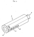
Fig. 2 is a perspective view showing the first embodiment.
Fig. 3 is an illustrative view of a primary part of the first
embodiment.
Fig. 4 is an exploded perspective view of the first embodiment.
Fig. 5 is an illustrative cross-sectional view of the primary part of
the first embodiment.
Fig. 6 is an illustrative cross-sectional view of the primary part of
the first embodiment.
Fig. 7 is an illustrative view of the primary part of the first
embodiment.
Fig. 8 is a cross-sectional view taken along the line A-A of Fig. 7.
Fig. 9 is an end view of the primary part of the first embodiment.
Fig. 10 is an illustrative view of the primary part of the first
embodiment.
Fig. 11 is an exploded perspective view of the primary part of the
first embodiment.
Fig. 12 is an illustrative cross-sectional view of the primary part of
the first embodiment.
Figs. 13(a) to 13(c) are schematic views of the operation of the
primary part of the first embodiment.
Figs. 14(a) to 14(c) are schematic views of the operation of the
primary part of the first embodiment.
Fig. 15 is a schematic view of the operation of the first embodiment.
Fig. 16 is a schematic view of the operation of the first embodiment.
Fig. 17 is an illustrative view of use condition of a second
embodiment.
Fig. 18 is a perspective view showing the second embodiment.
Fig. 19 is an exploded perspective view of a primary part of the
second embodiment.
Fig. 20 is an exploded perspective view of the primary part of the
second embodiment.
Fig. 21 is an illustrative cross-sectional view of the primary part of
the second embodiment.
Fig. 22 is an illustrative cross-sectional view of the primary part of
the second embodiment.
Fig. 23 is an illustrative cross-sectional view of the primary part of
the second embodiment.
Fig. 24 is an illustrative cross-sectional view of the primary part of
the second embodiment.
Fig. 25 is an illustrative view of the primary part of the second
embodiment.
Fig. 26 is an illustrative view of the primary part of the second
embodiment.
Fig. 27 is an end view of the primary part of the second embodiment.
Fig. 28 is an end view of the primary part of the second embodiment.
Fig. 29 is an exploded perspective view of the primary part of the
second embodiment.
Figs. 30(a) to 30(c) are schematic views of the operation of the
primary part of the second embodiment.
Figs. 31 (a) to 31 (c) are schematic views of the operation of the
primary part of the second embodiment.
Fig. 32 is a schematic view of the operation of the second
embodiment.
BEST MODE FOR EMBODYING THE INVENTION
A best possible mode for embodying the invention (how to embody
the invention in the best mode) will now be described in brief on the
basis of the drawings while showing the operational effect of the present
invention.
According to the present invention, when a second member 2 kept
under the coupled and closed condition is opened to a first member 1, in
a rotational range A1 from the coupled and closed position P1 to a
predetermined open angle position P2 rotated in the open direction, a
closing rotational biasing effect is generated to automatically close the
second member 2 to the coupled and closed position P1 relative to the
first member 1. Also, when the second member 2 is manually rotated in
the open direction relative to the first member 1 exceeding the above-described
predetermined open angle position P2, an open rotational
biasing effect is generated to automatically open the second member 2 up
to a predetermined open angle position P3 relative to the first member 1.
Namely, when the second member 2 is manually rotated in the
opening direction exceeding the predetermined open angle position P2
relative to the first member 1, the second member 2 is automatically
opened to the predetermined open angle position P3.
Accordingly, in the case where the hinge device according to the
present invention is applied to, for example, the above-described
collapsible type portable electronic equipment which is constituted by
pivotally coupling the body portion and the joint portion with each other,
for example, a finger of a hand holding the phone is inserted between the
body portion and the joint portion in use so that the joint portion is
rotated in the open direction relative to the body portion and the joint
portion is automatically opened due to the open rotational biasing effect.
Thus, the opening operation of the joint portion may readily and quickly
be attained, which is extremely useful.
Also, in the case where, in the rotational range A2 from the position
where the second member 2 is opened relative to the first member 1 to
the above-described predetermined open angle position P2 rotated in the
closing direction, a free stop effect is generated to hold the second
member 2 in any desired open angle position relative to the first member
1, it is possible to use the phone while stopping the second member 2
relative to the first member 1 in any desired angle of the phone which is
easy to use. This is much more useful.
[Embodiment 1]
A specific embodiment 1 of the present invention will be described
with reference to Figs. 1 to 16.
The embodiment 1 shows the case where a hinge device H according
to the present invention is applied to a collapsible type portable phone as
shown in Fig. 1. The hinge device H according to the present invention
is applied to a pivot mechanism in which a body portion provided with an
operating portion 14 is used as a first member 1 and a joint portion
provided with a display image field 15 is used as a second member 2 to
make it possible to take the condition from the closed condition where
the first member 1 and the second member 2 are coupled with each other
to the open condition (busy condition) where the second member 2 is
rotated to, for example, 120 degrees.
Then, when the second member 2 kept under the coupled and closed
condition is opened to a first member 1, in a rotational range A1 from the
coupled and closed position P1 to a predetermined open angle position
P2 rotated in the open direction, a closing rotational biasing effect is
generated to automatically close the second member 2 to the coupled and
closed position P1 relative to the first member 1 (see Fig. 15), when the
second member 2 is manually rotated in the open direction relative to the
first member 1 exceeding the above-described predetermined open angle
position P2, an open rotational biasing effect is generated to
automatically open the second member 2 at once up to a predetermined
open angle position P3 (maximum open angle position) relative to the
first member 1 (see Fig. 15), and furthermore, in a rotational range A2
from the position where the second member 2 is opened to the first
member 1 to the above-described predetermined open angle position P2
rotated in the closing direction, when the hand is released from the
second member 2, the second member 2 stops in the released position to
realize a free stop condition without any shake (see Fig. 16).
More specifically, in the present embodiment, a mounting hole 1a is
provided in a proximal portion of the first member 1, a mounting hole 2a
is provided adjacent to and in communication with the mounting hole 1a
also in a proximal portion of the second member 2, and the hinge device
H according to the present invention constituted into an axial part is
applied to the mounting holes 1a, 2a, respectively.
A casing 16 is fixed to the body portion 1 (first member) as a joint
portion constituting a part of a first joint member 3 having a rotation
preventing shape through the above-described mounting hole 1a, and a
member disposed in an exposed condition on one end side of this casing
16 is fixed as a mounting portion 17 constituting a part of a second joint
member 4 through the mounting hole 2a to the joint portion 2 (second
member) under the rotation prevented condition. This casing 16 has an
octagonal shape in cross section as shown. This is adapted to attain the
firm rotation preventing structure to the body portion 1. At the same
time, the octagonal shape is adapted as a shape which allows the parts to
be received effectively in its interior while providing the rotation
preventing structure.
An axial member 18 is provided at an inner hole 17a of the above-described
mounting portion 17 under the rotation prevented condition to
constitute the second joint member 4 provided with a cam portion 10 at
its tip end portion.
The axial member 18 relating to this second joint member 4 is
adapted so that the cam portion 10 is disposed rotatably within the casing
16 relating to the first joint member 3.
A closing member 19 is disposed on the other end side of the casing
16 relating to the first joint member 3, and furthermore, an engagement
member 20 having a cam engagement portion 11 facing and engaging the
cam portion 10 of the above-described second joint member 4 in a
concave and convex manner is provided within the casing 16. This
engagement member 20 is provided rotatably within the casing 16 and at
the same time provided slidably in the engagement and disengagement
direction within the casing 16.
A coiled spring 12 for biasing in the engaging direction is provided
as an engagement biasing member 12 within the casing 16 between the
engagement member 20 having this cam engagement portion 11 and the
closing member 19.
When the joint portion 2 kept under the coupled and closed condition
is opened to the body portion 1 by this engagement biasing member 12,
in the rotational range A1 from the coupled and closed position P1 to the
predetermined open angle position P2 rotated in the open direction, the
cam portion 10 and the cam engagement portion 11 are slipped down and
engaged with each other by biasing by the engagement biasing member
12 so that the closing rotational biasing effect for automatically closing
the joint portion 2 up to the coupled and closed position P1 relative to
the body portion 1 is generated. (This is referred to as the closing
structure portion 5 in the claims.)
On the other hand, a torque spring 13 is provided as a rotational
biasing member 13 to the axial member 18 having the cam portion 10, the
other end portion of the rotational biasing member 13 is coupled with a
joint member 21 to be disposed under a rotation prevented condition
within the casing 16, and accordingly, a biasing force for urging the
rotational biasing member 16 to rotate the casing 16 in turn functions as
a biasing force for rotating the axial member 18 (cam portion 10) by
keeping the condition that the casing 16 is fixed.
When the joint portion 2 is manually rotated to the body portion 1
exceeding the predetermined open angle position P2 in the opening
direction by this rotational biasing member 13, the cam portion 10 and
the cam engagement portion 11 are biased by the rotational biasing
member 13 and rotated together under the engagement condition without
disengagement therebetween as a closing structure portion 5 so that the
open rotational biasing effect is generated to automatically release the
joint portion 2 up to the predetermined open angle position P3 relative to
the body portion 1. (This is referred to as an opening structure portion 6
in the claims.)
Also, the cam engagement portion 11 is structured so that V-shaped
concave portions are formed at diametrically 180 degree opposite
positions, these concave portions are used as engagement portions with
which the above-described cam portion 10 engages, and an apex portion
(end face portion) of the cam portion 10 is brought into contact with an
apex portion (end face portion) between the concave portions in the
range of disengagement by the pressure force by the engagement biasing
member 12.
In the present embodiment, a frictional resistance increasing means is
provided for increasing a frictional resistance between the apex portion
of the cam portion 10 and the apex portion of the cam engagement
portion 11, and when the apex portion of the cam portion 10 and the apex
portion of the cam engagement portion 11 are brought into abutment with
each other, the engagement is held at a stop position by the increase of
the rotational resistance due to the frictional resistance increasing means
and the pressure force of the engagement biasing member 12 so far as the
members are not moved by hands even if the rotational biasing force of
the rotational biasing member 13 is applied.
Namely, the frictional resistance increasing means is structured so
that the abutment area between the apex portion of the cam portion 10
and the apex portion of the cam engagement portion 11 is formed to be
increased, whereby the frictional resistance between the apex portion of
the cam portion 10 and the apex portion of the cam engagement portion
11 which are brought into pressing contact with each other by the biasing
force of the engagement biasing member 12 is increased to realize the
free stop. In the present embodiment, in the rotational range A2 from the
position where the joint portion 2 is opened at maximum relative to the
body portion 1 to the above-described predetermined open angle position
P2 where the joint portion is rotated in the closed position, the free stop
effect is generated for holding the joint portion 2 at any desired open
angle position relative to the body portion 1.
More specifically, the sliding convex strips 11b each having a length
in the rotational direction of the cam engagement portion 11 are provided
in the convex portion of the cam engagement portion 11 and sliding
concave grooves 10b with which the sliding convex strips 11b are
brought into abutment and engagement are provided in the above-described
cam portion 10 whereby the abutment area between the apex
portion 10a of the cam portion 10 and the apex portion 11a of the cam
engagement portion 11 is increased and the frictional resistance between
the apex portion 10a of the cam portion 10 and the apex portion 11a of
the cam engagement portion 11 is enhanced.
Also, in the present embodiment, the above-described sliding convex
strips 11b each having a length in the rotational direction of this apex
portion 11a are provided substantially in the whole range of the apex
portion 11a of the engagement cam 11 whereby substantially in the whole
range where the above-described cam portion 10 is disengaged from the
cam engagement portion 11 and the apex portion 10a of the cam portion
10 and the apex portion 11a of the cam engagement portion 11 are
brought into contact with each other, the sliding convex strips 11b are in
abutment and engagement with the sliding concave grooves 10b under the
abutment condition.
More specifically, as shown in Fig. 11, the sliding convex strips 11b
are formed into arcuate shapes having a center at the center of the cam
engagement portion 11 substantially in the middle in the diametrical
direction of the apex portion 11a of the cam engagement portion 11 and
are formed into convex strips each having a length in the rotational
direction of the apex portion 11 a of the cam engagement portion 11.
Also, the sliding convex strips 11b and the sliding concave grooves
10b are formed into concave and convex shapes whose substantially
whole surface portions are to be kept in abutment in the coupling
engagement whereby the abutment areas of the apex portion 10a of the
cam portion 10 and the apex portion 11a of the cam engagement portion
11 are increased to enhance the frictional resistance to make it possible
to realize an extremely excellent free stop.
Namely, in the present embodiment, the extremely excellent free
stop operation may be exhibited substantially in the whole rotational
range where the cam engagement portion 11 is disengaged from the cam
portion 10 and the apex portion 11a of the cam engagement portion 11
and the apex portion 10a of the cam portion 10 are brought into abutment
with each other.
Also, in the present embodiment, a rotation preventing structure
portion 7 is provided for releaseably engaging with the above-described
closing structure portion 5 and for preventing the closing structure
portion 5 from rotating in the open direction by the opening structure
portion 6.
More specifically, in this rotation preventing structure portion 7, the
retainer member 8 for engaging and disengaging the engagement concave
portion 9 provided in the cam engagement portion 11 is provided in the
casing 16 constituting the first joint member 3. The retainer member 8 is
provided slidably away from the engagement direction under the rotation
prevented condition through the joint member 23 and at the same time
biased in the engagement direction by the engagement biasing member 22
as the coiled spring 22 for biasing in the engagement direction.
Also, the retainer member 8 is structured so that under the
engagement condition with the cam engagement portion 11, the
cooperative rotation between the cam portion 10 and the cam engagement
portion 11 by the rotational biasing member 13 is prevented, at the same
time, when this retainer member 8 is disengaged from the cam
engagement portion 11, the cooperative rotation between the cam portion
10 and the cam engagement portion 11 is allowed by the rotational
biasing member 13, and the engagement force of the retainer member 8 to
this engagement portion 11 is set up to such an engagement force that the
retainer member 8 is not disengaged from the cam engagement portion 11
by the biasing force of the rotational biasing member 13, and when the
joint portion 2 is manually rotated in the opening direction relative to the
body portion 1 exceeding the predetermined open angle position P2
against the closing rotational biasing force by the cam portion 10 and the
cam engagement portion 11, the retainer member 8 may be disengaged
from the cam engagement portion 11.
More specifically, in the retainer member 8, taper surfaces 8a are
formed at a tip end insertion portion to be inserted into the engagement
concave portion 9, and by the angle setup of these taper surfaces 8a,
when the joint portion 2 is manually rotated in the opening direction
relative to the body portion 1 exceeding the predetermined open angle
position P2 against the closing rotational biasing force by the cam
portion 10 and the cam engagement portion 11, the engagement force is
set up to such an engagement force that the retainer member 8 may be
disengaged from the engagement concave portion 9.
Also, in the present embodiments, contact surfaces which are inner
surfaces 9a of the engagement concave portion 9 and with which the
taper surfaces 8a of the retainer member 8 are brought into contact are
also formed in the taper surfaces 9a, the engagement force of the retainer
member 8 relative to the engagement concave portion 9 may be selected
suitably also by the angle setup of the taper surfaces 9a of this
engagement concave portion 9.
With such a structure, the present embodiment has the following
operational effect.
When the second member 2 kept under the coupled and closed
condition is opened to the first member 1, in the rotational range A1
from the coupled and closed position P1 to the predetermined open angle
position P2 rotated in the open direction, the closing rotational biasing
effect is generated to automatically close the second member 2 to the
coupled and closed position P1 relative to the first member 1. Also,
when the second member 2 is manually rotated in the open direction
relative to the first member 1 exceeding the predetermined open angle
position P2, the open rotational biasing effect is generated to
automatically open the second member 2 up to the predetermined open
angle position P3 relative to the first member 1. In the rotational range
A2 from the position where the second member 2 is opened relative to
the first member 1 to the predetermined open angle position P2 rotated in
the closing direction, the free stop effect is generated to hold the second
member 2 in any desired open angle position relative to the first member
1.
Namely, when the joint portion 2 is manually rotated in the open
direction exceeding the predetermined open angle position P2 relative to
the body portion 1, the joint portion 2 is automatically opened to the
predetermined open angle position P3. When the joint portion 2 kept
under the open condition to this predetermined open angle position P3 is
rotated in the closing direction, in the rotational range A2 up to the
predetermined open angle position P2, the joint portion 2 is always kept
under the slant condition relative to the body portion 1. Exceeding the
predetermined open angle position P2, the joint portion 1 is
automatically closed to the coupled and closed position P1.
The operation of the hinge device H in this case will be described on
the basis of the drawings.
First of all, when the second joint member 4 is rotated in the
direction of the arrow a in Fig. 13(b) by rotating the joint portion 2 in
the open direction relative to the body portion 1, the cam portion 10 and
the cam engagement portion 11 are cooperatively rotated in a somewhat
disengaged manner while they are to be disengaged from each other. In
this case, before the cam portion 10 and the cam engagement portion 11
are completely disengaged from each other, the retainer member 8 is
completely disengaged from the engagement concave portion 9 of the
cam engagement portion 11 while being retracted in the direction
indicated by an arrow b (see Fig. 13(b)). After all, the cam portion 10
and the cam engagement portion 11 are biased by the rotational biasing
member 13 and are cooperatively rotated under the engagement condition
in the direction indicated by the arrow a in Fig. 13(c). Thereafter, the
retainer member 8 biased by the engagement biasing member 22 is
advanced again in the direction c in Fig. 13 and fitted and engaged with
the engagement concave portion 9 (see Fig. 13(c)).
Until the cam portion 10 and the cam engagement portion 11 are
completely disengaged from each other, the closing rotational biasing
force for urging the joint portion 2 in the closing direction relative to the
body portion 1 is generated. After the retainer member 8 has been
completely disengaged from the engagement concave portion 9 of the
cam engagement portion 11, the open rotational biasing force for urging
the joint portion 2 in the open direction relative to the body portion 1 is
generated.
Subsequently, when the second joint member 4 is rotated in the
direction indicated by an arrow d in Fig. 14(b) by rotating the joint
portion 2 in the closing direction relative to the body portion 1, the cam
engagement portion 11 is retained and held by the retainer member 8 and
only the cam portion 10 is disengaged and rotated. (In the concave and
convex engagement between the cam portion 10 and the cam engagement
portion 11 in the direction in which the joint portion 2 is rotated in the
closing direction relative to the body portion 1, i.e., in the direction in
which only this cam portion 10 is rotated, the cam surface is set so that
the engagement force of the retainer member 8 to the cam engagement
portion 11 exceeds this engagement force whereby this cam engagement
portion 11 is not cooperatively rotated but kept under the rotation stop
condition. Accordingly, the cam portion 10 is rotated while being
disengaged from the cam engagement portion 11.) In this case, the cam
engagement portion 11 and the retainer member 8 are retracted in the
direction indicated by b in Fig. 14(b) against the engagement biasing
member 12 (and the engagement biasing member 22) so that the cam
portion 10 and the cam engagement portion 11 are completely disengaged
from each other (see Fig. 14(b)). Thereafter, until the second joint
member 4 is further rotated in the direction indicated by the arrow d in
Fig. 14 against the bias of the rotational biasing member 13 and the cam
portion 10 and the cam engagement portion 11 are in dropping
engagement with each other, the free stop effect is generated due to the
frictional resistance between the apex portion 10a of the cam portion 10
and the apex portion 11a of the cam engagement portion 11. After
passing through this free stop range, the cam portion 10 and the cam
engagement portion 11 are biased by the engagement biasing member 12
and are in dropping engagement with each other to thereby generate the
closing biasing rotational force whereby the joint portion 2 is completely
brought into closed condition (Fig. 14(c)).
Therefore, according to the present embodiment, in use, for example,
when the finger of the hand holding the phone is inserted between the
joint portion 2 and the body portion 1 so that the joint portion 2 is
rotated in the open direction relative to the body portion 1, the joint
portion 2 is automatically opened due to the open rotational biasing
operation. This is extremely useful because the opening operation of the
joint portion 2 may readily and quickly be performed.
Also, in this embodiment, in the rotational range A2 from the
position P3 where the joint portion 2 is opened at maximum by the open
rotational biasing effect relative to the body portion 1 to the
predetermined open angle position P2 where the joint portion is rotated
in the closing direction, the free stop effect is generated for holding the
second member 2 relative to the first member 1 at any desired angle
portion. Accordingly, it is possible to use the phone while the joint
portion 2 is stopped at a desired angle at which the phone is easy to use,
which is more useful.
[Embodiment 2]
A specific embodiment 2 of the present invention will be described
with reference to Figs. 17 to 32.
In the same manner as the above-described embodiment 1, the
embodiment 1 shows the case where a hinge device H according to the
present invention is applied to a collapsible type portable phone as
shown in Fig. 17. The hinge device H according to the present invention
is applied to a pivot mechanism in which a body portion provided with an
operating portion 14 is used as a first member 1 and a joint portion
provided with a display image field 15 is used as a second member 2 to
make it possible to take the condition from the closed condition where
the first member 1 and the second member 2 are coupled with each other
to the open condition (busy condition) where the second member 2 is
rotated to, for example, 120 degrees.
Then, when the second member 2 kept under the coupled and closed
condition is opened to a first member 1, in a rotational range A1 from the
coupled and closed position P1 to a predetermined open angle position
P2 rotated in the open direction, a closing rotational biasing effect is
generated to automatically close the second member 2 to the coupled and
closed position P1 relative to the first member 1 (see Fig. 32), when the
second member 2 is manually rotated in the open direction relative to the
first member 1 exceeding the above-described predetermined open angle
position P2, an open rotational biasing effect is generated to
automatically open the second member 2 at once up to a predetermined
open angle position P3 (maximum open angle position) relative to the
first member 1 (see Fig. 32), and furthermore, in a rotational range A2
from the position where the second member 2 is opened to the first
member 1 to the above-described predetermined open angle position P2
rotated in the closing direction, when the hand is released from the
second member 2, the second member 2 stops in the released position to
realize a free stop condition without any shake (see Fig. 32).
Also, the present embodiment is composed of a first hinge body H1
provided in a first pivot portion 25A provided at any one position of
right and left positions of a pivot joint portion 25 between the first
member 1 and the second member 2 and a second hinge member H2
provided in a second pivot portion 25B provided in the other position.
A closing structure portion 5 is provided in the first hinge member H1
for generating a closing rotational biasing effect for automatically
closing the second member 2 to the coupled and closed position P1
relative to the first member 1 when the second member 2 kept under the
coupled and closed condition relative to the first member 1 is opened, in
a rotational range A1 from the coupled and closed position P1 to a
predetermined open angle position P2 rotated in the open direction. At
the same time, an open structure portion 6 is provided in the second
hinge member H2 for generating the open rotational biasing effect for
automatically opening the second member 2 to the predetermined open
angle position P3 relative to the first member 1 by urging this closing
structure portion 5 in the rotational direction. A rotation preventing
structure portion 7 is provided for releaseably engaging with the closing
structure portion 5 and for preventing the rotation of the closing
structure portion 5 by the opening structure portion 6. A depression
button portion 26 for releasing the retention of the rotation preventing
structure portion 7 to this closing structure portion 5 is provided in the
rotation preventing structure portion 7.
More specifically, in the present embodiment, mounting holes 1b, 1c
are provided in right and left portions of a proximal end of the first
member 1, respectively. Also, mounting holes 2b, 2c adjacent to and in
communication with the mounting holes 1b, 1c are provided in right and
left portions of a proximal end of the second member 2, respectively. A
hinge device H (first hinge member H1 and second hinge member H2)
according to the present invention is applied as axial parts to the first
pivot portion 25A and the second pivot portion 25B constituted by these
respective mounting holes.
The first hinge member H1 will be described.
A casing 16 as a joint portion for constituting a part of a first joint
member 3 having a rotational preventing shape through the above-described
mounting hole 1b is fixed to the body portion 1 (first member).
A member disposed at one end side of this casing 16 in the exposed
condition as a mounting portion 17 constituting a second joint member 4
is fixed to the joint portion 2 (second member) through the mounting
hole 2b in a rotation prevented manner. This casing 16 has an octagonal
shape in cross section as shown. This is adapted to attain the firm
rotation preventing structure to the body portion 1. At the same time,
the octagonal shape is adapted as a shape which allows the parts to be
received effectively in its interior while providing the rotation
preventing structure.
An axial member 18 is provided at an inner hole 17a of the above-described
mounting portion 17 under the rotation prevented condition to
constitute the second joint member 4 provided with a cam portion 10.
The axial member 18 relating to this second joint member 4 is
adapted so that the cam portion 10 is disposed rotatably within the casing
16 relating to the first joint member 3.
A closing member 19 is disposed on the other end side of the casing
16 relating to the first joint member 3, and furthermore, an engagement
member 20 having a cam engagement portion 11 facing and engaging the
cam portion 10 of the above-described second joint member 4 in a
concave and convex manner is provided within the casing 16. This
engagement member 20 is provided rotatably within the casing 16 and at
the same time provided slidably in the disengagement direction within
the casing 16.
A coiled spring 12 for biasing in the engaging direction is provided
as an engagement biasing member 12 within the casing 16 between the
engagement member 20 having this cam engagement portion 11 and the
closing member 19. A tip end of this coiled spring 12 is coupled with a
joint member 23 to be described later and the cam engagement portion 11
is biased in the engagement direction through this joint member 23.
When the joint portion 2 kept under the coupled and closed condition
is opened to the body portion 1 by this engagement biasing member 12,
in the rotational range A1 from the coupled and closed position P1 to the
predetermined open angle position P2 rotated in the open direction, the
cam portion 10 and the cam engagement portion 11 are slipped down and
engaged with each other by biasing by the engagement biasing member
12 so that the closing rotational biasing effect for automatically closing
the joint portion 2 up to the coupled and closed position P1 relative to
the body portion 1 is generated. (This is referred to as the closing
structure portion 5 in the claims.)
Also, when the joint portion 2 is manually rotated to the body portion
1 exceeding the predetermined open angle position P2 in the opening
direction, the cam portion 10 and the cam engagement portion 11 are
adapted to be rotated together under the engagement condition without
disengagement therebetween.
Also, the cam engagement portion 11 is structured so that V-shaped
concave portions are formed at diametrically 180 degree opposite
positions, these concave portions are used as engagement portions with
which the above-described cam portion 10 engages, and an apex portion
(end face portion) of the cam portion 10 is brought into contact with an
apex portion (end face portion) between the concave portions in the
range of disengagement by the pressure force by the engagement biasing
member 12.
In the present embodiment, a frictional resistance increasing means is
provided for increasing a frictional resistance between the apex portion
of the cam portion 10 and the apex portion of the cam engagement
portion 11, and when the apex portion of the cam portion 10 and the apex
portion of the cam engagement portion 11 are brought into abutment with
each other, the engagement is held at a stop position by the increase of
the rotational resistance due to the frictional resistance increasing means
and the pressure force of the engagement biasing member 12 so far as the
members are not moved by hands even if the rotational biasing force of
the rotational biasing member 13 to be described later is applied.
Namely, the frictional resistance increasing means is structured so
that the abutment area between the apex portion of the cam portion 10
and the apex portion of the cam engagement portion 11 is formed to be
increased, whereby the frictional resistance between the apex portion of
the cam portion 10 and the apex portion of the cam engagement portion
11 which are brought into pressing contact with each other by the biasing
force of the engagement biasing member 12 is increased to realize the
free stop. In the present embodiment, in the rotational range A2 from the
position where the joint portion 2 is opened at maximum relative to the
body portion 1 to the above-described predetermined open angle position
P2 where the joint portion is rotated in the closed position, the free stop
effect is generated for holding the joint portion 2 at any desired open
angle position relative to the body portion 1.
More specifically, the sliding convex strips 11b each having a length
in the rotational direction of the cam engagement portion 11 are provided
in the convex portion of the cam engagement portion 11 and sliding
concave grooves 10b with which the sliding convex strips 11b are
brought into abutment and engagement are provided in the above-described
cam portion 10 whereby the abutment area between the apex
portion 10a of the cam portion 10 and the apex portion 11a of the cam
engagement portion 11 is increased and the frictional resistance between
the apex portion 10a of the cam portion 10 and the apex portion 11a of
the cam engagement portion 11 is enhanced.
Also, in the present embodiment, the above-described sliding convex
strips 11b each having a length in the rotational direction of this apex
portion 11a are provided substantially in the whole range of the apex
portion 11a of the engagement cam 11 whereby substantially in the whole
range where the above-described cam portion 10 is disengaged from the
cam engagement portion 11 and the apex portion 10a of the cam portion
10 and the apex portion 11a of the cam engagement portion 11 are
brought into contact with each other, the sliding convex strips 11b are in
abutment and engagement with the sliding concave grooves 10b under the
abutment condition.
More specifically, as shown in Fig. 29, the sliding convex strips 11b
are formed into arcuate shapes having a center at the center of the cam
engagement portion 11 substantially in the middle in the diametrical
direction of the apex portion 11a of the cam engagement portion 11 and
are formed into convex strips each having a length in the rotational
direction of the apex portion 11a of the cam engagement portion 11.
Also, the sliding convex strips 11b and the sliding concave grooves
10b are formed into concave and convex shapes whose substantially
whole surface portions are to be kept in abutment in the coupling
engagement whereby the abutment areas of the apex portion 10a of the
cam portion 10 and the apex portion 11a of the cam engagement portion
11 are increased to enhance the frictional resistance to make it possible
to realize an extremely excellent free stop.
Namely, in the present embodiment, the extremely excellent free
stop operation may be exhibited substantially in the whole rotational
range where the cam engagement portion 11 is disengaged from the cam
portion 10 and the apex portion 11a of the cam engagement portion 11
and the apex portion 10a of the cam portion 10 are brought into abutment
with each other.
Also, in the present embodiment, a rotation preventing structure
portion 7 is provided for releaseably engaging with the above-described
closing structure portion 5 and for preventing the closing structure
portion 5 from rotating in the open direction by the opening structure
portion 6 provided in the second hinge member H2 to be described later.
More specifically, in this rotation preventing structure portion 7,
the retainer member 8 for engaging and disengaging the engagement
concave portion 9 provided in the cam engagement portion 11 is provided
in the casing 16 constituting the first joint member 3. The retainer
member 8 is provided slidably away from the engagement direction under
the rotation prevented condition within the casing 16 through the joint
member 23 and at the same time biased in the engagement direction by
the engagement biasing member 22 as the coiled spring 22 for biasing in
the engagement direction.
Also, the retainer member 8 is structured so that under the
engagement condition with the cam engagement portion 11, the
cooperative rotation between the cam portion 10 and the cam engagement
portion 11 by the rotational biasing member 13 is prevented, at the same
time, when this retainer member 8 is disengaged from the cam
engagement portion 11, the cooperative rotation between the cam portion
10 and the cam engagement portion 11 is allowed by the rotational
biasing member 13, and the engagement force of the retainer member 8 to
this engagement portion 11 is set up to such an engagement force that the
retainer member 8 is not disengaged from the cam engagement portion 11
by the biasing force of the rotational biasing member 13, and when the
joint portion 2 is manually rotated in the opening direction relative to the
body portion 1 exceeding the predetermined open angle position P2
against the closing rotational biasing force by the cam portion 10 and the
cam engagement portion 11, the retainer member 8 may be disengaged
from the cam engagement portion 11.
More specifically, in the retainer member 8, taper surfaces 8a are
formed at a tip end insertion portion to be inserted into the engagement
concave portion 9, and by the angle setup of these taper surfaces 8a,
when the joint portion 2 is manually rotated in the opening direction
relative to the body portion 1 exceeding the predetermined open angle
position P2 against the closing rotational biasing force by the cam
portion 10 and the cam engagement portion 11, the engagement force is
set up to such an engagement force that the retainer member 8 is
slidingly moved against the engagement bias of the engagement biasing
member 22 so that the retainer member 8 may be disengaged from the
engagement concave portion 9.
Also, in the present embodiments, contact surfaces which are inner
surfaces 9a of the engagement concave portion 9 and with which the
taper surfaces 8a of the retainer member 8 are brought into contact are
also formed in the taper surfaces 9a, the engagement force of the retainer
member 8 relative to the engagement concave portion 9 may be selected
suitably also by the angle setup of the taper surfaces 9a of this
engagement concave portion 9.
Also, this rotation preventing structure portion 7 is provided with the
depression button portion 26 for releasing the retention of the retainer
member 8 to the above-described closing structure portion 5.
More specifically, this depression button portion 26 is structured so
that an axial portion 26b projects from an inner center position of a
depression portion 26a having a circular shape in frontal view. This
axial portion 26b is disposed to pass through an axial hole 18a provided
in the axial member 18 relating to the second joint member 4 in a pull-apart
preventing manner.
Also, the depression button portion 26 is provided with the axial
portion 26b slidable within the axial hole 18a of the axial member 18. A
tip end portion 26b' of the axial portion 26b is adapted to come into
contact with a tip end face 8b of the above-described retainer member 8.
Accordingly, when the depression button portion 26 is operated to be
depressed, the retainer member 8 is slidingly moved against the
engagement bias of the engagement biasing member 22 so that the
retention to the engagement concave portion 9 provided in the above-described
cam engagement portion 11 is released.
The second hinge member H2 will be described.
A casing 28 as a joint portion constituting a part of a third joint
member 27 having a rotation preventing shape through the above-described
mounting hole 1c is fixed to the body portion 1 (first member).
A member to be disposed in an exposed condition at one end side of this
casing 28 is fixed in a rotation prevented manner to the joint portion 2
(second member) through the mounting hole 2c as a mounting portion 30
constituting a part of a fourth joint member 29. This casing 28 has an
octagonal shape in cross section as shown. This is adapted to attain the
firm rotation preventing structure to the body portion 1. At the same
time, the octagonal shape is adapted as a shape which allows the parts to
be received effectively in its interior while providing the rotation
preventing structure.
Also, a joint member 31 to be coupled with a torque spring 13 as the
rotational biasing member 13 is provided in a rotation prevented
condition at a tip end portion to the inner hole 30a of the above-described
mounting portion 30. The other end portion of this rotational
biasing member 13 is coupled with a joint member 32 disposed in a
rotation prevented condition at the other end portion of the casing 28.
Accordingly, the biasing force of the rotational biasing member 13 for
rotating the casing 28 functions as a biasing force for rotating the fourth
joint member 29 with the casing 28 being fixed.
When the joint portion 2 is manually rotated to the body portion 1
exceeding the predetermined open angle position P2 in the opening
direction by this rotational biasing member 13 relating to the second
hinge member H2, or when the depression button portion 26 is operated
to be depressed, the cam portion 10 and the cam engagement portion 11
as the closing structure portion 5 relating to the above-described first
hinge member H1 are biased by the rotational biasing member 13 and
rotated together under the engagement condition without disengagement
therebetween so that the open rotational biasing effect is generated to
automatically release the joint portion 2 up to the predetermined open
angle position P3 relative to the body portion 1. (This is referred to as
an opening structure portion 6 in the claims.)
With such a structure, the present embodiment has the following
operational effect.
When the second member 2 kept under the coupled and closed
condition is opened to the first member 1, in the rotational range A1
from the coupled and closed position P1 to the predetermined open angle
position P2 rotated in the open direction, the closing rotational biasing
effect is generated to automatically close the second member 2 to the
coupled and closed position P1 relative to the first member 1. Also,
when the second member 2 is manually rotated in the open direction
relative to the first member 1 exceeding the predetermined open angle
position P2, the open rotational biasing effect is generated to
automatically open the second member 2 up to the predetermined open
angle position P3 relative to the first member 1. In the rotational range
A2 from the position where the second member 2 is opened relative to
the first member 1 to the predetermined open angle position P2 rotated in
the closing direction, the free stop effect is generated to hold the second
member 2 in any desired open angle position relative to the first member
1.
Namely, when the joint portion 2 is manually rotated in the open
direction exceeding the predetermined open angle position P2 relative to
the body portion 1, or when the depression button portion 26 is operated
to be depressed, the joint portion is automatically opened to the
predetermined open angle position P3. When the joint portion 2 kept
under the opened condition to this predetermined open angle position P3
is rotated in the closing direction, in the rotational range A2 up to the
predetermined open angle position P2, the joint portion 2 is always kept
under the slanted condition relative to the body portion 1. Exceeding the
predetermined open angle position P2, the joint portion 1 is
automatically closed to the coupled and closed position P1.
The operation of the hinge device H in this case will be described on
the basis of the drawings.
First of all, when the retainer member 8 is slidingly moved in the
direction indicated by an arrow a in Fig. 30(b) by operating and
depressing the depression button portion 26 relating to the first hinge
member H1, the cam portion 10 and the cam engagement portion 11 are
cooperatively rotated by the open rotational biasing force of the opening
structure portion 6 (rotational biasing member 13) relating to the second
hinge member H2 under the concave and convex engagement condition.
In this case, since the retainer member 8 is always biased to be engaged
by the engagement biasing member 22, after the cam portion 10 and the
cam engagement portion 11 have been cooperatively rotated through
about 180 degrees, the retainer member 8 is again engaged with the
engagement concave portion 9 of the cam engagement portion 11 (see
Fig. 30(c)).
Subsequently, when the second joint member 4 is rotated in the
direction indicated by an arrow d in Fig. 31(b) by rotating the joint
portion 2 in the closing direction relative to the body portion 1, the cam
engagement portion 11 is retained and held by the retainer member 8 and
only the cam portion 10 is disengaged and rotated. In this case, the cam
engagement portion 11 and the retainer member 8 are retracted in the
direction a in Fig. 31 (b) against the engagement biasing member 12 (and
the engagement biasing member 22) and the cam portion 10 and the cam
engagement portion 11 are completely disengaged from each other (see
Fig. 31(b)). Thereafter, while the second joint member 4 is further
rotated against the bias of the rotational biasing member 13 in the
direction indicated by the arrow d in Fig. 31 (c) and the cam portion 10
and the cam engagement portion 11 are in dropping engagement with
each other, a free stop effect is generated due to the friction resistance
between the apex portion 10a of the cam portion 10 and the apex portion
11 a of the cam engagement portion 11. After this free stop range, the
cam portion 10 and the cam engagement portion 11 are biased by the
engagement biasing member 12 and in dropping engagement with each
other to generate the closing biasing rotational force to thereby bring the
joint portion 2 to the completely closed condition to the body portion 1
(see Fig. 31(c)).
Next, the operation of the hinge device H in the case where the joint
portion 2 is manually opened to the body portion 1 will be described.
First of all, when the second joint member 4 is rotated by rotating the
joint portion 2 in the open direction relative to the body portion 1, the
cam portion 10 and the cam engagement portion 11 are cooperatively
rotated in a somewhat disengaged manner while they are to be
disengaged from each other. In this case, before the cam portion 10 and
the cam engagement portion 11 are completely disengaged from each
other, the retainer member 8 is completely disengaged from the
engagement concave portion 9 of the cam engagement portion 11 while
being retracted. Thereafter, the retainer member 8 biased by the
engagement biasing member 22 is advanced again and fitted and engaged
with the engagement concave portion 9.
Until the cam portion 10 and the cam engagement portion 11 are
completely disengaged from each other, the closing rotational biasing
force for urging the joint portion 2 in the closing direction relative to the
body portion 1 is generated. After the retainer member 8 has been
completely disengaged from the engagement concave portion 9 of the
cam engagement portion 11, the open rotational biasing force for urging
the joint portion 2 in the open direction relative to the body portion 1 is
generated.
Subsequently, when the second joint member 4 is rotated by rotating
the joint portion 2 in the closing direction relative to the body portion 1,
the cam engagement portion 11 is retained and held by the retainer
member 8 and only the cam portion 10 is disengaged and rotated. (In the
concave and convex engagement between the cam portion 10 and the cam
engagement portion 11 in the direction in which the joint portion 2 is
rotated in the closing direction relative to the body portion 1, i.e., in the
direction in which only this cam portion 10 is rotated, the cam surface is
set so that the engagement force of the retainer member 8 to the cam
engagement portion 11 exceeds this engagement force whereby this cam
engagement portion 11 is not cooperatively rotated but kept under the
rotation stop condition. Accordingly, the cam portion 10 is rotated while
being disengaged from the cam engagement portion 11.) In this case, the
cam engagement portion 11 and the retainer member 8 are retracted
against the engagement biasing member 12 (and the engagement biasing
member 22). Thereafter, until the second joint member 4 is further
rotated against the bias of the rotational biasing member 13 and the cam
portion 10 and the cam engagement portion 11 are in dropping
engagement with each other, the free stop effect is generated due to the
frictional resistance between the apex portion 10a of the cam portion 10
and the apex portion of the cam engagement portion 11. After passing
through this free stop range, the cam portion 10 and the cam engagement
portion 11 are biased by the engagement biasing member 12 and are in
dropping engagement with each other to thereby generate the closing
biasing power whereby the joint portion 2 is completely brought into
closed condition.
Therefore, according to the present embodiment, in use, for example,
when the finger of the hand holding the phone is inserted between the
joint portion 2 and the body portion 1 so that the joint portion 2 is
rotated in the open direction relative to the body portion 1, or the
depression button portion 26 is operated to be depressed, the joint
portion 2 is automatically opened due to the open rotational biasing
operation. This is extremely useful because the opening operation of the
joint portion 2 may readily and quickly be performed.
Also, in this embodiment, in the rotational range from the position P3
where the joint portion 2 is opened at maximum by the open rotational
biasing effect relative to the body portion 1 to the predetermined open
angle position P2 where the joint portion is rotated in the closing
direction, the free stop effect is generated for holding the second member
2 relative to the first member 1 at any desired angle portion.
Accordingly, it is possible to use the phone while the joint portion 2 is
stopped at a desired angle at which the phone is easy to use, which is
more useful.
Also, in the present embodiment, the hinge device H disposed to the
pivotal joint portion 25 between the body portion 1 and the joint portion
2 is the hinge structure (double hinge structure) composed of the first
hinge member H1 provided with the closing structure portion 5 and the
rotation preventing structure portion 7 and the second hinge member H2
provided with the opening structure portion 6. Therefore, the pivotal
joint portion 25 between the body portion 1 and the joint portion 2 for
providing this hinge device H may be divided on the right and left sides
and each pivotal portion (first pivotal portion 25A and second pivotal
portion 25B) may be made small in size. Since a vacant space S may be
formed between the right and left pivot portions (between the first pivot
portion 25A and the second pivot portion 25B), this vacant space S
serves to keep a sufficient space suitable for arranging wirings for
electrically connecting electronic parts to be disposed within the joint
portion 2 and electronic parts to be disposed within the body portion 1.
Such effect and the like may be ensured.
The other is the same as those of the embodiment 1.
Incidentally, the present invention is not limited to or by the
embodiments 1, 2 but the specific structure of each component may be
designed as desired.