EP1588919A1 - Fahrzeuglenkrad - Google Patents
Fahrzeuglenkrad Download PDFInfo
- Publication number
- EP1588919A1 EP1588919A1 EP05008315A EP05008315A EP1588919A1 EP 1588919 A1 EP1588919 A1 EP 1588919A1 EP 05008315 A EP05008315 A EP 05008315A EP 05008315 A EP05008315 A EP 05008315A EP 1588919 A1 EP1588919 A1 EP 1588919A1
- Authority
- EP
- European Patent Office
- Prior art keywords
- steering wheel
- insert
- vehicle steering
- skeleton
- receiving space
- Prior art date
- Legal status (The legal status is an assumption and is not a legal conclusion. Google has not performed a legal analysis and makes no representation as to the accuracy of the status listed.)
- Withdrawn
Links
- 238000003780 insertion Methods 0.000 claims description 5
- 230000037431 insertion Effects 0.000 claims description 5
- 230000000284 resting effect Effects 0.000 claims 1
- 239000006260 foam Substances 0.000 description 4
- 210000002414 leg Anatomy 0.000 description 4
- 239000002184 metal Substances 0.000 description 3
- 239000010985 leather Substances 0.000 description 2
- 229910000831 Steel Inorganic materials 0.000 description 1
- 238000005452 bending Methods 0.000 description 1
- 239000002131 composite material Substances 0.000 description 1
- 230000000694 effects Effects 0.000 description 1
- 230000005489 elastic deformation Effects 0.000 description 1
- 238000004519 manufacturing process Methods 0.000 description 1
- 239000000463 material Substances 0.000 description 1
- 239000010959 steel Substances 0.000 description 1
- 210000000689 upper leg Anatomy 0.000 description 1
- 239000002023 wood Substances 0.000 description 1
Images


Classifications
-
- B—PERFORMING OPERATIONS; TRANSPORTING
- B62—LAND VEHICLES FOR TRAVELLING OTHERWISE THAN ON RAILS
- B62D—MOTOR VEHICLES; TRAILERS
- B62D1/00—Steering controls, i.e. means for initiating a change of direction of the vehicle
- B62D1/02—Steering controls, i.e. means for initiating a change of direction of the vehicle vehicle-mounted
- B62D1/04—Hand wheels
- B62D1/11—Hand wheels incorporating energy-absorbing arrangements, e.g. by being yieldable or collapsible
-
- B—PERFORMING OPERATIONS; TRANSPORTING
- B62—LAND VEHICLES FOR TRAVELLING OTHERWISE THAN ON RAILS
- B62D—MOTOR VEHICLES; TRAILERS
- B62D1/00—Steering controls, i.e. means for initiating a change of direction of the vehicle
- B62D1/02—Steering controls, i.e. means for initiating a change of direction of the vehicle vehicle-mounted
- B62D1/04—Hand wheels
- B62D1/06—Rims, e.g. with heating means; Rim covers
-
- B—PERFORMING OPERATIONS; TRANSPORTING
- B62—LAND VEHICLES FOR TRAVELLING OTHERWISE THAN ON RAILS
- B62D—MOTOR VEHICLES; TRAILERS
- B62D7/00—Steering linkage; Stub axles or their mountings
- B62D7/22—Arrangements for reducing or eliminating reaction, e.g. vibration, from parts, e.g. wheels, of the steering system
- B62D7/222—Arrangements for reducing or eliminating reaction, e.g. vibration, from parts, e.g. wheels, of the steering system acting on the steering wheel
-
- Y—GENERAL TAGGING OF NEW TECHNOLOGICAL DEVELOPMENTS; GENERAL TAGGING OF CROSS-SECTIONAL TECHNOLOGIES SPANNING OVER SEVERAL SECTIONS OF THE IPC; TECHNICAL SUBJECTS COVERED BY FORMER USPC CROSS-REFERENCE ART COLLECTIONS [XRACs] AND DIGESTS
- Y10—TECHNICAL SUBJECTS COVERED BY FORMER USPC
- Y10T—TECHNICAL SUBJECTS COVERED BY FORMER US CLASSIFICATION
- Y10T74/00—Machine element or mechanism
- Y10T74/20—Control lever and linkage systems
- Y10T74/20576—Elements
- Y10T74/20732—Handles
- Y10T74/20834—Hand wheels
Definitions
- the invention relates to a vehicle steering wheel, with a skeleton and a in a storage room in the skeleton accommodated depositors to increase the Mass moment of inertia.
- the invention provides a vehicle steering wheel characterized by high stability and a simple production distinguishes.
- the insert While in the prior art, the skeleton is plastically deformed to the According to the invention, the insert itself is covered by the insert more stable skeleton bent and braced. A clip connection or another Safety measures for the depositor are thus unnecessary. Of course you can when inserting the insert and the associated bending also in addition still a plastic deformation of the same take place. Despite the plastic Deformation, however, the insert will still have enough elasticity to yourself self-biased to clamp in the receiving space.
- the depositor has a higher one Density as the skeleton and is preferably made of metal, but none Light metal.
- the receiving space preferably has an open insertion opening for the Depositors, which is also closed by no clip or the like. Only the sheathing of the steering wheel by means of foam and / or leather surrounds the Skeleton and the depositor.
- the contact points are preferably formed by projections on the Insert or, which is preferred, formed on the walls of the receiving space are.
- the preferred embodiment provides that the skeleton is closed rotates annularly in the steering wheel rim and the insert in the steering wheel rim, i. in the part of the steering wheel skeleton that runs through the steering wheel rim sits.
- the insert may be a ring extending in the annular skeleton along the Steering wheel rim extends.
- This ring can be self-contained and circulated would in this case together with the skeleton form a unit and the Significantly increase the stability of the steering wheel rim.
- the skeleton has seen in radial section in the area of the steering wheel rim a U-shaped, circumferential shape. Between the thighs of the "U” is then the insert pressed.
- the insert is undulating elastic bent in the annular receiving space along the steering wheel rim extends. This ensures that there are numerous contact points and the depositor bent several times in different directions, what its biasing effect improved.
- the insert is a rectangular one Has cross-sectional profile, namely in a section in the radial direction.
- Radial means in this case based on the steering wheel hub or steering shaft, which is through the hub extends.
- a vehicle steering wheel which is a to the steering shaft axis A extending hub 2, 4 spokes and an annular Steering wheel rim 6 has.
- the steering wheel is a composite component and has outside a skin of foam or leather. Also a wood casing or the like is conceivable.
- the outer foam layer 8 can be seen better.
- the stability of the steering wheel is by a provided in its interior, one-piece Steering wheel skeleton 10 reaches, which shown in Figure 1 with broken lines is.
- the steering wheel skeleton 10 has an annular portion in the steering wheel rim 6 and spoke portions extending from the steering wheel rim portion to a Extend hub portion.
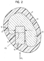
- the steering wheel skeleton 10 is in particular a die-cast part made of metal. It owns Preferably, to recognize in the section according to Figure 2, a U-shaped Cross section in the area of the steering wheel rim 6, with the "U" down (shown) or is open at the top and is bounded by two legs 12. in the The area of the spoke inlets is the U-shaped profile usually interrupted. Between the legs 12 results in a along the Steering wheel rim 6 with a continuous downwardly open insertion 13th provided receiving space 14 into which an insert 16 is pressed.
- the depositor 16 is a closed circumferential or slotted ring, which serves to increase the Mass moment of inertia is used in the steering wheel rim 6. alternative could of course also a plurality of circumferentially spaced ring segments be provided forming depositors.
- the insert 16 is only by a lateral clamping force F on him through the legs 12 is exercised, held in the receiving space 14.
- This clamping force is generated by the fact that the depositor, the rest of a rectangular cross-sectional profile has, from below between the legs 12 and the insertion hole 13 formed thereby is pressed into the skeleton 10 and in this case in a plane perpendicular to the axis A and transversely to the circumferential direction elastic, possibly even additionally slightly plastically deformed.
- the receiving space 14 extends, as can be seen in Figure 3, substantially a circular ring. He has but in the circumferential direction alternately on the inner wall 20 and the outer wall 22 rounded projections 24. At this Projections 24 is applied to the insert 16, and between the projections 24th column 26 result between the inner or outer wall 20, 22 and the Insert 16. The contact points where the walls 20, 22 and the Contact projections 24 and the insert 16 are denoted by 27. By the Projections 424, the insert 16 is wavy multiple times inward and bent outwards, so that there is a radial biasing force, by means of alone he is clamped and held in the receiving space 14.
- the insert can also vary from an axial view be convex radially outward curved sections composed.
- the invention provides, inter alia, the following advantages:
- the attachment of the insert 16 and its profile affect the Rigidity and strength of the steering wheel rim 6 positive, since the skeletal profile in the region of the steering wheel rim 6 in terms of increased rigidity better can be designed as in the use of an insert 16 with round profile.
Landscapes
- Engineering & Computer Science (AREA)
- Chemical & Material Sciences (AREA)
- Combustion & Propulsion (AREA)
- Transportation (AREA)
- Mechanical Engineering (AREA)
- Steering Controls (AREA)
Abstract
Description
- Figur 1 eine Draufsicht auf ein erfindungsgemäßes Fahrzeuglenkrad,
- Figur 2 eine radiale Schnittansicht durch den Lenkradkranz längs der Linie II-II in Figur 1 und
- Figur 3 eine Ansicht eines Abschnitts des Lenkradkranzes von unten ohne den Schaum und mit am Skelett befestigtem Einleger.
Claims (11)
- Fahrzeuglenkrad, mit
einem Skelett (10) und
einem in einem Aufnahmeraum (14) im Skelett (10) untergebrachten Einleger (16) zur Erhöhung des Massenträgheitsmoments,
dadurch gekennzeichnet, daß
der Einleger (16) durch die an ihm anliegenden Wände (20, 22) des Aufnahmeraums (14) elastisch gebogen und dadurch verspannt im Aufnahmeraum (16) geklemmt und darin gehaltert ist. - Fahrzeuglenkrad nach Anspruch 1, dadurch gekennzeichnet, daß der Aufnahmeraum (14) eine offene Einführöffnung (13) für den Einleger (16) hat.
- Fahrzeuglenkrad nach Anspruch 1 oder 2, dadurch gekennzeichnet, daß die Wände (20, 22) des Aufnahmeraums (14) und der Einleger (16) sich abschnittsweise berühren und zwischen den Berührstellen (27) Spalten (26) vorgesehen sind.
- Fahrzeuglenkrad nach Anspruch 3, dadurch gekennzeichnet, daß sich in Längsrichtung des Einlegers (16) gesehen auf seinen entgegengesetzt liegenden Seiten Berührstellen (27) in Umfangsrichtung auf gegenüberliegenden Wänden (20, 22) abwechseln.
- Fahrzeuglenkrad nach Anspruch 3 oder 4, dadurch gekennzeichnet, daß die Berührstellen (27) durch Vorsprünge (24) gebildet sind.
- Fahrzeuglenkrad nach Anspruch 5, dadurch gekennzeichnet, daß die Vorsprünge (24) an den Wänden (20, 22) des Aufnahmeraums (14) ausgeformt sind.
- Fahrzeuglenkrad nach einem der vorhergehenden Ansprüche, dadurch gekennzeichnet, daß das Skelett (10) geschlossen ringförmig im Lenkradkranz (6) umläuft und der Einleger (16) im Lenkradkranz (6) sitzt.
- Fahrzeuglenkrad nach einem der vorhergehenden Ansprüche, dadurch gekennzeichnet, daß der Einleger (16) ein Ring ist, der sich im ringförmigen Skelett (10) längs des Lenkradkranzes (6) erstreckt.
- Fahrzeuglenkrad nach Anspruch 8, dadurch gekennzeichnet, daß das Skelett (10) im Bereich des Lenkradkranzes (6) und im radialen Querschnitt gesehen ein U-förmiges Profil hat und zwischen seinen Schenkeln (12) der Einleger (16) geklemmt ist.
- Fahrzeuglenkrad nach Anspruch 8 oder 9, dadurch gekennzeichnet, daß sich der Einleger (16) wellenförmig elastisch gebogen im ringförmigen Aufnahmeraum (14) längs des Lenkradkranzes (6) erstreckt.
- Fahrzeuglenkrad nach einem der vorhergehenden Ansprüche, dadurch gekennzeichnet, daß der Einleger (16) ein rechteckiges Querschnittsprofil besitzt.
Applications Claiming Priority (2)
| Application Number | Priority Date | Filing Date | Title |
|---|---|---|---|
| DE202004006155U DE202004006155U1 (de) | 2004-04-19 | 2004-04-19 | Fahrzeuglenkrad |
| DE202004006155U | 2004-04-19 |
Publications (1)
| Publication Number | Publication Date |
|---|---|
| EP1588919A1 true EP1588919A1 (de) | 2005-10-26 |
Family
ID=32921316
Family Applications (1)
| Application Number | Title | Priority Date | Filing Date |
|---|---|---|---|
| EP05008315A Withdrawn EP1588919A1 (de) | 2004-04-19 | 2005-04-15 | Fahrzeuglenkrad |
Country Status (3)
| Country | Link |
|---|---|
| US (1) | US20050229740A1 (de) |
| EP (1) | EP1588919A1 (de) |
| DE (1) | DE202004006155U1 (de) |
Families Citing this family (4)
| Publication number | Priority date | Publication date | Assignee | Title |
|---|---|---|---|---|
| DE10123520C1 (de) * | 2001-05-15 | 2002-10-10 | Trw Automotive Safety Sys Gmbh | Verfahren zum Herstellen eines Lenkrades sowie Lenkrad |
| US20040011156A1 (en) * | 2002-07-16 | 2004-01-22 | Breed Automotive Technology, Inc. | High inertia - high mass steering wheel |
| US20080134832A1 (en) | 2006-12-12 | 2008-06-12 | Autoliv Asp, Inc. | Steering wheel with reduced vibration transmission |
| DE102017108429B4 (de) * | 2017-04-20 | 2024-09-19 | Joyson Safety Systems Germany Gmbh | Lenkrad für ein Kraftfahrzeug und Verfahren zum Herstellen eines Lenkrades für ein Kraftfahrzeug |
Citations (3)
| Publication number | Priority date | Publication date | Assignee | Title |
|---|---|---|---|---|
| JPH074251U (ja) * | 1993-06-18 | 1995-01-20 | 三菱自動車工業株式会社 | ステアリングホイール |
| JP2002053047A (ja) * | 2000-08-11 | 2002-02-19 | Nippon Plast Co Ltd | ステアリングホイール |
| US20030233905A1 (en) * | 2002-06-20 | 2003-12-25 | Bostick William E. | Vibration resistive steering wheel and method |
Family Cites Families (5)
| Publication number | Priority date | Publication date | Assignee | Title |
|---|---|---|---|---|
| US2014633A (en) * | 1931-03-31 | 1935-09-17 | Pannecoucke Gregoire Joscph | Reenforced wheel construction |
| DE600033C (de) * | 1932-11-29 | 1934-07-13 | Hans Oehmen | Lenkrad, insbesondere fuer Kraftfahrzeuge |
| US2215677A (en) * | 1938-10-20 | 1940-09-24 | Chrysler Corp | Steering wheel |
| DE19632317C1 (de) * | 1996-08-10 | 1998-01-29 | Mst Automotive Gmbh | Lenkradskelett für Kraftfahrzeuge |
| US6367351B2 (en) * | 1998-01-13 | 2002-04-09 | Toyoda Gosei Co., Ltd. | Steering wheel |
-
2004
- 2004-04-19 DE DE202004006155U patent/DE202004006155U1/de not_active Expired - Lifetime
-
2005
- 2005-04-15 EP EP05008315A patent/EP1588919A1/de not_active Withdrawn
- 2005-04-19 US US11/109,289 patent/US20050229740A1/en not_active Abandoned
Patent Citations (3)
| Publication number | Priority date | Publication date | Assignee | Title |
|---|---|---|---|---|
| JPH074251U (ja) * | 1993-06-18 | 1995-01-20 | 三菱自動車工業株式会社 | ステアリングホイール |
| JP2002053047A (ja) * | 2000-08-11 | 2002-02-19 | Nippon Plast Co Ltd | ステアリングホイール |
| US20030233905A1 (en) * | 2002-06-20 | 2003-12-25 | Bostick William E. | Vibration resistive steering wheel and method |
Non-Patent Citations (1)
| Title |
|---|
| PATENT ABSTRACTS OF JAPAN vol. 2002, no. 06 4 June 2002 (2002-06-04) * |
Also Published As
| Publication number | Publication date |
|---|---|
| US20050229740A1 (en) | 2005-10-20 |
| DE202004006155U1 (de) | 2004-08-26 |
Similar Documents
| Publication | Publication Date | Title |
|---|---|---|
| DE2426938C3 (de) | Stoßdämpfer | |
| DE1963299B2 (de) | Anschluss fuer mindestens ein druckmittelbeaufschlagtes, ein glattes ende aufweisendes rohrfoermiges element | |
| DE19807943C2 (de) | Rad für ein Fahrzeug, insbesondere Ersatzrad für ein Kraftfahrzeug | |
| DE3023977A1 (de) | Schalldaempfende anordnung fuer getrieberaeder. | |
| DE102007039858A1 (de) | Kugelgelenk | |
| DE2416512A1 (de) | Vibrator | |
| DE102004025234A1 (de) | An zwei entgegengesetzten Seiten mit Speichen verbundene Leichtbau-Felge | |
| EP1835199A2 (de) | Federbeinrohr aus flexibel gewalztem Blech | |
| EP2823971A1 (de) | Deckel für eine Radfelge sowie Rad mit einem solchen Deckel | |
| DE7620706U1 (de) | Feststellvorrichtung fuer fahrradlenker | |
| DE2030859A1 (de) | Rohrkupplung | |
| DE202004006155U1 (de) | Fahrzeuglenkrad | |
| DE102007043560A1 (de) | Fahrzeuglenkrad | |
| DE102016101693A1 (de) | Schalldämpfer für eine Abgasanlage | |
| DE6948314U (de) | Befestigungsvorrichtung. | |
| DE102018109757A1 (de) | Planetengetriebe mit mehrteiligem Planetenträger aufweisend zwei über massive Stegelemente abgestützte Trägerplatten | |
| DE3907067C2 (de) | ||
| DE102008046181A1 (de) | Antennenhalter für eine Satellitenschüssel | |
| DE10216349C1 (de) | Gehäuse für eine Airbageinrichtung mit Gehäuseversteifungen | |
| DE2530529B2 (de) | Speichenrad für Spielfahrzeuge | |
| DE19937539B4 (de) | Lenkrad für ein Kraftfahrzeug | |
| DE685828C (de) | Aus Blech gepresster Radstern | |
| DE2941607C2 (de) | Vorrichtung zum Reinigen eines Staubgasfilters | |
| DE102009004027A1 (de) | Lenkradskelett für ein Kraftfahrzeug | |
| DE202019100668U1 (de) | Zwei elastische Ringkörper aufweisende Drehachsenanordnung für eine Lenkrolle |
Legal Events
| Date | Code | Title | Description |
|---|---|---|---|
| PUAI | Public reference made under article 153(3) epc to a published international application that has entered the european phase |
Free format text: ORIGINAL CODE: 0009012 |
|
| AK | Designated contracting states |
Kind code of ref document: A1 Designated state(s): AT BE BG CH CY CZ DE DK EE ES FI FR GB GR HU IE IS IT LI LT LU MC NL PL PT RO SE SI SK TR |
|
| AX | Request for extension of the european patent |
Extension state: AL BA HR LV MK YU |
|
| 17P | Request for examination filed |
Effective date: 20060331 |
|
| AKX | Designation fees paid |
Designated state(s): DE ES FR IT |
|
| GRAP | Despatch of communication of intention to grant a patent |
Free format text: ORIGINAL CODE: EPIDOSNIGR1 |
|
| STAA | Information on the status of an ep patent application or granted ep patent |
Free format text: STATUS: THE APPLICATION IS DEEMED TO BE WITHDRAWN |
|
| 18D | Application deemed to be withdrawn |
Effective date: 20071102 |