EP1588877A1 - Lüftungsdüse - Google Patents
Lüftungsdüse Download PDFInfo
- Publication number
- EP1588877A1 EP1588877A1 EP05006509A EP05006509A EP1588877A1 EP 1588877 A1 EP1588877 A1 EP 1588877A1 EP 05006509 A EP05006509 A EP 05006509A EP 05006509 A EP05006509 A EP 05006509A EP 1588877 A1 EP1588877 A1 EP 1588877A1
- Authority
- EP
- European Patent Office
- Prior art keywords
- nozzle head
- nozzle
- ventilation
- ventilation nozzle
- housing
- Prior art date
- Legal status (The legal status is an assumption and is not a legal conclusion. Google has not performed a legal analysis and makes no representation as to the accuracy of the status listed.)
- Granted
Links
Images

Classifications
-
- B—PERFORMING OPERATIONS; TRANSPORTING
- B60—VEHICLES IN GENERAL
- B60H—ARRANGEMENTS OF HEATING, COOLING, VENTILATING OR OTHER AIR-TREATING DEVICES SPECIALLY ADAPTED FOR PASSENGER OR GOODS SPACES OF VEHICLES
- B60H1/00—Heating, cooling or ventilating devices
- B60H1/34—Nozzles; Air-diffusers
- B60H1/3414—Nozzles; Air-diffusers with means for adjusting the air stream direction
- B60H1/3435—Nozzles; Air-diffusers with means for adjusting the air stream direction using only a pivoting frame
- B60H1/3442—Nozzles; Air-diffusers with means for adjusting the air stream direction using only a pivoting frame the frame being spherical
Definitions
- the invention relates to a ventilation nozzle, in particular for installation in a motor vehicle with the features of the preamble of claim 1.
- U1 is a ventilation nozzle with a spherical shaped nozzle head known.
- the nozzle head has a plurality of outflow openings and is mounted rotatably and pivotally in the housing, so that the outflowing Air flow in his direction can be controlled.
- Storage is by a Housing section reaches, which extends around a part of the nozzle head strip-like, wherein the nozzle head is arranged with more than half of it in the housing.
- the Spherical shape forms the housing an undercut for the nozzle head, whereby a stop in all directions is achieved.
- the corresponding must Housing section slightly widened during assembly for joining the nozzle head or the nozzle head is slightly compressed.
- the invention is therefore based on the object, such a vent with to create improved storage.
- the Ventilation nozzle according to the invention has a spring element.
- This allows a Storage of the nozzle head with a defined force against a bearing surface, the no Has undercut.
- the housing serves with a circumferential Bund as an abutment, but it can also be provided a separate part.
- the Spring element can act in the outflow, then acts the covenant of the Housing on the outside of the nozzle head as an abutment.
- the Spring element but also be arranged on the outflow side and a in the housing lying waistband serve as an abutment. Basically, instead of a single Spring element also several annular over a circumference of the nozzle head arranged single spring elements may be arranged.
- the spring element is designed as a ring with spring arms, where instead of spring arms and ironing, Tabs or the like. Be arranged integrally on a circumferential spring element can.
- the nozzle head has on its the Side openings facing away from a plurality of locking recesses, in the engage the spring arms or the like. In the open state. This ensures that the nozzle head is held in the respectively set position, but at the same time by manual operation, a turn and pan remains possible.
- a corresponding valve can be replaced by a separate one Operating element, for example, a thumbwheel are actuated.
- the Nozzle head itself can be used as a control element for the valve.
- two options according to the available degrees of freedom to distinguish On the one hand is an opening or closing by turning the Nozzle head around the axis of Hauptausströmraum possible, on the other hand, the Valve over a displacement of the nozzle head relative to the housing.
- An embodiment of the invention is therefore the nozzle head via a universal joint connected to a rotary operated valve. Come as such a valve various designs in question.
- the vent has one or more openings in the closed state Covered by a valve body and are not covered in the open state.
- the Openings can be parallel and / or perpendicular to the axis of rotation of the valve be arranged.
- the vent nozzle preferably has an axial acting shutter mechanism. This ensures that the ventilation nozzle closed for example by pressure on the nozzle head and opened by train can be.
- the valve is designed such that the nozzle head a For example, has circumferential latching groove, in the closed state, the Spring element engages.
- the actual closing is done by a closing element, that corresponds in its geometry with the inflow opening of the nozzle head, ie is formed, for example, part-spherical.
- the spring element is simultaneously formed as a closing element, so that the ventilation nozzle can be formed from few parts.
- Nozzle head not only openings on the downstream side, but in addition Air guide elements, for example in the form of slats or the like.
- the ventilation nozzle 1 shown in Figure 1 is for installation, for example, in a not illustrated dashboard of a vehicle suitable. It consists of one cylindrical housing 2, a spherical nozzle head 3, a closing element 4 and an annular spring element 5 made of sheet metal, wherein all elements except for Closing element 4 are each shown only about half.
- the housing has a radially outwardly projecting, circumferential flange 6, which serves as a stop and Panel for installation in the dashboard is used.
- Radially inward protrudes a spherical curved collar 7 as a stop and seal for the nozzle head 3.
- the collar 7 acts as an abutment to the spring element 5, the nozzle head 3 axially in the outflow A suppressed.
- the Nozzle head 3 is rotated about the longitudinal axis of the air guide elements 8, this rotation acts via the universal joint 9 with drivers 16 on the closing element 4.
- the inflow side is located, for example, either in a cavity on the inside of a Dashboard, wherein in this cavity an overpressure relative to the Vehicle cabin prevails, or it is for example a ventilation hose over the Slipped upstream side 11 of the ventilation nozzle.
- the inflow side 11 is either opened (as in FIG. 1) or closed (as in FIG. 2). become. Since the closing element 4 in the nozzle head 3 to form the universal joint 9 is clipped and the nozzle head 3 is held by the spring element 5 is for the closing element 4 no additional part required for storage.
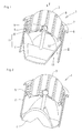
- FIGS. 3 and 4 show an alternative embodiment of the ventilation nozzle 1 a in FIG open ( Figure 3) and closed ( Figure 4) state shown.
- the spring element 5a and the closing element 4a are integral, whereby a further component is saved.
- the opening and closing is done by pressing or pulling the nozzle head 3a along the longitudinal direction of the housing 2a.
- the spring element 5a has several Spring arms 13, which the nozzle head 3a in the open state against the collar. 7 suppressed. This in turn allows pivoting and rotation of the nozzle head.
- the engagement of the spring arms in small locking recesses 14 results in a Locking in the respective position, whereby a special ease of use achieved becomes.
- the nozzle head 3a against the Outflow direction A is pressed into the housing 2a and the air guide elements 8 parallel to Longitudinal direction of the housing 2 aligned.
- the spring arms 13 engage in a circumferential latching groove 15 of the nozzle head 3a and hold it in this position.
- the valve 11a is in this embodiment by the closing element 5a and formed the nozzle head 3a itself.
- the spherically shaped closing element 5a corresponds in its shape and size of the inflow opening 16 of the nozzle head 3a and therefore covers completely off when closed.
Landscapes
- Physics & Mathematics (AREA)
- Thermal Sciences (AREA)
- Engineering & Computer Science (AREA)
- Mechanical Engineering (AREA)
- Nozzles (AREA)
- Air-Conditioning For Vehicles (AREA)
- Separation By Low-Temperature Treatments (AREA)
Abstract
Description
- Figur 1
- eine perspektivische Schnittdarstellung einer erfindungsgemäßen Lüftungsdüse in geöffnetem Zustand;
- Figur 2
- dieselbe Lüftungsdüse in geschlossenem Zustand;
- Figur 3
- eine weitere erfindungsgemäße Lüftungsdüse in perspektivischer Schnittdarstellung in geöffnetem Zustand; und
- Figur 4
- dieselbe Lüftungsdüse in geschlossenem Zustand.
Claims (9)
- Lüftungsdüse, insbesondere zum Einbau in ein Kraftfahrzeug, mit einem sphärisch geformten Düsenkopf (3, 3a) mit Ausströmöffnungen, welcher in einem Gehäuse (2, 2a) dreh- und schwenkbar gelagert ist, dadurch gekennzeichnet, dass die Lagerung ein Federelement (5, 5a) aufweist.
- Lüftungsdüse nach Anspruch 1, dadurch gekennzeichnet, dass das Gehäuse (2, 2a) einen Bund (7) als Gegenlager zum Federelement (5, 5a) aufweist.
- Lüftungsdüse nach Anspruch 1, dadurch gekennzeichnet, dass das Federelement (5a) als Ring mit Federarmen (13) ausgeführt ist.
- Lüftungsdüse nach Anspruch 3, dadurch gekennzeichnet, dass der Düsenkopf (3, 3a) eine Vielzahl von Rastvertiefungen (14) aufweist, in die die Federarme (13) im geöffneten Zustand eingreifen.
- Lüftungsdüse nach Anspruch 1, dadurch gekennzeichnet, dass der Düsenkopf über ein Kardangelenk (9) mit einem drehend betätigbaren Ventil (11) verbunden ist.
- Lüftungsdüse nach Anspruch 1, dadurch gekennzeichnet, dass die Lüftungsdüse (1a) durch einen in Bezug auf das Gehäuse (2a) axial wirkendes Ventil (11a) schließbar ist.
- Lüftungsdüse nach Anspruch 6, dadurch gekennzeichnet, dass das Ventil (11a) aus einer Rastrille (15) am Düsenkopf (3a), in den in der geschlossenen Stellung das Federelement (5a) eingreift, und ein mit der Anströmöffnung (16) des Düsenkopfes (3a) geometrisch korrespondierendes Schließelement (4a) gebildet ist.
- Lüftungsdüse nach Anspruch 7, dadurch gekennzeichnet, dass das Federelement (5a) und das Schließelement (4a) einstückig sind.
- Lüftungsdüse nach Anspruch 1, dadurch gekennzeichnet, dass der Düsenkopf (3, 3a) Luftleitelemente (8) aufweist.
Applications Claiming Priority (2)
| Application Number | Priority Date | Filing Date | Title |
|---|---|---|---|
| DE102004019755A DE102004019755A1 (de) | 2004-04-23 | 2004-04-23 | Lüftungsdüse |
| DE102004019755 | 2004-04-23 |
Publications (2)
| Publication Number | Publication Date |
|---|---|
| EP1588877A1 true EP1588877A1 (de) | 2005-10-26 |
| EP1588877B1 EP1588877B1 (de) | 2008-06-11 |
Family
ID=34934494
Family Applications (1)
| Application Number | Title | Priority Date | Filing Date |
|---|---|---|---|
| EP05006509A Expired - Lifetime EP1588877B1 (de) | 2004-04-23 | 2005-03-24 | Lüftungsdüse |
Country Status (5)
| Country | Link |
|---|---|
| US (1) | US7288023B2 (de) |
| EP (1) | EP1588877B1 (de) |
| JP (1) | JP2005306372A (de) |
| AT (1) | ATE398036T1 (de) |
| DE (2) | DE102004019755A1 (de) |
Cited By (4)
| Publication number | Priority date | Publication date | Assignee | Title |
|---|---|---|---|---|
| FR2924057A1 (fr) * | 2007-11-27 | 2009-05-29 | Peugeot Citroen Automobiles Sa | Aerateur assurant plusieurs fonctions d'aeration, notamment pour vehicule automobile |
| CN102186689A (zh) * | 2008-10-21 | 2011-09-14 | 施耐德博士塑料工厂有限公司 | 空气喷嘴 |
| CN105346357A (zh) * | 2014-07-30 | 2016-02-24 | 大众汽车有限公司 | 通风喷嘴 |
| CN106766066A (zh) * | 2017-02-14 | 2017-05-31 | 美的集团股份有限公司 | 顶出风结构、空调柜机、空调器和空调器的出风控制方法 |
Families Citing this family (34)
| Publication number | Priority date | Publication date | Assignee | Title |
|---|---|---|---|---|
| EP1344668B1 (de) * | 2002-03-15 | 2006-11-08 | TRW Automotive Electronics & Components GmbH & Co. KG | Belüftungsdüse für Lüftungssysteme |
| US20120195749A1 (en) | 2004-03-15 | 2012-08-02 | Airius Ip Holdings, Llc | Columnar air moving devices, systems and methods |
| DE102006062178B3 (de) * | 2006-12-22 | 2008-02-28 | Faurecia Innenraum Systeme Gmbh | Luftausströmer |
| DE102007019602B3 (de) * | 2007-04-24 | 2008-06-26 | Faurecia Innenraum Systeme Gmbh | Luftausströmer |
| DE102007058801A1 (de) | 2007-12-06 | 2009-06-10 | GM Global Technology Operations, Inc., Detroit | Lüftungsdüse |
| DE202008000059U1 (de) * | 2008-05-19 | 2008-12-24 | Dr. Schneider Kunststoffwerke Gmbh | Luftdüse |
| US9335061B2 (en) | 2008-05-30 | 2016-05-10 | Airius Ip Holdings, Llc | Columnar air moving devices, systems and methods |
| US9151295B2 (en) | 2008-05-30 | 2015-10-06 | Airius Ip Holdings, Llc | Columnar air moving devices, systems and methods |
| DE102008054360A1 (de) * | 2008-11-03 | 2010-05-06 | Bayerische Motoren Werke Aktiengesellschaft | Luftauslasseinrichtung für Fahrzeugklimaanlagen |
| WO2010114702A1 (en) | 2009-03-30 | 2010-10-07 | Airius Ip Holdings, Llc | Columnar air moving devices, systems and method |
| DE102010014575B3 (de) * | 2010-04-12 | 2011-11-17 | Trw Automotive Electronics & Components Gmbh | Luftausströmer |
| DE102010032233B3 (de) * | 2010-07-26 | 2011-07-21 | TRW Automotive Electronics & Components GmbH, 78315 | Luftausströmer |
| DE102010047261B4 (de) | 2010-10-01 | 2013-04-25 | Trw Automotive Electronics & Components Gmbh | Schaltvorrichtung |
| DE102011009423B4 (de) * | 2011-01-26 | 2017-07-20 | GM Global Technology Operations LLC (n. d. Ges. d. Staates Delaware) | Montagehilfe für eine Belüftungsdüse und einen Belüftungskanal eines Kraftfahrzeuges, Belüftungsdüse, Belüftungskanal und Armaturentafel |
| DE102011003489A1 (de) * | 2011-02-02 | 2012-08-02 | Behr Gmbh & Co. Kg | Luftdüse |
| AU2012271641B2 (en) | 2011-06-15 | 2015-10-01 | Airius Ip Holdings, Llc | Columnar air moving devices and systems |
| USD698916S1 (en) | 2012-05-15 | 2014-02-04 | Airius Ip Holdings, Llc | Air moving device |
| JP6104534B2 (ja) * | 2012-08-08 | 2017-03-29 | 豊和化成株式会社 | レジスタ |
| CA2875347C (en) | 2013-12-19 | 2022-04-19 | Airius Ip Holdings, Llc | Columnar air moving devices, systems and methods |
| CA2875339A1 (en) | 2013-12-19 | 2015-06-19 | Airius Ip Holdings, Llc | Columnar air moving devices, systems and methods |
| DE102015205017B4 (de) * | 2014-05-20 | 2023-10-12 | Ford Global Technologies, Llc | Kardanische Lagerung für eine Luftdüse |
| US10221861B2 (en) | 2014-06-06 | 2019-03-05 | Airius Ip Holdings Llc | Columnar air moving devices, systems and methods |
| USD805176S1 (en) | 2016-05-06 | 2017-12-12 | Airius Ip Holdings, Llc | Air moving device |
| USD820967S1 (en) | 2016-05-06 | 2018-06-19 | Airius Ip Holdings Llc | Air moving device |
| US10487852B2 (en) | 2016-06-24 | 2019-11-26 | Airius Ip Holdings, Llc | Air moving device |
| USD886275S1 (en) | 2017-01-26 | 2020-06-02 | Airius Ip Holdings, Llc | Air moving device |
| USD885550S1 (en) | 2017-07-31 | 2020-05-26 | Airius Ip Holdings, Llc | Air moving device |
| US11235643B2 (en) * | 2018-11-27 | 2022-02-01 | Scott Bradley Baker | Air vent assembly and control system |
| USD887541S1 (en) | 2019-03-21 | 2020-06-16 | Airius Ip Holdings, Llc | Air moving device |
| AU2020257205B2 (en) | 2019-04-17 | 2026-01-08 | Airius Ip Holdings, Llc | Air moving device with bypass intake |
| CN112793395B (zh) * | 2021-04-13 | 2021-07-02 | 宁波均胜群英汽车系统股份有限公司 | 一种手动操控的圆形出风口 |
| USD989928S1 (en) * | 2021-11-02 | 2023-06-20 | Classic Auto Air Manufacturing LP | Vent accessory for vehicle heating and air conditioning systems |
| USD989929S1 (en) * | 2021-11-02 | 2023-06-20 | Classic Auto Air Manufacturing LP | Vent accessory for vehicle heating and air conditioning systems |
| DE102022127572A1 (de) | 2022-10-19 | 2024-04-25 | Fischer Automotive Systems Gmbh & Co. Kg | Luftausströmer |
Citations (3)
| Publication number | Priority date | Publication date | Assignee | Title |
|---|---|---|---|---|
| DE1917945U (de) * | 1965-04-13 | 1965-06-16 | Happich Gmbh Gebr | Schnell montierbare lueftungsvorrichtung. |
| WO2003082617A1 (en) * | 2002-03-22 | 2003-10-09 | Michigan Medical Equipment Supplies, Inc. | Air outlet system |
| DE20313857U1 (de) * | 2003-09-06 | 2003-11-06 | OLHO-Technik Oleff & Holtmann oHG, 32584 Löhne | In ein Kraftfahrzeug einbaubare Lüftungsdüse |
Family Cites Families (8)
| Publication number | Priority date | Publication date | Assignee | Title |
|---|---|---|---|---|
| FR1446149A (fr) | 1964-08-22 | 1966-07-15 | Happich Gmbh Gebr | Perfectionnements aux dispositifs aérateurs |
| DE1917945A1 (de) | 1969-03-10 | 1970-10-15 | Stephan Erich | Schalungsnagel |
| GB8710157D0 (en) * | 1987-04-29 | 1987-06-03 | British Aerospace | Fluid flow control nozzles |
| DE19511652B4 (de) * | 1994-04-15 | 2004-01-15 | Volkswagen Ag | Luftausströmer für den Innenraum eines Fahrzeugs |
| US5921860A (en) * | 1996-04-01 | 1999-07-13 | Bowles Fluidics Corporation | Vehicle air outlet with uniform precision feel to operator |
| DE19807292B4 (de) * | 1997-03-01 | 2007-09-13 | Volkswagen Ag | Belüftungsvorrichtung für einen Innenraum |
| DE19947208C2 (de) * | 1999-10-01 | 2003-09-25 | Audi Ag | Schwenkbare Vorrichtung |
| ES2241904T3 (es) * | 2001-01-11 | 2005-11-01 | Goodrich Hella Aerospace Lighting Systems Gmbh | Dispositivo de salida de aire para vehiculo, especialmente para un avion. |
-
2004
- 2004-04-23 DE DE102004019755A patent/DE102004019755A1/de not_active Withdrawn
-
2005
- 2005-03-24 AT AT05006509T patent/ATE398036T1/de not_active IP Right Cessation
- 2005-03-24 EP EP05006509A patent/EP1588877B1/de not_active Expired - Lifetime
- 2005-03-24 DE DE502005004371T patent/DE502005004371D1/de not_active Expired - Lifetime
- 2005-04-19 US US11/108,955 patent/US7288023B2/en not_active Expired - Fee Related
- 2005-04-25 JP JP2005126536A patent/JP2005306372A/ja not_active Withdrawn
Patent Citations (3)
| Publication number | Priority date | Publication date | Assignee | Title |
|---|---|---|---|---|
| DE1917945U (de) * | 1965-04-13 | 1965-06-16 | Happich Gmbh Gebr | Schnell montierbare lueftungsvorrichtung. |
| WO2003082617A1 (en) * | 2002-03-22 | 2003-10-09 | Michigan Medical Equipment Supplies, Inc. | Air outlet system |
| DE20313857U1 (de) * | 2003-09-06 | 2003-11-06 | OLHO-Technik Oleff & Holtmann oHG, 32584 Löhne | In ein Kraftfahrzeug einbaubare Lüftungsdüse |
Cited By (6)
| Publication number | Priority date | Publication date | Assignee | Title |
|---|---|---|---|---|
| FR2924057A1 (fr) * | 2007-11-27 | 2009-05-29 | Peugeot Citroen Automobiles Sa | Aerateur assurant plusieurs fonctions d'aeration, notamment pour vehicule automobile |
| CN102186689A (zh) * | 2008-10-21 | 2011-09-14 | 施耐德博士塑料工厂有限公司 | 空气喷嘴 |
| CN102186689B (zh) * | 2008-10-21 | 2013-07-24 | 施耐德博士塑料工厂有限公司 | 空气喷嘴 |
| CN105346357A (zh) * | 2014-07-30 | 2016-02-24 | 大众汽车有限公司 | 通风喷嘴 |
| CN105346357B (zh) * | 2014-07-30 | 2018-04-24 | 大众汽车有限公司 | 通风喷嘴 |
| CN106766066A (zh) * | 2017-02-14 | 2017-05-31 | 美的集团股份有限公司 | 顶出风结构、空调柜机、空调器和空调器的出风控制方法 |
Also Published As
| Publication number | Publication date |
|---|---|
| EP1588877B1 (de) | 2008-06-11 |
| DE102004019755A1 (de) | 2005-11-17 |
| JP2005306372A (ja) | 2005-11-04 |
| ATE398036T1 (de) | 2008-07-15 |
| US7288023B2 (en) | 2007-10-30 |
| DE502005004371D1 (de) | 2008-07-24 |
| US20050239390A1 (en) | 2005-10-27 |
Similar Documents
| Publication | Publication Date | Title |
|---|---|---|
| EP1588877A1 (de) | Lüftungsdüse | |
| DE102010021431B4 (de) | Vorrichtung, um eine Flanschabdeckung mit einem Flansch in Eingriff zu bringen | |
| DE202016002951U1 (de) | Luftausströmer zur Anordnung im Innenraum eines Kraftfahrzeugs | |
| EP1634739B1 (de) | Luftausströmer, insbesondere für ein Fahrzeug | |
| EP1190188B1 (de) | Beidseitig wirkender antrieb für verstellvorrichtungen | |
| DE10321518B4 (de) | Luftdüse | |
| WO2013023633A2 (de) | Bodenwanne zum verbinden eines dachaufbau-kühlgerätes mit dem dach eines schaltschrankes | |
| EP1520738A1 (de) | Lamellendüse, insbesondere für eine Klimaanlage eines Kraftfahrzeugs | |
| DE10223660B4 (de) | Luftausströmer für ein Fahrzeug, insbesondere für ein Kraftfahrzeug | |
| EP1911616A1 (de) | Luftdüse zur Belüftung eines Fahrzeuginnenraums | |
| EP3606779B1 (de) | Luftleitelement mit reibelement und luftausströmer | |
| DE69102559T2 (de) | Scharnier mit integriertem Feststeller für Fahrzeugtüre oder andere Flügel. | |
| DE19847039C1 (de) | Absperrarmatur | |
| DE102009012267B4 (de) | Befüllanlage für Kfz-Klimaanlagen | |
| DE202006006792U1 (de) | Kraftfahrzeug-Klappe | |
| EP0966360A1 (de) | Frischluft-düseneinrichtung | |
| DE102018106843B4 (de) | Bedieneinrichtung | |
| DE102009051297B4 (de) | Lagerung eines drehbaren Bedienelementes an einem Luftausströmer | |
| DE102006054847A1 (de) | Luftausströmer mit einem Einsatz aus verformbaren Material | |
| DE102005055700B3 (de) | Ausströmdüse für den Fahrgastraum eines Kraftfahrzeuges | |
| EP1063110A2 (de) | Einstellbares Ventil für die Zufuhr von Kühlungsluft zu einem Handschuhfach | |
| DE19531248C2 (de) | Vorrichtung zur Betätigung von Klappen in einer Belüftungs-, Heizungs- oder Klimaanlage eines Kraftfahrzeugs | |
| DE202005002000U1 (de) | Luftdüse | |
| EP1728660B1 (de) | Vorrichtung zur Betätigung von Baugruppen, die ein Gehäuse mit einem Walzenkörper aufweisen | |
| EP2317190B1 (de) | Schliessmassadapter |
Legal Events
| Date | Code | Title | Description |
|---|---|---|---|
| PUAI | Public reference made under article 153(3) epc to a published international application that has entered the european phase |
Free format text: ORIGINAL CODE: 0009012 |
|
| AK | Designated contracting states |
Kind code of ref document: A1 Designated state(s): AT BE BG CH CY CZ DE DK EE ES FI FR GB GR HU IE IS IT LI LT LU MC NL PL PT RO SE SI SK TR |
|
| AX | Request for extension of the european patent |
Extension state: AL BA HR LV MK YU |
|
| 17P | Request for examination filed |
Effective date: 20060203 |
|
| AKX | Designation fees paid |
Designated state(s): AT BE BG CH CY CZ DE DK EE ES FI FR GB GR HU IE IS IT LI LT LU MC NL PL PT RO SE SI SK TR |
|
| GRAP | Despatch of communication of intention to grant a patent |
Free format text: ORIGINAL CODE: EPIDOSNIGR1 |
|
| GRAS | Grant fee paid |
Free format text: ORIGINAL CODE: EPIDOSNIGR3 |
|
| GRAA | (expected) grant |
Free format text: ORIGINAL CODE: 0009210 |
|
| AK | Designated contracting states |
Kind code of ref document: B1 Designated state(s): AT BE BG CH CY CZ DE DK EE ES FI FR GB GR HU IE IS IT LI LT LU MC NL PL PT RO SE SI SK TR |
|
| REG | Reference to a national code |
Ref country code: GB Ref legal event code: FG4D Free format text: NOT ENGLISH |
|
| REG | Reference to a national code |
Ref country code: CH Ref legal event code: EP |
|
| REF | Corresponds to: |
Ref document number: 502005004371 Country of ref document: DE Date of ref document: 20080724 Kind code of ref document: P |
|
| REG | Reference to a national code |
Ref country code: IE Ref legal event code: FG4D Free format text: LANGUAGE OF EP DOCUMENT: GERMAN |
|
| PG25 | Lapsed in a contracting state [announced via postgrant information from national office to epo] |
Ref country code: SI Free format text: LAPSE BECAUSE OF FAILURE TO SUBMIT A TRANSLATION OF THE DESCRIPTION OR TO PAY THE FEE WITHIN THE PRESCRIBED TIME-LIMIT Effective date: 20080611 Ref country code: FI Free format text: LAPSE BECAUSE OF FAILURE TO SUBMIT A TRANSLATION OF THE DESCRIPTION OR TO PAY THE FEE WITHIN THE PRESCRIBED TIME-LIMIT Effective date: 20080611 |
|
| PG25 | Lapsed in a contracting state [announced via postgrant information from national office to epo] |
Ref country code: NL Free format text: LAPSE BECAUSE OF FAILURE TO SUBMIT A TRANSLATION OF THE DESCRIPTION OR TO PAY THE FEE WITHIN THE PRESCRIBED TIME-LIMIT Effective date: 20080611 Ref country code: PL Free format text: LAPSE BECAUSE OF FAILURE TO SUBMIT A TRANSLATION OF THE DESCRIPTION OR TO PAY THE FEE WITHIN THE PRESCRIBED TIME-LIMIT Effective date: 20080611 |
|
| NLV1 | Nl: lapsed or annulled due to failure to fulfill the requirements of art. 29p and 29m of the patents act | ||
| PG25 | Lapsed in a contracting state [announced via postgrant information from national office to epo] |
Ref country code: PT Free format text: LAPSE BECAUSE OF FAILURE TO SUBMIT A TRANSLATION OF THE DESCRIPTION OR TO PAY THE FEE WITHIN THE PRESCRIBED TIME-LIMIT Effective date: 20081111 Ref country code: LT Free format text: LAPSE BECAUSE OF FAILURE TO SUBMIT A TRANSLATION OF THE DESCRIPTION OR TO PAY THE FEE WITHIN THE PRESCRIBED TIME-LIMIT Effective date: 20080611 Ref country code: IS Free format text: LAPSE BECAUSE OF FAILURE TO SUBMIT A TRANSLATION OF THE DESCRIPTION OR TO PAY THE FEE WITHIN THE PRESCRIBED TIME-LIMIT Effective date: 20081011 Ref country code: ES Free format text: LAPSE BECAUSE OF FAILURE TO SUBMIT A TRANSLATION OF THE DESCRIPTION OR TO PAY THE FEE WITHIN THE PRESCRIBED TIME-LIMIT Effective date: 20080922 Ref country code: SE Free format text: LAPSE BECAUSE OF FAILURE TO SUBMIT A TRANSLATION OF THE DESCRIPTION OR TO PAY THE FEE WITHIN THE PRESCRIBED TIME-LIMIT Effective date: 20080911 |
|
| REG | Reference to a national code |
Ref country code: IE Ref legal event code: FD4D |
|
| PG25 | Lapsed in a contracting state [announced via postgrant information from national office to epo] |
Ref country code: SK Free format text: LAPSE BECAUSE OF FAILURE TO SUBMIT A TRANSLATION OF THE DESCRIPTION OR TO PAY THE FEE WITHIN THE PRESCRIBED TIME-LIMIT Effective date: 20080611 Ref country code: RO Free format text: LAPSE BECAUSE OF FAILURE TO SUBMIT A TRANSLATION OF THE DESCRIPTION OR TO PAY THE FEE WITHIN THE PRESCRIBED TIME-LIMIT Effective date: 20080611 |
|
| PLBE | No opposition filed within time limit |
Free format text: ORIGINAL CODE: 0009261 |
|
| STAA | Information on the status of an ep patent application or granted ep patent |
Free format text: STATUS: NO OPPOSITION FILED WITHIN TIME LIMIT |
|
| PG25 | Lapsed in a contracting state [announced via postgrant information from national office to epo] |
Ref country code: IE Free format text: LAPSE BECAUSE OF FAILURE TO SUBMIT A TRANSLATION OF THE DESCRIPTION OR TO PAY THE FEE WITHIN THE PRESCRIBED TIME-LIMIT Effective date: 20080611 Ref country code: BG Free format text: LAPSE BECAUSE OF FAILURE TO SUBMIT A TRANSLATION OF THE DESCRIPTION OR TO PAY THE FEE WITHIN THE PRESCRIBED TIME-LIMIT Effective date: 20080911 Ref country code: EE Free format text: LAPSE BECAUSE OF FAILURE TO SUBMIT A TRANSLATION OF THE DESCRIPTION OR TO PAY THE FEE WITHIN THE PRESCRIBED TIME-LIMIT Effective date: 20080611 Ref country code: DK Free format text: LAPSE BECAUSE OF FAILURE TO SUBMIT A TRANSLATION OF THE DESCRIPTION OR TO PAY THE FEE WITHIN THE PRESCRIBED TIME-LIMIT Effective date: 20080611 |
|
| 26N | No opposition filed |
Effective date: 20090312 |
|
| BERE | Be: lapsed |
Owner name: FISCHER AUTOMOTIVE SYSTEMS G.M.B.H. Effective date: 20090331 |
|
| PG25 | Lapsed in a contracting state [announced via postgrant information from national office to epo] |
Ref country code: MC Free format text: LAPSE BECAUSE OF NON-PAYMENT OF DUE FEES Effective date: 20090331 |
|
| REG | Reference to a national code |
Ref country code: CH Ref legal event code: PL |
|
| GBPC | Gb: european patent ceased through non-payment of renewal fee |
Effective date: 20090324 |
|
| PG25 | Lapsed in a contracting state [announced via postgrant information from national office to epo] |
Ref country code: LI Free format text: LAPSE BECAUSE OF NON-PAYMENT OF DUE FEES Effective date: 20090331 Ref country code: CH Free format text: LAPSE BECAUSE OF NON-PAYMENT OF DUE FEES Effective date: 20090331 |
|
| PG25 | Lapsed in a contracting state [announced via postgrant information from national office to epo] |
Ref country code: BE Free format text: LAPSE BECAUSE OF NON-PAYMENT OF DUE FEES Effective date: 20090331 |
|
| PG25 | Lapsed in a contracting state [announced via postgrant information from national office to epo] |
Ref country code: GB Free format text: LAPSE BECAUSE OF NON-PAYMENT OF DUE FEES Effective date: 20090324 |
|
| PG25 | Lapsed in a contracting state [announced via postgrant information from national office to epo] |
Ref country code: AT Free format text: LAPSE BECAUSE OF NON-PAYMENT OF DUE FEES Effective date: 20090324 |
|
| PG25 | Lapsed in a contracting state [announced via postgrant information from national office to epo] |
Ref country code: GR Free format text: LAPSE BECAUSE OF FAILURE TO SUBMIT A TRANSLATION OF THE DESCRIPTION OR TO PAY THE FEE WITHIN THE PRESCRIBED TIME-LIMIT Effective date: 20080912 |
|
| PG25 | Lapsed in a contracting state [announced via postgrant information from national office to epo] |
Ref country code: LU Free format text: LAPSE BECAUSE OF NON-PAYMENT OF DUE FEES Effective date: 20090324 |
|
| PGFP | Annual fee paid to national office [announced via postgrant information from national office to epo] |
Ref country code: CZ Payment date: 20110322 Year of fee payment: 7 |
|
| PG25 | Lapsed in a contracting state [announced via postgrant information from national office to epo] |
Ref country code: HU Free format text: LAPSE BECAUSE OF FAILURE TO SUBMIT A TRANSLATION OF THE DESCRIPTION OR TO PAY THE FEE WITHIN THE PRESCRIBED TIME-LIMIT Effective date: 20081212 |
|
| PG25 | Lapsed in a contracting state [announced via postgrant information from national office to epo] |
Ref country code: TR Free format text: LAPSE BECAUSE OF FAILURE TO SUBMIT A TRANSLATION OF THE DESCRIPTION OR TO PAY THE FEE WITHIN THE PRESCRIBED TIME-LIMIT Effective date: 20080611 |
|
| PG25 | Lapsed in a contracting state [announced via postgrant information from national office to epo] |
Ref country code: CY Free format text: LAPSE BECAUSE OF FAILURE TO SUBMIT A TRANSLATION OF THE DESCRIPTION OR TO PAY THE FEE WITHIN THE PRESCRIBED TIME-LIMIT Effective date: 20080611 |
|
| PGFP | Annual fee paid to national office [announced via postgrant information from national office to epo] |
Ref country code: FR Payment date: 20120403 Year of fee payment: 8 |
|
| PGFP | Annual fee paid to national office [announced via postgrant information from national office to epo] |
Ref country code: IT Payment date: 20120327 Year of fee payment: 8 |
|
| PG25 | Lapsed in a contracting state [announced via postgrant information from national office to epo] |
Ref country code: CZ Free format text: LAPSE BECAUSE OF NON-PAYMENT OF DUE FEES Effective date: 20130324 |
|
| REG | Reference to a national code |
Ref country code: FR Ref legal event code: ST Effective date: 20131129 |
|
| PG25 | Lapsed in a contracting state [announced via postgrant information from national office to epo] |
Ref country code: FR Free format text: LAPSE BECAUSE OF NON-PAYMENT OF DUE FEES Effective date: 20130402 |
|
| PG25 | Lapsed in a contracting state [announced via postgrant information from national office to epo] |
Ref country code: IT Free format text: LAPSE BECAUSE OF NON-PAYMENT OF DUE FEES Effective date: 20130324 |
|
| PGFP | Annual fee paid to national office [announced via postgrant information from national office to epo] |
Ref country code: DE Payment date: 20140117 Year of fee payment: 10 |
|
| REG | Reference to a national code |
Ref country code: DE Ref legal event code: R119 Ref document number: 502005004371 Country of ref document: DE |
|
| PG25 | Lapsed in a contracting state [announced via postgrant information from national office to epo] |
Ref country code: DE Free format text: LAPSE BECAUSE OF NON-PAYMENT OF DUE FEES Effective date: 20151001 |