EP1588793B1 - Dispositifs de traitement a laser - Google Patents
Dispositifs de traitement a laser Download PDFInfo
- Publication number
- EP1588793B1 EP1588793B1 EP03777262A EP03777262A EP1588793B1 EP 1588793 B1 EP1588793 B1 EP 1588793B1 EP 03777262 A EP03777262 A EP 03777262A EP 03777262 A EP03777262 A EP 03777262A EP 1588793 B1 EP1588793 B1 EP 1588793B1
- Authority
- EP
- European Patent Office
- Prior art keywords
- light
- laser light
- transmitting hole
- laser
- beam expander
- Prior art date
- Legal status (The legal status is an assumption and is not a legal conclusion. Google has not performed a legal analysis and makes no representation as to the accuracy of the status listed.)
- Expired - Lifetime
Links
- 238000012545 processing Methods 0.000 title claims abstract description 103
- 230000003287 optical effect Effects 0.000 claims abstract description 21
- 238000010521 absorption reaction Methods 0.000 claims description 32
- 210000001747 pupil Anatomy 0.000 claims description 7
- 230000001678 irradiating effect Effects 0.000 claims description 5
- XUIMIQQOPSSXEZ-UHFFFAOYSA-N Silicon Chemical compound [Si] XUIMIQQOPSSXEZ-UHFFFAOYSA-N 0.000 description 31
- 229910052710 silicon Inorganic materials 0.000 description 30
- 239000010703 silicon Substances 0.000 description 30
- 238000010438 heat treatment Methods 0.000 description 12
- 238000003672 processing method Methods 0.000 description 12
- 230000014509 gene expression Effects 0.000 description 10
- 239000000758 substrate Substances 0.000 description 10
- 238000005520 cutting process Methods 0.000 description 8
- 101100008049 Caenorhabditis elegans cut-5 gene Proteins 0.000 description 6
- 238000002834 transmittance Methods 0.000 description 6
- 238000002474 experimental method Methods 0.000 description 5
- 239000011521 glass Substances 0.000 description 5
- 239000000463 material Substances 0.000 description 5
- 230000010287 polarization Effects 0.000 description 4
- 239000004065 semiconductor Substances 0.000 description 4
- 238000010586 diagram Methods 0.000 description 3
- 210000000887 face Anatomy 0.000 description 3
- 238000003384 imaging method Methods 0.000 description 3
- 238000000034 method Methods 0.000 description 3
- 230000002093 peripheral effect Effects 0.000 description 3
- 238000012546 transfer Methods 0.000 description 3
- 230000000903 blocking effect Effects 0.000 description 2
- 238000003776 cleavage reaction Methods 0.000 description 2
- 238000003913 materials processing Methods 0.000 description 2
- 230000010355 oscillation Effects 0.000 description 2
- 238000005086 pumping Methods 0.000 description 2
- 230000007017 scission Effects 0.000 description 2
- 230000035882 stress Effects 0.000 description 2
- RZVAJINKPMORJF-UHFFFAOYSA-N Acetaminophen Chemical compound CC(=O)NC1=CC=C(O)C=C1 RZVAJINKPMORJF-UHFFFAOYSA-N 0.000 description 1
- 229910012463 LiTaO3 Inorganic materials 0.000 description 1
- 238000002679 ablation Methods 0.000 description 1
- 230000004075 alteration Effects 0.000 description 1
- 229910021417 amorphous silicon Inorganic materials 0.000 description 1
- 238000005452 bending Methods 0.000 description 1
- 238000011109 contamination Methods 0.000 description 1
- 239000013078 crystal Substances 0.000 description 1
- 238000002425 crystallisation Methods 0.000 description 1
- 230000008025 crystallization Effects 0.000 description 1
- 238000011156 evaluation Methods 0.000 description 1
- 230000002349 favourable effect Effects 0.000 description 1
- 230000004927 fusion Effects 0.000 description 1
- 238000003698 laser cutting Methods 0.000 description 1
- 230000031700 light absorption Effects 0.000 description 1
- 239000013307 optical fiber Substances 0.000 description 1
- 238000000059 patterning Methods 0.000 description 1
- 239000005297 pyrex Substances 0.000 description 1
- 238000007493 shaping process Methods 0.000 description 1
- 230000008646 thermal stress Effects 0.000 description 1
- 238000003466 welding Methods 0.000 description 1
Images


Classifications
-
- B—PERFORMING OPERATIONS; TRANSPORTING
- B23—MACHINE TOOLS; METAL-WORKING NOT OTHERWISE PROVIDED FOR
- B23K—SOLDERING OR UNSOLDERING; WELDING; CLADDING OR PLATING BY SOLDERING OR WELDING; CUTTING BY APPLYING HEAT LOCALLY, e.g. FLAME CUTTING; WORKING BY LASER BEAM
- B23K26/00—Working by laser beam, e.g. welding, cutting or boring
- B23K26/02—Positioning or observing the workpiece, e.g. with respect to the point of impact; Aligning, aiming or focusing the laser beam
- B23K26/04—Automatically aligning, aiming or focusing the laser beam, e.g. using the back-scattered light
-
- B—PERFORMING OPERATIONS; TRANSPORTING
- B28—WORKING CEMENT, CLAY, OR STONE
- B28D—WORKING STONE OR STONE-LIKE MATERIALS
- B28D1/00—Working stone or stone-like materials, e.g. brick, concrete or glass, not provided for elsewhere; Machines, devices, tools therefor
- B28D1/22—Working stone or stone-like materials, e.g. brick, concrete or glass, not provided for elsewhere; Machines, devices, tools therefor by cutting, e.g. incising
- B28D1/221—Working stone or stone-like materials, e.g. brick, concrete or glass, not provided for elsewhere; Machines, devices, tools therefor by cutting, e.g. incising by thermic methods
-
- B—PERFORMING OPERATIONS; TRANSPORTING
- B23—MACHINE TOOLS; METAL-WORKING NOT OTHERWISE PROVIDED FOR
- B23K—SOLDERING OR UNSOLDERING; WELDING; CLADDING OR PLATING BY SOLDERING OR WELDING; CUTTING BY APPLYING HEAT LOCALLY, e.g. FLAME CUTTING; WORKING BY LASER BEAM
- B23K26/00—Working by laser beam, e.g. welding, cutting or boring
- B23K26/02—Positioning or observing the workpiece, e.g. with respect to the point of impact; Aligning, aiming or focusing the laser beam
- B23K26/06—Shaping the laser beam, e.g. by masks or multi-focusing
- B23K26/064—Shaping the laser beam, e.g. by masks or multi-focusing by means of optical elements, e.g. lenses, mirrors or prisms
- B23K26/066—Shaping the laser beam, e.g. by masks or multi-focusing by means of optical elements, e.g. lenses, mirrors or prisms by using masks
-
- B—PERFORMING OPERATIONS; TRANSPORTING
- B23—MACHINE TOOLS; METAL-WORKING NOT OTHERWISE PROVIDED FOR
- B23K—SOLDERING OR UNSOLDERING; WELDING; CLADDING OR PLATING BY SOLDERING OR WELDING; CUTTING BY APPLYING HEAT LOCALLY, e.g. FLAME CUTTING; WORKING BY LASER BEAM
- B23K26/00—Working by laser beam, e.g. welding, cutting or boring
- B23K26/14—Working by laser beam, e.g. welding, cutting or boring using a fluid stream, e.g. a jet of gas, in conjunction with the laser beam; Nozzles therefor
- B23K26/1462—Nozzles; Features related to nozzles
-
- B—PERFORMING OPERATIONS; TRANSPORTING
- B23—MACHINE TOOLS; METAL-WORKING NOT OTHERWISE PROVIDED FOR
- B23K—SOLDERING OR UNSOLDERING; WELDING; CLADDING OR PLATING BY SOLDERING OR WELDING; CUTTING BY APPLYING HEAT LOCALLY, e.g. FLAME CUTTING; WORKING BY LASER BEAM
- B23K26/00—Working by laser beam, e.g. welding, cutting or boring
- B23K26/36—Removing material
- B23K26/40—Removing material taking account of the properties of the material involved
-
- B—PERFORMING OPERATIONS; TRANSPORTING
- B23—MACHINE TOOLS; METAL-WORKING NOT OTHERWISE PROVIDED FOR
- B23K—SOLDERING OR UNSOLDERING; WELDING; CLADDING OR PLATING BY SOLDERING OR WELDING; CUTTING BY APPLYING HEAT LOCALLY, e.g. FLAME CUTTING; WORKING BY LASER BEAM
- B23K26/00—Working by laser beam, e.g. welding, cutting or boring
- B23K26/50—Working by transmitting the laser beam through or within the workpiece
- B23K26/53—Working by transmitting the laser beam through or within the workpiece for modifying or reforming the material inside the workpiece, e.g. for producing break initiation cracks
-
- B—PERFORMING OPERATIONS; TRANSPORTING
- B28—WORKING CEMENT, CLAY, OR STONE
- B28D—WORKING STONE OR STONE-LIKE MATERIALS
- B28D5/00—Fine working of gems, jewels, crystals, e.g. of semiconductor material; apparatus or devices therefor
-
- B—PERFORMING OPERATIONS; TRANSPORTING
- B23—MACHINE TOOLS; METAL-WORKING NOT OTHERWISE PROVIDED FOR
- B23K—SOLDERING OR UNSOLDERING; WELDING; CLADDING OR PLATING BY SOLDERING OR WELDING; CUTTING BY APPLYING HEAT LOCALLY, e.g. FLAME CUTTING; WORKING BY LASER BEAM
- B23K2101/00—Articles made by soldering, welding or cutting
- B23K2101/36—Electric or electronic devices
- B23K2101/40—Semiconductor devices
-
- B—PERFORMING OPERATIONS; TRANSPORTING
- B23—MACHINE TOOLS; METAL-WORKING NOT OTHERWISE PROVIDED FOR
- B23K—SOLDERING OR UNSOLDERING; WELDING; CLADDING OR PLATING BY SOLDERING OR WELDING; CUTTING BY APPLYING HEAT LOCALLY, e.g. FLAME CUTTING; WORKING BY LASER BEAM
- B23K2103/00—Materials to be soldered, welded or cut
- B23K2103/50—Inorganic material, e.g. metals, not provided for in B23K2103/02 – B23K2103/26
Claims (3)
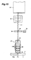
- Appareil de traitement laser (20) permettant d'irradier un objet de type tranche (1) à traiter avec une lumière laser (L1) tout en situant un point de convergence de lumière (P) dans l'objet de façon à former une région modifiée (7), l'appareil comprenant :un dilatateur de faisceau (34) permettant d'agrandir une taille de faisceau de la lumière laser émise depuis une source de lumière laser (22) ;une lentille de condenseur (31) permettant de converger la lumière laser incidente sur celle-ci au moyen du dilatateur de faisceau dans l'objet ; et caractérisé par :un support de lentille (29) supportant la lentille de condenseur (31) et comprenant un premier orifice d'émission de lumière (32) permettant de rendre la lumière laser incidente sur la lentille de condenseur ;dans lequel un organe de diaphragme (38) comportant un second orifice d'émission de lumière (39) permettant de diminuer et d'émettre la lumière laser est disposé sur un chemin optique de la lumière laser (L1) connectant le dilatateur de faisceau (34) et le premier orifice d'émission de lumière (32) l'un à l'autre et est agencé de manière à être séparé du support de lentille (29), de sorte que l'émission de chaleur de l'organe de diaphragme (38) au support de lentille (29) est empêchée,dans lequel, lorsque la lumière laser (L1) émise depuis le dilatateur de faisceau (34) est une lumière parallèle, le second orifice d'émission de lumière (39) présente un diamètre non supérieur à celui du premier orifice d'émission de lumière (32), etdans lequel le premier orifice d'émission de lumière (32) agit comme une pupille d'entrée de la lumière laser (L1) à la lentille de condenseur (31), et la région modifiée (7) est formée par une absorption multiphotonique dans l'objet se produisant dans une condition où le pic de densité de puissance de la lumière laser est 1 x 10⁸ W/cm2 ou plus.
- Appareil de traitement laser (20) permettant d'irradier un objet de type tranche (1) à traiter avec une lumière laser (L1) tout en situant un point de convergence de lumière (P) dans l'objet de façon à former une région modifiée (7), l'appareil comprenant :un dilatateur de faisceau (34) permettant d'agrandir une taille de faisceau de la lumière laser émise depuis une source de lumière laser (22) ;une lentille de condenseur (31) permettant de converger la lumière laser incidente sur celle-ci au moyen du dilatateur de faisceau dans l'objet ; et caractérisé par :un support de lentille (29) supportant la lentille de condenseur (31) et comprenant un premier orifice d'émission de lumière (32) permettant de rendre la lumière laser incidente sur la lentille de condenseur ;dans lequel un organe de diaphragme (38) comportant un second orifice d'émission de lumière (39) permettant de diminuer et d'émettre la lumière laser est disposé sur un chemin optique de la lumière laser (L1) connectant le dilatateur de faisceau (34) et le premier orifice d'émission de lumière (32) l'un à l'autre et est agencé de façon à être séparé du support de lentille (29), de sorte que l'émission de chaleur entre l'organe de diaphragme (38) et le support de lentille (29) est empêchée,dans lequel, lorsque la source de lumière laser (22) émet la lumière laser (L1) à un diamètre de faisceau ϕ0 et un angle de divergence 2θ0, et que le dilatateur de faisceau (34) agrandit la taille de faisceau de la lumière laser par un grossissement M et émet la lumière laser à un angle de divergence 2θ1;en supposant que d1 est la distance entre une partie de sortie (22a) de la source de lumière laser (22) et une partie d'entrée (34a) du dilatateur de faisceau, que d2 est la distance entre une partie de sortie (34b) du dilatateur de faisceau et une ouverture d'entrée (39a) du second orifice d'émission de lumière (39), et que d3 est la distance entre l'ouverture d'entrée (39a) du second orifice d'émission de lumière (39) et une ouverture d'entrée (32a) du premier orifice d'émission de lumière (32) ; etsoit ϕL le diamètre du premier orifice d'émission de lumière (32) et ϕS le diamètre du second orifice d'émission de lumière (39) ;ϕL et ϕS satisfont la relation

etdans lequel le premier orifice d'émission de lumière (32) agit comme une pupille d'entrée de la lumière laser (L1) à la lentille de condenseur (31), et la région modifiée (7) est formée par une absorption multiphotonique dans l'objet se produisant dans une condition où le pic de densité de puissance de la lumière laser est 1 x 10⁸ W/cm2 ou plus. - Appareil de traitement laser (20) permettant d'irradier un objet de type tranche (1) à traiter avec une lumière laser (L1) tout en situant un point de convergence de lumière (P) dans l'objet de façon à former une région modifiée (7), l'appareil comprenant :un dilatateur de faisceau (34) permettant d'agrandir une taille de faisceau de la lumière laser émise depuis une source de lumière laser (22) ;une lentille de condenseur (31) permettant de converger la lumière laser incidente sur celle-ci au moyen du dilatateur de faisceau dans l'objet ; et caractérisé par :un support de lentille (29) supportant la lentille de condenseur (31) et comprenant un premier orifice d'émission de lumière (32) permettant de rendre la lumière laser incidente sur la lentille de condenseur ;dans lequel un organe de diaphragme (38) comportant un second orifice d'émission de lumière (39) permettant de diminuer et d'émettre la lumière laser est disposé sur un chemin optique de la lumière laser (L1) connectant le dilatateur de faisceau (34) et le premier orifice d'émission de lumière (32) l'un à l'autre et est agencé de façon à être séparé du support de lentille (29), de sorte que l'émission de chaleur de l'organe de diaphragme (38) au support de lentille (29) est empêchée,dans lequel, lorsque la source de lumière laser (22) émet la lumière laser (L1) à un diamètre de faisceau ϕ0 et à un angle de divergence 2θ0, et que le dilatateur de faisceau (34) agrandit la taille de faisceau de la lumière laser par un grossissement M et émet la lumière laser à un angle de convergence de 2θ1 ;en supposant que d1 est la distance entre une partie de sortie (22a) de la source de lumière laser (22) et une partie d'entrée (34a) du dilatateur de faisceau (34), que d2 est la distance entre une partie de sortie (34b) du dilatateur de faisceau (34) et une ouverture d'entrée (39a) du second orifice d'émission de lumière (39), et que d3 est la distance entre l'ouverture d'entrée (39a) du second orifice d'émission de lumière (39) et l'ouverture d'entrée (32a) du premier orifice d'émission de lumière (32) ; etsoit ϕL le diamètre du premier orifice d'émission de lumière (32), et ϕS le diamètre du second orifice d'émission de lumière (39) ;ϕL et ϕS satisfont la relation de

etdans lequel le premier orifice d'émission de lumière (32) agit comme une pupille d'entrée de la lumière laser (L1) à la lentille de condenseur (31), et la région modifiée (7) est formée par une absorption multiphotonique dans l'objet se produisant dans une condition où le pic de densité de puissance de la lumière laser est 1 x 10⁸ W/cm2 ou plus.
Applications Claiming Priority (3)
| Application Number | Priority Date | Filing Date | Title |
|---|---|---|---|
| JP2002354234 | 2002-12-05 | ||
| JP2002354234 | 2002-12-05 | ||
| PCT/JP2003/015555 WO2004050291A1 (fr) | 2002-12-05 | 2003-12-04 | Dispositif de traitement a laser |
Publications (3)
| Publication Number | Publication Date |
|---|---|
| EP1588793A1 EP1588793A1 (fr) | 2005-10-26 |
| EP1588793A4 EP1588793A4 (fr) | 2008-09-03 |
| EP1588793B1 true EP1588793B1 (fr) | 2012-03-21 |
Family
ID=32463334
Family Applications (1)
| Application Number | Title | Priority Date | Filing Date |
|---|---|---|---|
| EP03777262A Expired - Lifetime EP1588793B1 (fr) | 2002-12-05 | 2003-12-04 | Dispositifs de traitement a laser |
Country Status (9)
| Country | Link |
|---|---|
| US (1) | US7489454B2 (fr) |
| EP (1) | EP1588793B1 (fr) |
| JP (1) | JP3683580B2 (fr) |
| KR (1) | KR101119262B1 (fr) |
| CN (1) | CN100445014C (fr) |
| AT (1) | ATE550129T1 (fr) |
| AU (1) | AU2003289188A1 (fr) |
| ES (1) | ES2381254T3 (fr) |
| WO (1) | WO2004050291A1 (fr) |
Families Citing this family (50)
| Publication number | Priority date | Publication date | Assignee | Title |
|---|---|---|---|---|
| JP4659300B2 (ja) | 2000-09-13 | 2011-03-30 | 浜松ホトニクス株式会社 | レーザ加工方法及び半導体チップの製造方法 |
| CN1328002C (zh) | 2002-03-12 | 2007-07-25 | 浜松光子学株式会社 | 加工对象物切割方法 |
| TWI326626B (en) * | 2002-03-12 | 2010-07-01 | Hamamatsu Photonics Kk | Laser processing method |
| ATE534142T1 (de) * | 2002-03-12 | 2011-12-15 | Hamamatsu Photonics Kk | Verfahren zum auftrennen eines substrats |
| TWI520269B (zh) | 2002-12-03 | 2016-02-01 | Hamamatsu Photonics Kk | Cutting method of semiconductor substrate |
| JP2004188422A (ja) * | 2002-12-06 | 2004-07-08 | Hamamatsu Photonics Kk | レーザ加工装置及びレーザ加工方法 |
| FR2852250B1 (fr) | 2003-03-11 | 2009-07-24 | Jean Luc Jouvin | Fourreau de protection pour canule, un ensemble d'injection comportant un tel fourreau et aiguille equipee d'un tel fourreau |
| DE60315515T2 (de) * | 2003-03-12 | 2007-12-13 | Hamamatsu Photonics K.K., Hamamatsu | Laserstrahlbearbeitungsverfahren |
| ES2523432T3 (es) * | 2003-07-18 | 2014-11-25 | Hamamatsu Photonics K.K. | Chip semiconductor cortado |
| JP4563097B2 (ja) | 2003-09-10 | 2010-10-13 | 浜松ホトニクス株式会社 | 半導体基板の切断方法 |
| JP4601965B2 (ja) * | 2004-01-09 | 2010-12-22 | 浜松ホトニクス株式会社 | レーザ加工方法及びレーザ加工装置 |
| JP4598407B2 (ja) * | 2004-01-09 | 2010-12-15 | 浜松ホトニクス株式会社 | レーザ加工方法及びレーザ加工装置 |
| JP4509578B2 (ja) * | 2004-01-09 | 2010-07-21 | 浜松ホトニクス株式会社 | レーザ加工方法及びレーザ加工装置 |
| WO2005098916A1 (fr) | 2004-03-30 | 2005-10-20 | Hamamatsu Photonics K.K. | Procede de traitement au laser et pucee semiconducteur |
| KR101109860B1 (ko) * | 2004-08-06 | 2012-02-21 | 하마마츠 포토닉스 가부시키가이샤 | 레이저 가공 방법, 가공 대상물 절단 방법 및 반도체 장치 |
| WO2006043690A1 (fr) * | 2004-10-20 | 2006-04-27 | Semiconductor Energy Laboratory Co., Ltd. | Procédé d’irradiation laser, appareil d’irradiation laser et procédé de fabrication de dispositif semi-conducteur |
| US7626138B2 (en) * | 2005-09-08 | 2009-12-01 | Imra America, Inc. | Transparent material processing with an ultrashort pulse laser |
| JP4762653B2 (ja) * | 2005-09-16 | 2011-08-31 | 浜松ホトニクス株式会社 | レーザ加工方法及びレーザ加工装置 |
| JP4907965B2 (ja) * | 2005-11-25 | 2012-04-04 | 浜松ホトニクス株式会社 | レーザ加工方法 |
| JP4804911B2 (ja) * | 2005-12-22 | 2011-11-02 | 浜松ホトニクス株式会社 | レーザ加工装置 |
| JP4907984B2 (ja) * | 2005-12-27 | 2012-04-04 | 浜松ホトニクス株式会社 | レーザ加工方法及び半導体チップ |
| ES2428826T3 (es) * | 2006-07-03 | 2013-11-11 | Hamamatsu Photonics K.K. | Procedimiento de procesamiento por láser y chip |
| JP5183892B2 (ja) | 2006-07-03 | 2013-04-17 | 浜松ホトニクス株式会社 | レーザ加工方法 |
| JP5145673B2 (ja) * | 2006-08-30 | 2013-02-20 | 住友電気工業株式会社 | レーザ加工方法およびレーザ加工装置 |
| KR101428823B1 (ko) * | 2006-09-19 | 2014-08-11 | 하마마츠 포토닉스 가부시키가이샤 | 레이저 가공 방법 및 레이저 가공 장치 |
| JP4954653B2 (ja) | 2006-09-19 | 2012-06-20 | 浜松ホトニクス株式会社 | レーザ加工方法 |
| JP5101073B2 (ja) * | 2006-10-02 | 2012-12-19 | 浜松ホトニクス株式会社 | レーザ加工装置 |
| JP4964554B2 (ja) * | 2006-10-03 | 2012-07-04 | 浜松ホトニクス株式会社 | レーザ加工方法 |
| JP5132911B2 (ja) * | 2006-10-03 | 2013-01-30 | 浜松ホトニクス株式会社 | レーザ加工方法 |
| US8735770B2 (en) * | 2006-10-04 | 2014-05-27 | Hamamatsu Photonics K.K. | Laser processing method for forming a modified region in an object |
| JP5336054B2 (ja) * | 2007-07-18 | 2013-11-06 | 浜松ホトニクス株式会社 | 加工情報供給装置を備える加工情報供給システム |
| JP5449665B2 (ja) | 2007-10-30 | 2014-03-19 | 浜松ホトニクス株式会社 | レーザ加工方法 |
| JP5134928B2 (ja) * | 2007-11-30 | 2013-01-30 | 浜松ホトニクス株式会社 | 加工対象物研削方法 |
| JP5054496B2 (ja) * | 2007-11-30 | 2012-10-24 | 浜松ホトニクス株式会社 | 加工対象物切断方法 |
| AU2009238798B2 (en) * | 2008-04-25 | 2013-03-07 | Inix Ltd. | Laser hair-loss treatment device |
| JP5692969B2 (ja) | 2008-09-01 | 2015-04-01 | 浜松ホトニクス株式会社 | 収差補正方法、この収差補正方法を用いたレーザ加工方法、この収差補正方法を用いたレーザ照射方法、収差補正装置、及び、収差補正プログラム |
| JP5254761B2 (ja) | 2008-11-28 | 2013-08-07 | 浜松ホトニクス株式会社 | レーザ加工装置 |
| JP5241525B2 (ja) | 2009-01-09 | 2013-07-17 | 浜松ホトニクス株式会社 | レーザ加工装置 |
| JP5241527B2 (ja) | 2009-01-09 | 2013-07-17 | 浜松ホトニクス株式会社 | レーザ加工装置 |
| KR101757937B1 (ko) | 2009-02-09 | 2017-07-13 | 하마마츠 포토닉스 가부시키가이샤 | 가공대상물 절단방법 |
| KR101769158B1 (ko) | 2009-04-07 | 2017-08-17 | 하마마츠 포토닉스 가부시키가이샤 | 레이저 가공 장치 및 레이저 가공 방법 |
| JP5491761B2 (ja) | 2009-04-20 | 2014-05-14 | 浜松ホトニクス株式会社 | レーザ加工装置 |
| JP2011000600A (ja) * | 2009-06-17 | 2011-01-06 | Disco Abrasive Syst Ltd | 集光レンズ及びレーザー加工装置 |
| US8722516B2 (en) | 2010-09-28 | 2014-05-13 | Hamamatsu Photonics K.K. | Laser processing method and method for manufacturing light-emitting device |
| JP6272145B2 (ja) | 2014-05-29 | 2018-01-31 | 浜松ホトニクス株式会社 | レーザ加工装置及びレーザ加工方法 |
| CN104993023B (zh) * | 2015-05-29 | 2018-06-05 | 上海芯元基半导体科技有限公司 | 一种利用化学腐蚀的方法剥离生长衬底的方法 |
| CN104979438A (zh) * | 2015-06-19 | 2015-10-14 | 佛山市国星半导体技术有限公司 | 剥离发光组件衬底的方法和装置 |
| KR102566170B1 (ko) * | 2016-09-12 | 2023-08-10 | 삼성전자주식회사 | 웨이퍼 타공 장치 |
| CN106695114B (zh) * | 2017-01-11 | 2018-05-25 | 哈尔滨理工大学 | 一种激光雕刻机光路结构 |
| JP2019125688A (ja) * | 2018-01-16 | 2019-07-25 | 株式会社ディスコ | 被加工物のレーザー加工方法 |
Family Cites Families (13)
| Publication number | Priority date | Publication date | Assignee | Title |
|---|---|---|---|---|
| US3422246A (en) * | 1965-08-18 | 1969-01-14 | Kearney & Trecker Corp | Laser cutting machine tool |
| JPS6384789A (ja) | 1986-09-26 | 1988-04-15 | Semiconductor Energy Lab Co Ltd | 光加工方法 |
| JPH0318979A (ja) | 1989-06-15 | 1991-01-28 | Toshiba Corp | イメージ表示方式 |
| JP2757649B2 (ja) | 1992-02-04 | 1998-05-25 | 三菱電機株式会社 | レーザ加工ヘッド |
| JPH07185862A (ja) | 1993-12-28 | 1995-07-25 | Nikon Corp | レーザ加工装置 |
| JP3203294B2 (ja) | 1994-09-30 | 2001-08-27 | 三菱電機株式会社 | レーザ加工装置用レンズカバー |
| US6392683B1 (en) * | 1997-09-26 | 2002-05-21 | Sumitomo Heavy Industries, Ltd. | Method for making marks in a transparent material by using a laser |
| JP3178524B2 (ja) * | 1998-11-26 | 2001-06-18 | 住友重機械工業株式会社 | レーザマーキング方法と装置及びマーキングされた部材 |
| US6747244B1 (en) | 1999-11-30 | 2004-06-08 | Canon Kabushiki Kaisha | Laser working apparatus, laser working method, method for producing ink jet recording head utilizing such laser working apparatus or method, and ink jet recording head formed by such producing method |
| JP4659300B2 (ja) * | 2000-09-13 | 2011-03-30 | 浜松ホトニクス株式会社 | レーザ加工方法及び半導体チップの製造方法 |
| JP3626442B2 (ja) * | 2000-09-13 | 2005-03-09 | 浜松ホトニクス株式会社 | レーザ加工方法 |
| KR100400441B1 (ko) * | 2000-10-18 | 2003-10-01 | 엘지전자 주식회사 | 자외선 레이저 빔에 대한 유리의 마킹 장치 및 그 방법 |
| JP2003200286A (ja) * | 2001-12-28 | 2003-07-15 | Fujitsu Ltd | レーザマイクロスポット溶接装置 |
-
2003
- 2003-12-04 ES ES03777262T patent/ES2381254T3/es not_active Expired - Lifetime
- 2003-12-04 AU AU2003289188A patent/AU2003289188A1/en not_active Abandoned
- 2003-12-04 KR KR1020057009325A patent/KR101119262B1/ko active IP Right Grant
- 2003-12-04 JP JP2004556913A patent/JP3683580B2/ja not_active Expired - Lifetime
- 2003-12-04 US US10/537,511 patent/US7489454B2/en active Active
- 2003-12-04 EP EP03777262A patent/EP1588793B1/fr not_active Expired - Lifetime
- 2003-12-04 WO PCT/JP2003/015555 patent/WO2004050291A1/fr active Application Filing
- 2003-12-04 CN CNB200380104719XA patent/CN100445014C/zh not_active Expired - Lifetime
- 2003-12-04 AT AT03777262T patent/ATE550129T1/de active
Also Published As
| Publication number | Publication date |
|---|---|
| JPWO2004050291A1 (ja) | 2006-03-30 |
| CN1720116A (zh) | 2006-01-11 |
| US20060151443A1 (en) | 2006-07-13 |
| EP1588793A1 (fr) | 2005-10-26 |
| CN100445014C (zh) | 2008-12-24 |
| ES2381254T3 (es) | 2012-05-24 |
| AU2003289188A1 (en) | 2004-06-23 |
| KR20050086756A (ko) | 2005-08-30 |
| WO2004050291A1 (fr) | 2004-06-17 |
| EP1588793A4 (fr) | 2008-09-03 |
| JP3683580B2 (ja) | 2005-08-17 |
| KR101119262B1 (ko) | 2012-03-16 |
| ATE550129T1 (de) | 2012-04-15 |
| US7489454B2 (en) | 2009-02-10 |
Similar Documents
| Publication | Publication Date | Title |
|---|---|---|
| EP1588793B1 (fr) | Dispositifs de traitement a laser | |
| EP1970155B1 (fr) | Systeme de traitement de materiau par laser | |
| EP1609559B1 (fr) | Methode d'usinage par faisceau laser | |
| US8247734B2 (en) | Laser beam machining method | |
| US8890027B2 (en) | Laser processing method and laser processing system | |
| EP1595637A1 (fr) | Appareil et procede de traitement au laser | |
| EP2228164B1 (fr) | Méthode de découpe d'un substrat avec formation le long d'une ligne de points modifiés non recouvrants dans le substrat | |
| JP4659301B2 (ja) | レーザ加工方法 | |
| JP2004337902A (ja) | レーザ加工装置及びレーザ加工方法 | |
| JP2004337903A (ja) | レーザ加工装置及びレーザ加工方法 | |
| JP3867101B2 (ja) | 半導体材料基板の切断方法 | |
| JP3867102B2 (ja) | 半導体材料基板の切断方法 | |
| JP3867103B2 (ja) | 半導体材料基板の切断方法 | |
| JP3867108B2 (ja) | レーザ加工装置 | |
| EP1609558A1 (fr) | Methode d'usinage par faisceau laser | |
| JP4095092B2 (ja) | 半導体チップ | |
| JP2003088975A (ja) | レーザ加工方法 | |
| JP2003088979A (ja) | レーザ加工方法 | |
| JP2004268103A (ja) | レーザ加工方法 | |
| JP2003088978A (ja) | レーザ加工方法 |
Legal Events
| Date | Code | Title | Description |
|---|---|---|---|
| PUAI | Public reference made under article 153(3) epc to a published international application that has entered the european phase |
Free format text: ORIGINAL CODE: 0009012 |
|
| 17P | Request for examination filed |
Effective date: 20050630 |
|
| AK | Designated contracting states |
Kind code of ref document: A1 Designated state(s): AT BE BG CH CY CZ DE DK EE ES FI FR GB GR HU IE IT LI LU MC NL PT RO SE SI SK TR |
|
| AX | Request for extension of the european patent |
Extension state: AL LT LV MK |
|
| DAX | Request for extension of the european patent (deleted) | ||
| A4 | Supplementary search report drawn up and despatched |
Effective date: 20080804 |
|
| RIC1 | Information provided on ipc code assigned before grant |
Ipc: B23K 26/14 20060101ALI20080729BHEP Ipc: B23K 26/40 20060101ALI20080729BHEP Ipc: B28D 5/00 20060101ALI20080729BHEP Ipc: B23K 26/04 20060101AFI20040622BHEP |
|
| 17Q | First examination report despatched |
Effective date: 20080926 |
|
| GRAP | Despatch of communication of intention to grant a patent |
Free format text: ORIGINAL CODE: EPIDOSNIGR1 |
|
| RTI1 | Title (correction) |
Free format text: LASER PROCESSING DEVICES |
|
| RIN1 | Information on inventor provided before grant (corrected) |
Inventor name: FUKUMITSU, KENSHI Inventor name: OSAJIMA, TETSUYA Inventor name: FUKUYO, FUMITSUGU |
|
| GRAS | Grant fee paid |
Free format text: ORIGINAL CODE: EPIDOSNIGR3 |
|
| GRAA | (expected) grant |
Free format text: ORIGINAL CODE: 0009210 |
|
| AK | Designated contracting states |
Kind code of ref document: B1 Designated state(s): AT BE BG CH CY CZ DE DK EE ES FI FR GB GR HU IE IT LI LU MC NL PT RO SE SI SK TR |
|
| REG | Reference to a national code |
Ref country code: GB Ref legal event code: FG4D |
|
| REG | Reference to a national code |
Ref country code: CH Ref legal event code: NV Representative=s name: ISLER & PEDRAZZINI AG Ref country code: CH Ref legal event code: EP |
|
| REG | Reference to a national code |
Ref country code: IE Ref legal event code: FG4D |
|
| REG | Reference to a national code |
Ref country code: AT Ref legal event code: REF Ref document number: 550129 Country of ref document: AT Kind code of ref document: T Effective date: 20120415 |
|
| REG | Reference to a national code |
Ref country code: DE Ref legal event code: R096 Ref document number: 60340366 Country of ref document: DE Effective date: 20120516 |
|
| REG | Reference to a national code |
Ref country code: ES Ref legal event code: FG2A Ref document number: 2381254 Country of ref document: ES Kind code of ref document: T3 Effective date: 20120524 |
|
| REG | Reference to a national code |
Ref country code: NL Ref legal event code: T3 |
|
| PG25 | Lapsed in a contracting state [announced via postgrant information from national office to epo] |
Ref country code: GR Free format text: LAPSE BECAUSE OF FAILURE TO SUBMIT A TRANSLATION OF THE DESCRIPTION OR TO PAY THE FEE WITHIN THE PRESCRIBED TIME-LIMIT Effective date: 20120622 Ref country code: FI Free format text: LAPSE BECAUSE OF FAILURE TO SUBMIT A TRANSLATION OF THE DESCRIPTION OR TO PAY THE FEE WITHIN THE PRESCRIBED TIME-LIMIT Effective date: 20120321 |
|
| REG | Reference to a national code |
Ref country code: AT Ref legal event code: MK05 Ref document number: 550129 Country of ref document: AT Kind code of ref document: T Effective date: 20120321 |
|
| PG25 | Lapsed in a contracting state [announced via postgrant information from national office to epo] |
Ref country code: CY Free format text: LAPSE BECAUSE OF FAILURE TO SUBMIT A TRANSLATION OF THE DESCRIPTION OR TO PAY THE FEE WITHIN THE PRESCRIBED TIME-LIMIT Effective date: 20120321 |
|
| PG25 | Lapsed in a contracting state [announced via postgrant information from national office to epo] |
Ref country code: RO Free format text: LAPSE BECAUSE OF FAILURE TO SUBMIT A TRANSLATION OF THE DESCRIPTION OR TO PAY THE FEE WITHIN THE PRESCRIBED TIME-LIMIT Effective date: 20120321 Ref country code: SI Free format text: LAPSE BECAUSE OF FAILURE TO SUBMIT A TRANSLATION OF THE DESCRIPTION OR TO PAY THE FEE WITHIN THE PRESCRIBED TIME-LIMIT Effective date: 20120321 Ref country code: SE Free format text: LAPSE BECAUSE OF FAILURE TO SUBMIT A TRANSLATION OF THE DESCRIPTION OR TO PAY THE FEE WITHIN THE PRESCRIBED TIME-LIMIT Effective date: 20120321 Ref country code: EE Free format text: LAPSE BECAUSE OF FAILURE TO SUBMIT A TRANSLATION OF THE DESCRIPTION OR TO PAY THE FEE WITHIN THE PRESCRIBED TIME-LIMIT Effective date: 20120321 Ref country code: CZ Free format text: LAPSE BECAUSE OF FAILURE TO SUBMIT A TRANSLATION OF THE DESCRIPTION OR TO PAY THE FEE WITHIN THE PRESCRIBED TIME-LIMIT Effective date: 20120321 Ref country code: BE Free format text: LAPSE BECAUSE OF FAILURE TO SUBMIT A TRANSLATION OF THE DESCRIPTION OR TO PAY THE FEE WITHIN THE PRESCRIBED TIME-LIMIT Effective date: 20120321 |
|
| PG25 | Lapsed in a contracting state [announced via postgrant information from national office to epo] |
Ref country code: SK Free format text: LAPSE BECAUSE OF FAILURE TO SUBMIT A TRANSLATION OF THE DESCRIPTION OR TO PAY THE FEE WITHIN THE PRESCRIBED TIME-LIMIT Effective date: 20120321 Ref country code: PT Free format text: LAPSE BECAUSE OF FAILURE TO SUBMIT A TRANSLATION OF THE DESCRIPTION OR TO PAY THE FEE WITHIN THE PRESCRIBED TIME-LIMIT Effective date: 20120723 |
|
| PLBE | No opposition filed within time limit |
Free format text: ORIGINAL CODE: 0009261 |
|
| STAA | Information on the status of an ep patent application or granted ep patent |
Free format text: STATUS: NO OPPOSITION FILED WITHIN TIME LIMIT |
|
| PG25 | Lapsed in a contracting state [announced via postgrant information from national office to epo] |
Ref country code: DK Free format text: LAPSE BECAUSE OF FAILURE TO SUBMIT A TRANSLATION OF THE DESCRIPTION OR TO PAY THE FEE WITHIN THE PRESCRIBED TIME-LIMIT Effective date: 20120321 Ref country code: AT Free format text: LAPSE BECAUSE OF FAILURE TO SUBMIT A TRANSLATION OF THE DESCRIPTION OR TO PAY THE FEE WITHIN THE PRESCRIBED TIME-LIMIT Effective date: 20120321 |
|
| 26N | No opposition filed |
Effective date: 20130102 |
|
| REG | Reference to a national code |
Ref country code: DE Ref legal event code: R097 Ref document number: 60340366 Country of ref document: DE Effective date: 20130102 |
|
| PG25 | Lapsed in a contracting state [announced via postgrant information from national office to epo] |
Ref country code: MC Free format text: LAPSE BECAUSE OF NON-PAYMENT OF DUE FEES Effective date: 20121231 Ref country code: BG Free format text: LAPSE BECAUSE OF FAILURE TO SUBMIT A TRANSLATION OF THE DESCRIPTION OR TO PAY THE FEE WITHIN THE PRESCRIBED TIME-LIMIT Effective date: 20120621 |
|
| GBPC | Gb: european patent ceased through non-payment of renewal fee |
Effective date: 20121204 |
|
| REG | Reference to a national code |
Ref country code: IE Ref legal event code: MM4A |
|
| PG25 | Lapsed in a contracting state [announced via postgrant information from national office to epo] |
Ref country code: IE Free format text: LAPSE BECAUSE OF NON-PAYMENT OF DUE FEES Effective date: 20121204 |
|
| PG25 | Lapsed in a contracting state [announced via postgrant information from national office to epo] |
Ref country code: GB Free format text: LAPSE BECAUSE OF NON-PAYMENT OF DUE FEES Effective date: 20121204 |
|
| PG25 | Lapsed in a contracting state [announced via postgrant information from national office to epo] |
Ref country code: TR Free format text: LAPSE BECAUSE OF FAILURE TO SUBMIT A TRANSLATION OF THE DESCRIPTION OR TO PAY THE FEE WITHIN THE PRESCRIBED TIME-LIMIT Effective date: 20120321 |
|
| PG25 | Lapsed in a contracting state [announced via postgrant information from national office to epo] |
Ref country code: LU Free format text: LAPSE BECAUSE OF NON-PAYMENT OF DUE FEES Effective date: 20121204 |
|
| PG25 | Lapsed in a contracting state [announced via postgrant information from national office to epo] |
Ref country code: HU Free format text: LAPSE BECAUSE OF FAILURE TO SUBMIT A TRANSLATION OF THE DESCRIPTION OR TO PAY THE FEE WITHIN THE PRESCRIBED TIME-LIMIT Effective date: 20031204 |
|
| REG | Reference to a national code |
Ref country code: FR Ref legal event code: PLFP Year of fee payment: 13 |
|
| REG | Reference to a national code |
Ref country code: FR Ref legal event code: PLFP Year of fee payment: 14 |
|
| REG | Reference to a national code |
Ref country code: FR Ref legal event code: PLFP Year of fee payment: 15 |
|
| PGFP | Annual fee paid to national office [announced via postgrant information from national office to epo] |
Ref country code: NL Payment date: 20221114 Year of fee payment: 20 Ref country code: IT Payment date: 20221111 Year of fee payment: 20 Ref country code: FR Payment date: 20221110 Year of fee payment: 20 Ref country code: DE Payment date: 20221102 Year of fee payment: 20 |
|
| PGFP | Annual fee paid to national office [announced via postgrant information from national office to epo] |
Ref country code: ES Payment date: 20230109 Year of fee payment: 20 Ref country code: CH Payment date: 20230101 Year of fee payment: 20 |
|
| P01 | Opt-out of the competence of the unified patent court (upc) registered |
Effective date: 20230509 |
|
| REG | Reference to a national code |
Ref country code: DE Ref legal event code: R071 Ref document number: 60340366 Country of ref document: DE |
|
| REG | Reference to a national code |
Ref country code: NL Ref legal event code: MK Effective date: 20231203 |
|
| REG | Reference to a national code |
Ref country code: CH Ref legal event code: PL |
|
| REG | Reference to a national code |
Ref country code: ES Ref legal event code: FD2A Effective date: 20231227 |
|
| PG25 | Lapsed in a contracting state [announced via postgrant information from national office to epo] |
Ref country code: ES Free format text: LAPSE BECAUSE OF EXPIRATION OF PROTECTION Effective date: 20231205 |
|
| PG25 | Lapsed in a contracting state [announced via postgrant information from national office to epo] |
Ref country code: ES Free format text: LAPSE BECAUSE OF EXPIRATION OF PROTECTION Effective date: 20231205 |