EP1588116B1 - Systeme de culasse pour arme a feu - Google Patents
Systeme de culasse pour arme a feu Download PDFInfo
- Publication number
- EP1588116B1 EP1588116B1 EP04703720A EP04703720A EP1588116B1 EP 1588116 B1 EP1588116 B1 EP 1588116B1 EP 04703720 A EP04703720 A EP 04703720A EP 04703720 A EP04703720 A EP 04703720A EP 1588116 B1 EP1588116 B1 EP 1588116B1
- Authority
- EP
- European Patent Office
- Prior art keywords
- block
- barrel
- breech
- spring
- delay
- Prior art date
- Legal status (The legal status is an assumption and is not a legal conclusion. Google has not performed a legal analysis and makes no representation as to the accuracy of the status listed.)
- Expired - Lifetime
Links
- 238000004519 manufacturing process Methods 0.000 abstract description 6
- 238000010304 firing Methods 0.000 description 10
- 230000035939 shock Effects 0.000 description 5
- 230000009471 action Effects 0.000 description 4
- 238000000034 method Methods 0.000 description 4
- 230000008569 process Effects 0.000 description 4
- 230000008901 benefit Effects 0.000 description 3
- 238000010276 construction Methods 0.000 description 3
- 230000006378 damage Effects 0.000 description 3
- 206010053648 Vascular occlusion Diseases 0.000 description 2
- 208000027418 Wounds and injury Diseases 0.000 description 2
- XAGFODPZIPBFFR-UHFFFAOYSA-N aluminium Chemical compound [Al] XAGFODPZIPBFFR-UHFFFAOYSA-N 0.000 description 2
- 229910052782 aluminium Inorganic materials 0.000 description 2
- 230000008859 change Effects 0.000 description 2
- 230000003111 delayed effect Effects 0.000 description 2
- 230000001627 detrimental effect Effects 0.000 description 2
- 208000014674 injury Diseases 0.000 description 2
- 230000010354 integration Effects 0.000 description 2
- 230000007257 malfunction Effects 0.000 description 2
- 230000003287 optical effect Effects 0.000 description 2
- 235000002767 Daucus carota Nutrition 0.000 description 1
- 244000000626 Daucus carota Species 0.000 description 1
- 229910000737 Duralumin Inorganic materials 0.000 description 1
- 206010016352 Feeling of relaxation Diseases 0.000 description 1
- 208000001431 Psychomotor Agitation Diseases 0.000 description 1
- 206010038743 Restlessness Diseases 0.000 description 1
- YZCKVEUIGOORGS-NJFSPNSNSA-N Tritium Chemical compound [3H] YZCKVEUIGOORGS-NJFSPNSNSA-N 0.000 description 1
- 150000001875 compounds Chemical class 0.000 description 1
- 230000006735 deficit Effects 0.000 description 1
- 230000004064 dysfunction Effects 0.000 description 1
- 238000004880 explosion Methods 0.000 description 1
- 239000002360 explosive Substances 0.000 description 1
- 230000003993 interaction Effects 0.000 description 1
- 108010065361 lens intrinsic protein MP 38 Proteins 0.000 description 1
- 239000003562 lightweight material Substances 0.000 description 1
- 238000010297 mechanical methods and process Methods 0.000 description 1
- 230000005226 mechanical processes and functions Effects 0.000 description 1
- 239000013307 optical fiber Substances 0.000 description 1
- 230000002028 premature Effects 0.000 description 1
- 230000001902 propagating effect Effects 0.000 description 1
- 238000010079 rubber tapping Methods 0.000 description 1
- 229910052722 tritium Inorganic materials 0.000 description 1
Images


Classifications
-
- F—MECHANICAL ENGINEERING; LIGHTING; HEATING; WEAPONS; BLASTING
- F41—WEAPONS
- F41A—FUNCTIONAL FEATURES OR DETAILS COMMON TO BOTH SMALLARMS AND ORDNANCE, e.g. CANNONS; MOUNTINGS FOR SMALLARMS OR ORDNANCE
- F41A5/00—Mechanisms or systems operated by propellant charge energy for automatically opening the lock
- F41A5/02—Mechanisms or systems operated by propellant charge energy for automatically opening the lock recoil-operated
- F41A5/10—Mechanisms or systems operated by propellant charge energy for automatically opening the lock recoil-operated having a movable inertia weight, e.g. for storing energy
- F41A5/12—Mechanisms or systems operated by propellant charge energy for automatically opening the lock recoil-operated having a movable inertia weight, e.g. for storing energy mounted in a gun having a fixed barrel
-
- F—MECHANICAL ENGINEERING; LIGHTING; HEATING; WEAPONS; BLASTING
- F41—WEAPONS
- F41A—FUNCTIONAL FEATURES OR DETAILS COMMON TO BOTH SMALLARMS AND ORDNANCE, e.g. CANNONS; MOUNTINGS FOR SMALLARMS OR ORDNANCE
- F41A3/00—Breech mechanisms, e.g. locks
- F41A3/12—Bolt action, i.e. the main breech opening movement being parallel to the barrel axis
- F41A3/36—Semi-rigid bolt locks, i.e. having locking elements movably mounted on the bolt or on the barrel or breech housing
- F41A3/38—Semi-rigid bolt locks, i.e. having locking elements movably mounted on the bolt or on the barrel or breech housing having rocking locking elements, e.g. pivoting levers or vanes
- F41A3/40—Semi-rigid bolt locks, i.e. having locking elements movably mounted on the bolt or on the barrel or breech housing having rocking locking elements, e.g. pivoting levers or vanes mounted on the bolt
-
- F—MECHANICAL ENGINEERING; LIGHTING; HEATING; WEAPONS; BLASTING
- F41—WEAPONS
- F41A—FUNCTIONAL FEATURES OR DETAILS COMMON TO BOTH SMALLARMS AND ORDNANCE, e.g. CANNONS; MOUNTINGS FOR SMALLARMS OR ORDNANCE
- F41A9/00—Feeding or loading of ammunition; Magazines; Guiding means for the extracting of cartridges
- F41A9/54—Cartridge guides, stops or positioners, e.g. for cartridge extraction
- F41A9/55—Fixed or movable guiding means, mounted on, or near, the cartridge chamber
Definitions
- the invention relates to a closure system for a firearm, with a lockable by at least one locking element in its movement in the running block closure, which is acted upon by a closure spring via at least one claimed on train connecting element against the rear end of the barrel.
- the first version is characterized by corresponding simplicity and reliability, but due to the high load only for small floors, for example. Insert 9mm Luger.
- the second version requires corresponding design and technical overhead, with long weapons usually the delay is achieved by tapping the gas pressure in the barrel. Through one or more holes in the barrel, the gas pressure is diverted to any locking elements - the projectile has left the barrel, the gas pressure drops and the locking elements release the lock .... (StG 58, StG 77 uvm). Occasionally one finds also handguns, which use this principle (Steyr GP).
- the main drawback are the gas pressure wells themselves, as they can lead to dysfunctions in the simplest case to malfunction, in the worst case to injury of the shooter.
- This system should operate on the "Newtonian cradle" principle, where the impulse - resulting from the explosive energy propagating in all directions - strikes the locked stopper, but which immediately gives its energy to the control piston inside the stopper, which moves backwards to release the torus segments.
- the proper function - or even the non-function - is based entirely on the fact that manufacturing tolerances coincide in their sum so coincidentally that the torus segments are not completely locked, but have a low clearance, but which may not be too large to not to damage the segments.
- a sum of smallest parts would have to be producible in a form such that the sum of the tolerances for double and triple fits is just enough for the stopper to start moving, but small enough that toric segments will not be overstressed. which due to their construction only rest at one point inside and one point outside at one point and are bent or sheared over a line.
- DE 31 09 730 discloses a weapon with a lockable by at least one locking element in its movement in the running block closure, which is acted upon by a locking spring via at least one claimed to train connecting element against the rear end of the barrel.
- the barrel itself is movable, so that it can never be ensured due to the manufacturing game that the barrel after firing again in exactly the same position as before.
- the shutter spring must be spaced therefrom, which increases the footprint and makes the weapon chunkier.
- the staggered lines of action of the forces brought by the gas pressure of the projectile in the barrel on the closure or the closure force of the closure spring are exercised, a restlessness in the weapon, which is also very detrimental to the shot precision.
- the weapon which is described in DE 29 14 396, also has a lockable by at least one locking element in its movement in the running block closure, which is acted upon by a locking spring via at least one claimed to train connecting element against the rear end of the barrel.
- the barrel itself is also movable again, with the above-mentioned disadvantages of the manufacturing game with impairment of the shot precision. Again, therefore, the lines of action of the forces exerted by the gas pressure of the projectile in the run on the closure or the closing force of the closure spring, offset from each other, which is also the shot precision detrimental.
- the weapon also has no support bolt closure as a mechanical delay, but a pure roller shutter, while a kind of support bolt alone serves to support the barrel to the front. So it forms only a limitation in the movement of the barrel to its original position before the firing.
- a closure system for a firearm having the preamble of claim 1 is known from US 4 232 583 A.
- the object of the present invention was therefore a closure system of the type described above, which is given by a simple and reproducible to be manufactured arrangement, the safe and guaranteed even with fast shot sequence precise function in a safe for the shooter way.
- the barrel is immovable and the closing spring surrounds the rigid barrel, wherein the closure spring is supported at the rear portion of the barrel, and only a purely mechanical delay is used between closure and closure spring.
- the mechanical delay is formed by a delay spring, a support bar and a delay block, wherein the support bar is supported in a Stützriegelnest the Laufblocks, the rear side forms with the front of the delay block to run towards open, V-shaped receptacle , and wherein the delay block is acted upon by the on the closure-supporting delay spring on the barrel out.
- the delay spring is supported on a baffle plate on the rear side of the closure, which is in the closed state of the closure at a small distance to the delay block.
- a further advantageous feature of the system according to the invention is that the distance between baffle and delay block, which defines the spring travel of the delay spring, small the length of the delay spring is.
- two trapezoidal carriages are provided as a lateral tension elements, on opposite sides of the barrel, as a compound of closure and closure spring.
- the trapezoidal slide attack with its closure opposite end to a second clamping of the closure spring performing spring guide sleeve which is spaced on all sides from the barrel of the weapon, as well as the closure spring, the barrel can swing freely (like in a sniper rifle), as it is screwed into the barrel block only in the area of the cartridge chamber and no other part touches the barrel. It does not matter if the system is installed in a self-loading pistol, a precision rifle or an assault rifle.
- the construction according to the invention generally allows a simple modular design, wherein, for example, for a possible change of caliber only the barrel, the modular ramp, the ejector, the Ausziehkralle and the delay spring must be changed. In all other known systems either the entire upper part of the gun must be exchanged, usually even upper part and closure piece.
- the solution according to the invention has a rigid, mechanically very stiff and its position relative to the barrel not changing upper part, which can be advantageously used as an integrated mounting rail for any target optics.
- This is the run in the Run block screwed, which is also the mounting rail for a target optics, so that a deviation of running and target optics either not given or constant - and therefore easy to take into account - is.
- the possibility of complete integration of a target optics is given because the tread block does not move when shooting.
- a target optics ev.
- With appropriate optical magnification could be installed directly in the block, which is used by optical fiber optics (with appropriate daylight) and tritium for poorer lighting conditions as optical sights.
- a battlefield lighting or a laser can be installed in the barrel cover (where the shutter spring is located on today's pistols).
- the solution according to the invention also provides the basis for building a self-loading pistol without a hammer, in which no part moves backwards over the shooter's hand, in contrast to today's conventional pistols, in which the whole upper part (slide) to the rear moved, which often leads to injuries to the shooter's hand.
- FIG. 2 shows a perspective view of the system according to the invention in the assembled state
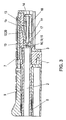
- FIG. 3 is a longitudinal section through the closure system according to the invention in the locked state
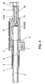
- FIG. 4 shows a longitudinal section corresponding to FIG. 3, but in unlocked condition with the closure moved backwards.
- the central part of the system is the running block 1, in which the barrel 2 is screwed in and thus fixed only at this screw-in point.
- the running block 1 Inserted between run 2 and run block 1 is still as a separate component a ramp 3.
- the cartridge is inserted into the chamber of the rigid barrel 2.
- This ramp 3 is a critical part of all self-loading weapon systems and usually part of the barrel.
- different projectile shapes also require different ramp shapes for a perfect feed, with which the exchangeable ramp 3 of the construction according to the invention is a clear advantage since correspondingly different ramps 3 can be used for the most varied projectile shapes.
- the connection between the closure 10 and barrel 2 is made via two lateral, along and parallel to the barrel 2 extending trapezoidal slide 4, the front ends are mounted in lateral projections 5a of a spring guide sleeve 5.
- These lateral projections 5a of the spring guide sleeve 5 are guided in longitudinal slots 6a of a front running cover 6, which, however, just like the spring guide sleeve 5 itself, does not touch the barrel 2.
- a cocking slide 7 and a slide catch lever 8 is also installed, and by the closing spring 9, which also surrounds the barrel 2 without contact, the closure 10 is acted upon in the direction of the rear end of the barrel 2 with the closing force.
- the closure 10 is provided with a push bottom 11 and is thereby held by a support bar 12 in the locked position that this support bar 12 against the running block (as will be explained in more detail below) is supported.
- the support bolt cooperates in the unlocked position with the movable delay block 13, whose rearward movement is damped by the delay spring 18 and limited by the baffle plate 14 of the closure 10.
- Also connected to the shutter 10 are known per se components such as Ausziehkralle 15 for the cartridge case, ejector 16 together with associated ejector spring 19 and cartridge holder 17.
- both trapezoidal slide 4 elongated cutouts 4a and in Laufblock 1 also side slots 1a and both sides of the longitudinal axis in the shutter 10 shots prepared for, in which alternately Ausziehkralle 15 and ejector 16 can be used.
- the support bar 12 is provided with supporting bar springs 20 acting on this position.
- the functioning of the closure system according to the invention during firing will be explained below with reference to FIGS. 3 and 4.
- the explosion pulse impinges on the barrel 2 facing the front of the closure 10. This is held by the support bar 12 but in its position, which is supported in the support bar nest 1b of the walking block 1.
- the deflected by the support bar 12 mainly in the tread block 1 force is on the opposite end of the barrel 2 support bar 12 on the one hand to an inclined plane of the support bolt nest 1b and at the same time, reduced by the geometry of the support bar 12, also on the inclined plane of the delay block 13 initiated.
- This force pushes the support bar 12 along the said inclined planes toward the shutter 10 and accelerates first the delay block 13, which slides so far back that the support bar 12 may also against the force of the support bolt spring (s) 20 can fold down and completely unlocked from the support bar nest 1b of the barrel block 1. In this position, the support bar 12 is then release the closure 10 and in turn can perform the opening movement to the rear.
- the delay block 13 is in turn delayed by the corresponding spring force in its movement by the shock spring 11, which in turn slides in a groove of the closure 10 and includes the delay spring 18, which is supported on the baffle plate 14.
- This delay must be sufficient for the projectile to leave the rigid barrel 2 at its forward end before the actual movement of opening the closure 10 commences. This can be easily ensured by a suitably designed delay spring 18 whose travel is only a few millimeters, but whose length is several centimeters.
- the closure 10 Only after this process is completed, the closure 10 begins to move against the force of the closing spring 9 to the rear.
- the closure 10 pulls on the trapezoidal slide 4 arranged on both sides, which in turn are connected to the spring guiding sleeve 5 and on which the closing spring 9 is supported, which in turn is supported with its other end on the running block 1.
- Neither the closing spring 9 nor the spring guide sleeve 5 touch the barrel 2 on its surface, whereby it can swing freely.
- the spring guide sleeve 5 is guided on its outer side by the running cover 6, which is preferably connected by means of bolts to the walking block 1 and centered by means of run 2, preferably via the lateral projections 5a in longitudinal slots 6a of the barrel cover 6.
- the comparatively to other pistols large diameter of the closing spring 9 makes it possible to make this very elastic and independent of caliber and laboratory ammunition.
- the cartridge case is held by the cartridge holder 17, the ejector 16 and the Ausziehkralle 15 and pulled out of the chamber of the rigid barrel 2.
- the ejector 16 mounted in the closure 10 abuts with its rear end at the rear end of the window frame of the window 1a in the walking block 1 and moves against the direction of movement of the closure 10 and against the spring force of the Ausstosserfeder 19 whose other end is supported on the cartridge holder 17, after front.
- the cartridge case is held on the periphery of the cartridge bottom by the Ausziehkralle 15 at the opposite end of the ejector 16 and thus ejected through the other window 1a of the barrel block 1 and the cutout 4a of the trapezoidal slide 4.
- the carriage catcher 8 can preferably be pushed upwardly by the magazine spring and latched into a corresponding recess on the underside of the trapezoidal carriage 4, thus interrupting the repeating action, i. the shutter 10 together with its side parts remains in the rearmost position and a new full magazine can be introduced and by manual depression of the carriage catch lever 8 of the interrupted repeating process is continued.
- a slide catch lever 8 may be provided on both sides and connected to an axle. When changing the ejection side of the slide catch lever 8 would be needed anyway on the "other" side.
- the closure 10 begins to move forward again due to the force of the compressed closure spring 9 together with all its secondary parts.
- the front end of the bottom 11 bumps (between the magazine lips) on the upper end of the cartridge bottom and pushes the next cartridge in front of him from the magazine.
- the cartridge is inserted into the chamber of the rigid barrel 2.
- This ramp 3 could also be an integral part of the barrel 2 as usual.
- different projectile shapes also require different ramp shapes for a perfect feed, so that a separate, exchangeable ramp 3 is a clear advantage in the sense of highest flexibility and adaptability of the weapon.
- the ejector 16 retracts due to the force of the compressed Ausstosserfeder 19 back to its original position in the closure 10.
- the support bar 12 preferably supported by the support bar spring (s) 20, in any case begins by the oblique slid also forward Level of the delay block 13, to lock.
- the shock bottom 11 moves due to the force of the compressed delay spring 18 now under the cartridge already in the cartridge chamber further forward.
- the cartridge is now from four sides - centered above by the cartridge holder 17, right and left by the preferably designed as a sprung part Ausziehkralle 15 and the ejector 16 and down through the now protruding part of the shock pad 11 - with respect to their position to the closure 10 , This ensures that the firing pin will hit the center of the cartridge where the primer is located.
- one or more recess may be provided which one or more fuses for (not shown) handle (weapon base) are now only to disable, to premature and / or unintentional firing of the weapon to prevent.
- the weapon is now ready to fire again, the cartridge in the barrel, unlocked.
- the closing spring 9 is designed to be relatively soft and elastic compared to weapons of today's design, since the mass of moving parts of the system according to the invention only about 50% of the mass of conventional weapons makes up (240g compared to the 480g mass of moving parts of the Colt Government M1911). From here the process is the same as described above.
- the locking surfaces are generously sized, and due to the power conditions of the tread block 1 could be even in the lightest copies, for example, made of aluminum.
- the cocking slide 7 and the cover 6 can be made of lightweight materials, such as Dur aluminum, aluminum or even plastic.
Landscapes
- Engineering & Computer Science (AREA)
- General Engineering & Computer Science (AREA)
- Toys (AREA)
- Portable Nailing Machines And Staplers (AREA)
- Orthopedics, Nursing, And Contraception (AREA)
- Input Circuits Of Receivers And Coupling Of Receivers And Audio Equipment (AREA)
- Materials For Medical Uses (AREA)
- Valve Device For Special Equipments (AREA)
- Seal Device For Vehicle (AREA)
- Glass Compositions (AREA)
Claims (7)
- Système de culasse pour une arme à feu, avec une culasse pouvant être verrouillée par au moins un élément de verrouillage dans son déplacement dans le bloc canon, qui est sollicitée par un ressort de fermeture au moyen d'au moins un élément de liaison sollicité en traction contre l'extrémité arrière du canon, le canon (2) est immobile et le ressort de culasse (9) entoure le canon (2) rigide, le ressort de fermeture (9) s'appuyant sur l'extrémité arrière du canon (2) et une temporisation purement mécanique étant insérée uniquement entre la culasse (10) et le ressort de culasse (9), caractérisé en ce que la temporisation mécanique est formée par un ressort de temporisation (18), un verrou de support (12) et un bloc de temporisation (13), le verrou de support (12) s'appuyant dans une cavité de verrou de support (1b) du bloc canon (1), dont le côté arrière forme avec le côté avant du bloc de temporisation (13) un logement en V, ouvert en direction du canon (2), et le bloc de temporisation (13) étant sollicité par le ressort de temporisation (18) s'appuyant sur la culasse (10) en direction du canon (2).
- Système de culasse selon la revendication 1, caractérisé en ce que le ressort de temporisation (18) s'appuie sur une plaque de rebondissement (14) sur le côté arrière de la culasse (10), laquelle est située à faible distance du bloc de temporisation (13) lorsque la culasse est fermée.
- Système de culasse selon la revendication 1 ou 2, caractérisé en ce que la distance entre la plaque de rebondissement (14) et la culasse (10) et le bloc de temporisation (13), qui définit la course de ressort de temporisation (18), est plus petite par rapport à la longueur du ressort de temporisation (18).
- Système de culasse selon l'une quelconque des revendications 1 à 3, caractérisé en ce que, comme liaison de la culasse (10) et du ressort de culasse (9), il est prévu deux coulisseaux trapézoïdaux (4) comme éléments de traction latéraux sur lesquels sont prévus des côtés opposés du canon (2).
- Système de culasse selon la revendication 4, caractérisé en ce que dans la position longitudinale le long du canon (2) et du bloc canon (1), à la hauteur de la position de la cartouche, dans au moins un coulisseau trapézoïdal (4), de préférence dans les deux coulisseaux trapézoïdaux, sont prévues des découpes (4a) pour l'éjection des cartouches.
- Système de culasse selon la revendication 5, caractérisé en ce que sur la culasse (10) sont formés deux logements réciproquement opposés pour l'éjecteur (16).
- Système de culasse selon la revendication 5, caractérisé en ce que les coulisseaux trapézoïdaux (4) s'appliquent avec leur extrémité opposée à la culasse (10) sur une douille de guidage de ressort représentant le second serrage du ressort de fermeture (5), qui est espacée de tout côté du canon (2) de l'arme, de même que le ressort de culasse (9).
Applications Claiming Priority (3)
| Application Number | Priority Date | Filing Date | Title |
|---|---|---|---|
| AT1322003 | 2003-01-29 | ||
| AT0013203A AT412743B (de) | 2003-01-29 | 2003-01-29 | Verschlusssystem für eine feuerwaffe |
| PCT/AT2004/000020 WO2004068056A1 (fr) | 2003-01-29 | 2004-01-21 | Système de culasse pour arme à feu |
Publications (2)
| Publication Number | Publication Date |
|---|---|
| EP1588116A1 EP1588116A1 (fr) | 2005-10-26 |
| EP1588116B1 true EP1588116B1 (fr) | 2007-04-25 |
Family
ID=32777511
Family Applications (1)
| Application Number | Title | Priority Date | Filing Date |
|---|---|---|---|
| EP04703720A Expired - Lifetime EP1588116B1 (fr) | 2003-01-29 | 2004-01-21 | Systeme de culasse pour arme a feu |
Country Status (5)
| Country | Link |
|---|---|
| US (1) | US7287456B2 (fr) |
| EP (1) | EP1588116B1 (fr) |
| AT (2) | AT412743B (fr) |
| DE (1) | DE502004003607D1 (fr) |
| WO (1) | WO2004068056A1 (fr) |
Families Citing this family (25)
| Publication number | Priority date | Publication date | Assignee | Title |
|---|---|---|---|---|
| AT413603B (de) * | 2004-03-04 | 2006-04-15 | Gen Headquarters Of The Armed | Pistole mit halbstarrer verriegelung |
| US8006609B2 (en) * | 2007-09-28 | 2011-08-30 | Sturm, Ruger & Company, Inc. | Slide catch-ejector assembly for firearm |
| US7726230B1 (en) | 2008-01-08 | 2010-06-01 | Saim Alper Erdem | Semiautomatic pistol |
| DE102008027709A1 (de) * | 2008-06-11 | 2009-12-17 | Blaser Finanzholding Gmbh | Verschluss für ein Repetiergewehr und Systemkasten für einen derartigen Verschluss |
| DE202008007768U1 (de) * | 2008-06-11 | 2009-10-22 | Blaser Finanzholding Gmbh | Verschluss für ein Repetiergewehr und Lauf für einen derartigen Verschluss |
| US20100307042A1 (en) | 2009-06-05 | 2010-12-09 | Michael Brent Jarboe | Modular firearm stock system |
| AT510442B1 (de) | 2011-08-24 | 2012-04-15 | Wilhelm Bubits | Pistole mit verriegelung durch verriegelungskörper |
| US8844185B2 (en) | 2012-08-27 | 2014-09-30 | Ra Brands, L.L.C. | Buttstock assembly |
| USD704294S1 (en) | 2012-09-19 | 2014-05-06 | Ra Brands, L.L.C. | Buttstock |
| US9151552B2 (en) | 2013-03-15 | 2015-10-06 | Christos Stratis Gryparis | Lock interface insert for machine gun bolt assembly |
| US20140338522A1 (en) * | 2013-05-14 | 2014-11-20 | Norman Anthony Bellione | Semi-Automatic Pistol |
| AT513605B1 (de) * | 2013-06-21 | 2014-06-15 | Christian Kada | Umrüstbausatz für eine Schusswaffe sowie Verfahren zum Umrüsten einer Schusswaffe |
| US9383154B2 (en) | 2013-12-12 | 2016-07-05 | Ra Brands, L.L.C. | Gas vent for firearm |
| US9562730B2 (en) | 2014-01-13 | 2017-02-07 | Ra Brands, L.L.C. | Replaceable feed ramp |
| US10563947B2 (en) | 2016-11-10 | 2020-02-18 | Michael SAWICKI | Training magazine and safety system for firearms |
| US10203173B2 (en) | 2017-04-22 | 2019-02-12 | Jameson S. Ellis | Barrel locking mechanism for a firearm |
| EP3698095B1 (fr) | 2017-10-20 | 2023-08-16 | Sturm, Ruger & Company, Inc. | Arme a feu avec mécanisme inertiel |
| WO2019113591A1 (fr) * | 2017-12-08 | 2019-06-13 | James Eric Mcmillan | Ensemble canon de fusil concentrique |
| US20200141682A1 (en) * | 2017-12-08 | 2020-05-07 | James Eric McMillan | Concentric rifle barrel assembly |
| US11231243B2 (en) | 2020-02-24 | 2022-01-25 | Jameson S. Ellis | Recoil spring assembly for a firearm, firearm, and method |
| US11391529B2 (en) | 2020-03-04 | 2022-07-19 | Jameson S. Ellis | Striker assembly and associated firearm and method |
| CZ309594B6 (cs) * | 2022-03-03 | 2023-05-03 | Česká Zbrojovka A.S. | Palná zbraň |
| CZ2022101A3 (cs) * | 2022-03-07 | 2023-04-19 | Pavel Blata | Brzdný mechanismus pistole |
| US12092416B1 (en) * | 2022-03-16 | 2024-09-17 | Theodore R. Schumacher | Delayed blowback device |
| US20250334360A1 (en) * | 2024-04-30 | 2025-10-30 | Geoffrey Louis Ader | Firearm piston and fire control mechanism |
Family Cites Families (19)
| Publication number | Priority date | Publication date | Assignee | Title |
|---|---|---|---|---|
| US956431A (en) * | 1908-06-01 | 1910-04-26 | Rheinische Metallw & Maschf | Automatic firearm. |
| US1138376A (en) * | 1912-10-25 | 1915-05-04 | Alva C Washburne | Firearm. |
| GB133695A (fr) * | 1915-07-30 | |||
| US1840054A (en) * | 1928-11-23 | 1932-01-05 | Alva C Washburne | Firearm |
| US2535156A (en) * | 1948-04-08 | 1950-12-26 | Colt S Mfg Company | Semiautomatic firearm with trigger operated cocking mechanism |
| US2919630A (en) * | 1957-06-14 | 1960-01-05 | Willard J Hoyt | Firearm with breech block retarding means |
| CH432298A (de) * | 1965-03-10 | 1967-03-15 | Oerlikon Buehrle Holding Ag | Selbsttätige Feuerwaffe |
| US3755948A (en) * | 1970-06-24 | 1973-09-04 | J Heinicke | Tubular firearm |
| US4232583A (en) * | 1978-12-14 | 1980-11-11 | Harrison Donald G | Firearm with recoil movement delaying mechanism |
| DE2914396A1 (de) * | 1979-04-10 | 1980-10-30 | Waffentechnik Gmbh | Verriegeltes verschlussystem fuer handfeuerwaffen |
| DE3109730A1 (de) * | 1981-03-13 | 1982-11-25 | Technica Entwicklungsgesellschaft mbH & Co KG, 2418 Ratzeburg | Selbstladepistole |
| US4579037A (en) * | 1984-02-13 | 1986-04-01 | Weapon Technology Systems R & D, Ltd. | Machine pistol with retarded blowback |
| AT393028B (de) * | 1986-04-08 | 1991-07-25 | Maximilian Vojta | Gasentnahmesystem fuer eine feuerwaffe |
| AT388238B (de) * | 1986-12-19 | 1989-05-26 | Steyr Daimler Puch Ag | Schusswaffe |
| AT400197B (de) * | 1990-03-15 | 1995-10-25 | Vojta Maximilian | System zum wechseln des laufes einer feuerwaffe |
| IT1286568B1 (it) * | 1996-03-13 | 1998-07-15 | Gianni Zanieri | Meccanismo di chiusura per armi automatiche o semi automatiche |
| US6109160A (en) * | 1996-03-13 | 2000-08-29 | Zanieri; Gianni | Breechblock for automatic or semi-automatic weapons |
| AUPQ598700A0 (en) * | 2000-03-02 | 2000-05-18 | Vader Pty Ltd | Weapon |
| US6993864B1 (en) * | 2003-02-11 | 2006-02-07 | Smith & Wesson Corp. | Locking block for compact semi-automatic pistols |
-
2003
- 2003-01-29 AT AT0013203A patent/AT412743B/de not_active IP Right Cessation
-
2004
- 2004-01-21 AT AT04703720T patent/ATE360793T1/de not_active IP Right Cessation
- 2004-01-21 WO PCT/AT2004/000020 patent/WO2004068056A1/fr not_active Ceased
- 2004-01-21 DE DE502004003607T patent/DE502004003607D1/de not_active Expired - Lifetime
- 2004-01-21 EP EP04703720A patent/EP1588116B1/fr not_active Expired - Lifetime
-
2005
- 2005-07-26 US US11/189,283 patent/US7287456B2/en not_active Expired - Lifetime
Non-Patent Citations (1)
| Title |
|---|
| None * |
Also Published As
| Publication number | Publication date |
|---|---|
| EP1588116A1 (fr) | 2005-10-26 |
| ATA1322003A (de) | 2004-11-15 |
| WO2004068056A1 (fr) | 2004-08-12 |
| US20070012170A1 (en) | 2007-01-18 |
| US7287456B2 (en) | 2007-10-30 |
| DE502004003607D1 (de) | 2007-06-06 |
| AT412743B (de) | 2005-06-27 |
| ATE360793T1 (de) | 2007-05-15 |
Similar Documents
| Publication | Publication Date | Title |
|---|---|---|
| AT412743B (de) | Verschlusssystem für eine feuerwaffe | |
| DE69512005T2 (de) | Schusswaffe | |
| DE4341131C1 (de) | Schußwaffe mit Rückstoßabpufferung, insbesondere Faustfeuerwaffe | |
| EP0505917B1 (fr) | Arme à feu, notamment arme de poing | |
| EP2157393B1 (fr) | Pistolet automatique | |
| EP4290173B1 (fr) | Carcasse pour une arme à feu à chargement automatique, ainsi que arme à feu à chargement automatique équipée d'une telle carcasse | |
| DE69802079T2 (de) | Automatische feuerwaffe | |
| EP3372942B1 (fr) | Arme à feu de poing à chargement automatique verrouillable | |
| DE102014102672B4 (de) | Feuerwaffe, insbesondere Handfeuerwaffe, sowie Verfahren zur Herstellung einer Feuerwaffe | |
| DE19529483C1 (de) | Selbstladegewehr mit Schwenklauf | |
| EP3591329A1 (fr) | Dispositif d'arrêt de culasse pourvu de dispositif de blocage d'une arme à feu à chargement automatique ainsi que poignée d'arme équipée d'un tel dispositif d'arrêt de verrouillage et boîtier d'arme | |
| DE102004021952B3 (de) | Selbstlade-Handfeuerwaffe mit beschleunigtem Verschlußträger | |
| WO1998054532A2 (fr) | Pistolet mitrailleur, ensemble de transformation pour pistolet mitrailleur avec verrouillage de la culasse, et arme pouvant etre au choix un pistolet mitrailleur avec ou sans verrouillage de la culasse | |
| DE102020004940B4 (de) | Verschlussvorrichtung für eine Handfeuerwaffe, Handfeuerwaffe mit einer Verschlussvorrichtung | |
| EP4370857B1 (fr) | Arme à feu | |
| EP1535012B1 (fr) | Arme a feu de poing a culasse verrouillee | |
| AT393028B (de) | Gasentnahmesystem fuer eine feuerwaffe | |
| DE4035860A1 (de) | Automatische handfeuerwaffe mit starr verriegeltem verschluss fuer huelsenlose munition | |
| DE69816722T2 (de) | Übungslauf mit einer Geschosszuführrampe für Feuerwaffen | |
| DE102023000143B4 (de) | Handfeuerwaffe und Verfahren zum Betreiben einer Handfeuerwaffe | |
| DE1166052B (de) | Einsatzgeraet mit Einstecklauf zum Verschiessen von Kleinkaliber-Munition durch automatische Handfeuerwaffen, insbesondere Sturmgewehre mit Hammerzuendung | |
| DE69714592T2 (de) | Rohrpositionierungsmechanismus für automatische handfeuerwaffen | |
| EP4403868A1 (fr) | Arme à feu portative et procédé de fonctionnement d'une arme à feu portative | |
| EP0800050A1 (fr) | Arme à fonction multiple | |
| DE102021004902A1 (de) | Schließfedereinrichtung für eine Handfeuerwaffe, Handfeuerwaffe mit einer Schließfedereinrichtung |
Legal Events
| Date | Code | Title | Description |
|---|---|---|---|
| PUAI | Public reference made under article 153(3) epc to a published international application that has entered the european phase |
Free format text: ORIGINAL CODE: 0009012 |
|
| 17P | Request for examination filed |
Effective date: 20050714 |
|
| AK | Designated contracting states |
Kind code of ref document: A1 Designated state(s): AT BE BG CH CY CZ DE DK EE ES FI FR GB GR HU IE IT LI LU MC NL PT RO SE SI SK TR |
|
| AX | Request for extension of the european patent |
Extension state: AL LT LV MK |
|
| DAX | Request for extension of the european patent (deleted) | ||
| GRAP | Despatch of communication of intention to grant a patent |
Free format text: ORIGINAL CODE: EPIDOSNIGR1 |
|
| GRAS | Grant fee paid |
Free format text: ORIGINAL CODE: EPIDOSNIGR3 |
|
| GRAA | (expected) grant |
Free format text: ORIGINAL CODE: 0009210 |
|
| AK | Designated contracting states |
Kind code of ref document: B1 Designated state(s): AT BE BG CH CY CZ DE DK EE ES FI FR GB GR HU IE IT LI LU MC NL PT RO SE SI SK TR |
|
| PG25 | Lapsed in a contracting state [announced via postgrant information from national office to epo] |
Ref country code: FI Free format text: LAPSE BECAUSE OF FAILURE TO SUBMIT A TRANSLATION OF THE DESCRIPTION OR TO PAY THE FEE WITHIN THE PRESCRIBED TIME-LIMIT Effective date: 20070425 |
|
| REG | Reference to a national code |
Ref country code: GB Ref legal event code: FG4D Free format text: NOT ENGLISH |
|
| GBT | Gb: translation of ep patent filed (gb section 77(6)(a)/1977) |
Effective date: 20070503 |
|
| REG | Reference to a national code |
Ref country code: IE Ref legal event code: FG4D Free format text: LANGUAGE OF EP DOCUMENT: GERMAN |
|
| REG | Reference to a national code |
Ref country code: CH Ref legal event code: EP |
|
| REF | Corresponds to: |
Ref document number: 502004003607 Country of ref document: DE Date of ref document: 20070606 Kind code of ref document: P |
|
| PG25 | Lapsed in a contracting state [announced via postgrant information from national office to epo] |
Ref country code: SE Free format text: LAPSE BECAUSE OF FAILURE TO SUBMIT A TRANSLATION OF THE DESCRIPTION OR TO PAY THE FEE WITHIN THE PRESCRIBED TIME-LIMIT Effective date: 20070725 |
|
| PG25 | Lapsed in a contracting state [announced via postgrant information from national office to epo] |
Ref country code: ES Free format text: LAPSE BECAUSE OF FAILURE TO SUBMIT A TRANSLATION OF THE DESCRIPTION OR TO PAY THE FEE WITHIN THE PRESCRIBED TIME-LIMIT Effective date: 20070805 |
|
| ET | Fr: translation filed | ||
| PG25 | Lapsed in a contracting state [announced via postgrant information from national office to epo] |
Ref country code: PT Free format text: LAPSE BECAUSE OF FAILURE TO SUBMIT A TRANSLATION OF THE DESCRIPTION OR TO PAY THE FEE WITHIN THE PRESCRIBED TIME-LIMIT Effective date: 20070925 |
|
| NLV1 | Nl: lapsed or annulled due to failure to fulfill the requirements of art. 29p and 29m of the patents act | ||
| REG | Reference to a national code |
Ref country code: IE Ref legal event code: FD4D |
|
| PG25 | Lapsed in a contracting state [announced via postgrant information from national office to epo] |
Ref country code: SI Free format text: LAPSE BECAUSE OF FAILURE TO SUBMIT A TRANSLATION OF THE DESCRIPTION OR TO PAY THE FEE WITHIN THE PRESCRIBED TIME-LIMIT Effective date: 20070425 Ref country code: DK Free format text: LAPSE BECAUSE OF FAILURE TO SUBMIT A TRANSLATION OF THE DESCRIPTION OR TO PAY THE FEE WITHIN THE PRESCRIBED TIME-LIMIT Effective date: 20070425 Ref country code: NL Free format text: LAPSE BECAUSE OF FAILURE TO SUBMIT A TRANSLATION OF THE DESCRIPTION OR TO PAY THE FEE WITHIN THE PRESCRIBED TIME-LIMIT Effective date: 20070425 Ref country code: CZ Free format text: LAPSE BECAUSE OF FAILURE TO SUBMIT A TRANSLATION OF THE DESCRIPTION OR TO PAY THE FEE WITHIN THE PRESCRIBED TIME-LIMIT Effective date: 20070425 Ref country code: BG Free format text: LAPSE BECAUSE OF FAILURE TO SUBMIT A TRANSLATION OF THE DESCRIPTION OR TO PAY THE FEE WITHIN THE PRESCRIBED TIME-LIMIT Effective date: 20070725 Ref country code: IE Free format text: LAPSE BECAUSE OF FAILURE TO SUBMIT A TRANSLATION OF THE DESCRIPTION OR TO PAY THE FEE WITHIN THE PRESCRIBED TIME-LIMIT Effective date: 20070425 |
|
| PG25 | Lapsed in a contracting state [announced via postgrant information from national office to epo] |
Ref country code: SK Free format text: LAPSE BECAUSE OF FAILURE TO SUBMIT A TRANSLATION OF THE DESCRIPTION OR TO PAY THE FEE WITHIN THE PRESCRIBED TIME-LIMIT Effective date: 20070425 |
|
| PLBE | No opposition filed within time limit |
Free format text: ORIGINAL CODE: 0009261 |
|
| STAA | Information on the status of an ep patent application or granted ep patent |
Free format text: STATUS: NO OPPOSITION FILED WITHIN TIME LIMIT |
|
| 26N | No opposition filed |
Effective date: 20080128 |
|
| PG25 | Lapsed in a contracting state [announced via postgrant information from national office to epo] |
Ref country code: GR Free format text: LAPSE BECAUSE OF FAILURE TO SUBMIT A TRANSLATION OF THE DESCRIPTION OR TO PAY THE FEE WITHIN THE PRESCRIBED TIME-LIMIT Effective date: 20070726 |
|
| PG25 | Lapsed in a contracting state [announced via postgrant information from national office to epo] |
Ref country code: RO Free format text: LAPSE BECAUSE OF FAILURE TO SUBMIT A TRANSLATION OF THE DESCRIPTION OR TO PAY THE FEE WITHIN THE PRESCRIBED TIME-LIMIT Effective date: 20070425 |
|
| BERE | Be: lapsed |
Owner name: SPIELBERGER, PETER Effective date: 20080131 |
|
| PG25 | Lapsed in a contracting state [announced via postgrant information from national office to epo] |
Ref country code: MC Free format text: LAPSE BECAUSE OF NON-PAYMENT OF DUE FEES Effective date: 20080131 |
|
| PGFP | Annual fee paid to national office [announced via postgrant information from national office to epo] |
Ref country code: AT Payment date: 20080617 Year of fee payment: 5 |
|
| REG | Reference to a national code |
Ref country code: CH Ref legal event code: PL |
|
| PG25 | Lapsed in a contracting state [announced via postgrant information from national office to epo] |
Ref country code: CH Free format text: LAPSE BECAUSE OF NON-PAYMENT OF DUE FEES Effective date: 20080131 Ref country code: LI Free format text: LAPSE BECAUSE OF NON-PAYMENT OF DUE FEES Effective date: 20080131 |
|
| PG25 | Lapsed in a contracting state [announced via postgrant information from national office to epo] |
Ref country code: EE Free format text: LAPSE BECAUSE OF FAILURE TO SUBMIT A TRANSLATION OF THE DESCRIPTION OR TO PAY THE FEE WITHIN THE PRESCRIBED TIME-LIMIT Effective date: 20070425 |
|
| PG25 | Lapsed in a contracting state [announced via postgrant information from national office to epo] |
Ref country code: BE Free format text: LAPSE BECAUSE OF NON-PAYMENT OF DUE FEES Effective date: 20080131 |
|
| PG25 | Lapsed in a contracting state [announced via postgrant information from national office to epo] |
Ref country code: CY Free format text: LAPSE BECAUSE OF FAILURE TO SUBMIT A TRANSLATION OF THE DESCRIPTION OR TO PAY THE FEE WITHIN THE PRESCRIBED TIME-LIMIT Effective date: 20070425 |
|
| PG25 | Lapsed in a contracting state [announced via postgrant information from national office to epo] |
Ref country code: AT Free format text: LAPSE BECAUSE OF NON-PAYMENT OF DUE FEES Effective date: 20090121 |
|
| PG25 | Lapsed in a contracting state [announced via postgrant information from national office to epo] |
Ref country code: HU Free format text: LAPSE BECAUSE OF FAILURE TO SUBMIT A TRANSLATION OF THE DESCRIPTION OR TO PAY THE FEE WITHIN THE PRESCRIBED TIME-LIMIT Effective date: 20071026 Ref country code: LU Free format text: LAPSE BECAUSE OF NON-PAYMENT OF DUE FEES Effective date: 20080121 |
|
| PG25 | Lapsed in a contracting state [announced via postgrant information from national office to epo] |
Ref country code: TR Free format text: LAPSE BECAUSE OF FAILURE TO SUBMIT A TRANSLATION OF THE DESCRIPTION OR TO PAY THE FEE WITHIN THE PRESCRIBED TIME-LIMIT Effective date: 20070425 |
|
| PGFP | Annual fee paid to national office [announced via postgrant information from national office to epo] |
Ref country code: FR Payment date: 20120214 Year of fee payment: 9 |
|
| PGFP | Annual fee paid to national office [announced via postgrant information from national office to epo] |
Ref country code: DE Payment date: 20120214 Year of fee payment: 9 |
|
| PGFP | Annual fee paid to national office [announced via postgrant information from national office to epo] |
Ref country code: GB Payment date: 20120130 Year of fee payment: 9 Ref country code: IT Payment date: 20120131 Year of fee payment: 9 |
|
| GBPC | Gb: european patent ceased through non-payment of renewal fee |
Effective date: 20130121 |
|
| REG | Reference to a national code |
Ref country code: FR Ref legal event code: ST Effective date: 20130930 |
|
| PG25 | Lapsed in a contracting state [announced via postgrant information from national office to epo] |
Ref country code: DE Free format text: LAPSE BECAUSE OF NON-PAYMENT OF DUE FEES Effective date: 20130801 |
|
| REG | Reference to a national code |
Ref country code: DE Ref legal event code: R119 Ref document number: 502004003607 Country of ref document: DE Effective date: 20130801 |
|
| PG25 | Lapsed in a contracting state [announced via postgrant information from national office to epo] |
Ref country code: FR Free format text: LAPSE BECAUSE OF NON-PAYMENT OF DUE FEES Effective date: 20130131 Ref country code: GB Free format text: LAPSE BECAUSE OF NON-PAYMENT OF DUE FEES Effective date: 20130121 |
|
| PG25 | Lapsed in a contracting state [announced via postgrant information from national office to epo] |
Ref country code: IT Free format text: LAPSE BECAUSE OF NON-PAYMENT OF DUE FEES Effective date: 20130121 |