EP1587343A2 - Hörgerät - Google Patents
Hörgerät Download PDFInfo
- Publication number
- EP1587343A2 EP1587343A2 EP05102267A EP05102267A EP1587343A2 EP 1587343 A2 EP1587343 A2 EP 1587343A2 EP 05102267 A EP05102267 A EP 05102267A EP 05102267 A EP05102267 A EP 05102267A EP 1587343 A2 EP1587343 A2 EP 1587343A2
- Authority
- EP
- European Patent Office
- Prior art keywords
- housing
- hearing aid
- antenna
- conductive layer
- coil
- Prior art date
- Legal status (The legal status is an assumption and is not a legal conclusion. Google has not performed a legal analysis and makes no representation as to the accuracy of the status listed.)
- Granted
Links
Images
Classifications
-
- H—ELECTRICITY
- H04—ELECTRIC COMMUNICATION TECHNIQUE
- H04R—LOUDSPEAKERS, MICROPHONES, GRAMOPHONE PICK-UPS OR LIKE ACOUSTIC ELECTROMECHANICAL TRANSDUCERS; ELECTRIC HEARING AIDS; PUBLIC ADDRESS SYSTEMS
- H04R25/00—Electric hearing aids
- H04R25/55—Electric hearing aids using an external connection, either wireless or wired
- H04R25/554—Electric hearing aids using an external connection, either wireless or wired using a wireless connection, e.g. between microphone and amplifier or using Tcoils
-
- H—ELECTRICITY
- H01—ELECTRIC ELEMENTS
- H01Q—ANTENNAS, i.e. RADIO AERIALS
- H01Q1/00—Details of, or arrangements associated with, antennas
- H01Q1/27—Adaptation for use in or on movable bodies
- H01Q1/273—Adaptation for carrying or wearing by persons or animals
-
- H—ELECTRICITY
- H04—ELECTRIC COMMUNICATION TECHNIQUE
- H04R—LOUDSPEAKERS, MICROPHONES, GRAMOPHONE PICK-UPS OR LIKE ACOUSTIC ELECTROMECHANICAL TRANSDUCERS; ELECTRIC HEARING AIDS; PUBLIC ADDRESS SYSTEMS
- H04R2225/00—Details of deaf aids covered by H04R25/00, not provided for in any of its subgroups
- H04R2225/51—Aspects of antennas or their circuitry in or for hearing aids
Definitions
- the present invention relates to a hearing aid with a housing and an RF antenna and / or electrical coil for electromagnetic energy and / or data transmission.
- the miniaturization or equipment of hearing aids inter alia by the dimensions of, for example, telecoils, battery charging coils or HF antennas for wireless communication limited.
- HF antennas are used integrated into the circuit boards of the hearing aid electronics are.
- Such printed on printed circuit boards antennas are for example from the WHITE PAPER " ⁇ / 4 printed monopole antenna for 2.45GHz "by Nordic VLSI ASA, February 2003.
- a disadvantage of the known coils is that they are still need a relatively large amount of installation space.
- the object of the present invention is therefore to the necessary installation space for coils of hearing aids on to downsize.
- this object is achieved by a hearing aid with a housing and an RF antenna and / or electrical Coil for electromagnetic energy and / or data transmission, wherein the RF antenna and / or the electrical coil in Material of the housing or on the housing as electrically conductive Layer is formed.
- the electrically conductive layer is through a Metallization, which was subsequently structured, formed.
- the metallization process of the hearing aid housing be very simple.
- the electrically conductive Layer as a structured metal layer on the interior or Apply outside of the housing. This can be an under Circumstances consuming structuring process can be avoided.
- Another variant for making an antenna or Coil in the form of an electrically conductive layer is pour the electrically conductive layer into the housing.
- the coil or antenna is safe against mechanical Influences protected from the outside.
- the electrically conductive layer may further consist of a consist of conductive plastic material. This can help with the Production of the coil or antenna the usual plastic manufacturing processes Find use.
- the antenna or coil may further be formed by that in or on the housing a plurality of layers of the electrically conductive Layer are arranged one above the other. In this way allows the spatial conditions even further especially when high inductance is required.
- the coil may also be considered as the housing about its longitudinal axis be formed circumferential conductor.
- this has the advantage that such, in parallel to the auricle aligned coil well as a telecoil can be used.
- the housing encircling Coil can also be used when the case is split longitudinally.
- any other conductor structure can be over both housing halves extend.
- a in any Form structured conductor applied to the hearing aid housing is preferably done on the inside of the Hearing aid housing to damage the conductor structure by to avoid external influences.
- the ladder structure can also be mounted on the outside of the hearing aid housing, it is then recommended to have a protective layer over it apply.
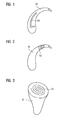
- FIG. 1 An example of an invention formed on the hearing aid housing RF antenna is shown in FIG.
- the L-shaped HF Antenna HA is a metal layer on the BTE hearing aid housing HG angry.
- the RF antenna HA as a preformed film formation on the HG hearing aid housing applied or by subsequent Structuring a metallization of the hearing aid housing HG educated.
- the RF antenna HA as already mentioned, as a conductive plastic layer during injection molding the hearing aid housing HG formed in the desired shape become.
- FIG. 1 Another embodiment of a hearing aid according to the invention is shown in FIG.
- the coil shown there SU has a helical character and turns around it Housing, which is also in this FIG 2 as a BTE hearing aid housing HG is shown.
- the coil SU is in a housing section formed and the axis of the coil SU corresponds to the Longitudinal axis of this housing section.
- FIG 3 A third embodiment of the present invention is disclosed in FIG 3 outlines.
- a spiral-shaped antenna SI is on the outwardly facing side of an IDO hearing aid housing IG appropriate.
- This hearing aid housing IG could but also, for example with a coil-shaped as shown in FIG Antenna equipped in the conical housing area be.
- a BTE case with a be provided spiral antenna is disclosed in FIG 3 outlines.
- the by the conductor layer generated device to the respective application be optimally adapted. This can be the profit, the directivity and the impedance in corresponding Influence way.
- several layers of Conductor layer superimposed within the shell layer be used to use the housing material as a dielectric.
Landscapes
- Engineering & Computer Science (AREA)
- Computer Networks & Wireless Communication (AREA)
- Signal Processing (AREA)
- General Health & Medical Sciences (AREA)
- Neurosurgery (AREA)
- Otolaryngology (AREA)
- Physics & Mathematics (AREA)
- Acoustics & Sound (AREA)
- Health & Medical Sciences (AREA)
- Support Of Aerials (AREA)
- Finger-Pressure Massage (AREA)
- Details Of Aerials (AREA)
- Adornments (AREA)
- Transmitters (AREA)
- Variable-Direction Aerials And Aerial Arrays (AREA)
- Structure Of Receivers (AREA)
Abstract
Description
- FIG 1
- ein HdO-Hörgerät mit einer Antenne gemäß einer ersten Ausführungsform;
- FIG 2
- ein HdO-Hörgerät mit einer Antenne gemäß einer zweiten Ausführungsform; und
- FIG 3
- ein IdO-Hörgerät mit einer Antenne gemäß einer dritten Ausführungsform der vorliegenden Erfindung.
Claims (8)
- Hörgerät miteinem Gehäuse (HG, IG) undeiner HF-Antenne und/oder elektrischen Spule (HA, SI, SU) zur elektromagnetischen Energie- und/oder Datenübertragung,dadurch gekennzeichnet, dassdie HF-Antenne und/oder die elektrische Spule (HA, SI, SU) im Material des Gehäuses oder an dem Gehäuse (HG, IG) als elektrisch leitende Schicht ausgebildet ist.
- Hörgerät nach Anspruch 1, wobei die leitende Schicht durch eine Metallisierung, die nachträglich strukturiert wurde, gebildet ist.
- Hörgerät nach Anspruch 1, wobei die elektrisch leitende Schicht als strukturierte Metallschicht an der Innen- oder Außenseite des Gehäuses (HG, IG) aufgebracht ist.
- Hörgerät nach Anspruch 1, wobei die elektrisch leitende Schicht in das Gehäuse (HG, IG) eingegossen ist.
- Hörgerät nach Anspruch 1, wobei die elektrisch leitende Schicht aus einem leitenden Kunststoffmaterial besteht.
- Hörgerät nach einem der vorhergehenden Ansprüche, wobei in oder an dem Gehäuse (HG, IG) mehrere Lagen der elektrisch leitenden Schicht übereinander angeordnet sind.
- Hörgerät nach einem der vorhergehenden Ansprüche, wobei die Spule (SU) als ein einen Gehäuseabschnitt um dessen Längsachse umlaufender Leiter ausgebildet ist.
- Hörgerät nach Anspruch 7, wobei das Gehäuse längsgeteilt ist und an oder in jeder Gehäusehälfte ein Teil der Antennen- bzw. Spulenleiterschicht ausgebildet ist.
Applications Claiming Priority (2)
| Application Number | Priority Date | Filing Date | Title |
|---|---|---|---|
| DE102004017832 | 2004-04-13 | ||
| DE102004017832A DE102004017832B3 (de) | 2004-04-13 | 2004-04-13 | Hörgerät |
Publications (3)
| Publication Number | Publication Date |
|---|---|
| EP1587343A2 true EP1587343A2 (de) | 2005-10-19 |
| EP1587343A3 EP1587343A3 (de) | 2006-01-18 |
| EP1587343B1 EP1587343B1 (de) | 2008-05-14 |
Family
ID=34939030
Family Applications (1)
| Application Number | Title | Priority Date | Filing Date |
|---|---|---|---|
| EP05102267A Expired - Lifetime EP1587343B1 (de) | 2004-04-13 | 2005-03-22 | Hörgerät |
Country Status (8)
| Country | Link |
|---|---|
| US (1) | US20050244024A1 (de) |
| EP (1) | EP1587343B1 (de) |
| JP (1) | JP2005304038A (de) |
| CN (1) | CN1684548A (de) |
| AT (1) | ATE395802T1 (de) |
| AU (1) | AU2005201376B2 (de) |
| DE (2) | DE102004017832B3 (de) |
| DK (1) | DK1587343T3 (de) |
Cited By (12)
| Publication number | Priority date | Publication date | Assignee | Title |
|---|---|---|---|---|
| WO2008012355A1 (en) * | 2006-07-28 | 2008-01-31 | Siemens Audiologische Technik Gmbh | Antenna arrangement for hearing device applications |
| EP1915030A1 (de) * | 2006-10-16 | 2008-04-23 | Siemens Audiologische Technik GmbH | Hörgerät mit stromführendem Metallbügel |
| EP1959712A3 (de) * | 2007-02-16 | 2009-05-06 | Siemens Audiologische Technik GmbH | Hörvorrichtung mit Hörerkompensationsspule |
| WO2009112898A2 (en) | 2008-03-13 | 2009-09-17 | Sony Ericsson Mobile Communications Ab | Antenna for use in earphone and earphone with integrated antenna |
| US8098858B2 (en) | 2006-10-16 | 2012-01-17 | Siemens Audiologische Technik Gmbh | Hearing device with current-conducting metal arm |
| EP2725655A1 (de) * | 2010-10-12 | 2014-04-30 | GN Resound A/S | Antennensystem für ein Hörgerät |
| WO2014090419A1 (de) * | 2012-12-12 | 2014-06-19 | Siemens Medical Instruments Pte. Ltd. | Modulare antenne für hörgeräte |
| EP2835863A1 (de) | 2013-08-09 | 2015-02-11 | Oticon A/s | HF-Antenne und Hörgerät mit HF-Antenne |
| US9408552B2 (en) | 2009-07-02 | 2016-08-09 | Widex A/S | Ear plug with surface electrodes |
| EP3101918A3 (de) * | 2015-05-13 | 2017-04-05 | Sivantos Pte. Ltd. | Hörgerät |
| US9980062B2 (en) | 2012-12-12 | 2018-05-22 | Sivantos Pte. Ltd. | Hearing aid and method for producing a hearing aid |
| EP3352296A1 (de) * | 2010-10-12 | 2018-07-25 | GN Hearing A/S | Hörgerät mit einer antenne |
Families Citing this family (64)
| Publication number | Priority date | Publication date | Assignee | Title |
|---|---|---|---|---|
| US7593538B2 (en) | 2005-03-28 | 2009-09-22 | Starkey Laboratories, Inc. | Antennas for hearing aids |
| US8041066B2 (en) | 2007-01-03 | 2011-10-18 | Starkey Laboratories, Inc. | Wireless system for hearing communication devices providing wireless stereo reception modes |
| US9774961B2 (en) | 2005-06-05 | 2017-09-26 | Starkey Laboratories, Inc. | Hearing assistance device ear-to-ear communication using an intermediate device |
| DE102005046169A1 (de) * | 2005-09-27 | 2007-04-05 | Siemens Audiologische Technik Gmbh | Hörhilfegerät mit einer Antenne |
| US7548211B2 (en) | 2006-03-30 | 2009-06-16 | Phonak Ag | Wireless audio signal receiver device for a hearing instrument |
| DK2257080T3 (da) | 2006-03-30 | 2012-04-10 | Phonak Ag | Trådløs audiosignalmodtagerindretning for et høreapparat |
| US8208642B2 (en) | 2006-07-10 | 2012-06-26 | Starkey Laboratories, Inc. | Method and apparatus for a binaural hearing assistance system using monaural audio signals |
| US20080049945A1 (en) * | 2006-08-25 | 2008-02-28 | Phonak Ag | System for binaural hearing assistance |
| DE102006049470B4 (de) * | 2006-10-16 | 2011-06-22 | Siemens Audiologische Technik GmbH, 91058 | Hörgerät mit einer Montagevorrichtung für eine Komponente einer Hörvorrichtung und entsprechendes Verfahren |
| DE102007001537A1 (de) * | 2007-01-10 | 2008-07-17 | Siemens Audiologische Technik Gmbh | Influenzladevorrichtung und entsprechendes Verfahren |
| US8934984B2 (en) | 2007-05-31 | 2015-01-13 | Cochlear Limited | Behind-the-ear (BTE) prosthetic device with antenna |
| DK2076065T4 (en) * | 2007-12-27 | 2017-02-20 | Oticon As | Hearing aid and method for wireless reception and / or transmission of data |
| JP5252741B2 (ja) | 2008-02-04 | 2013-07-31 | パナソニック株式会社 | 耳かけ型補聴器 |
| US8867765B2 (en) | 2008-02-06 | 2014-10-21 | Starkey Laboratories, Inc. | Antenna used in conjunction with the conductors for an audio transducer |
| US8737658B2 (en) * | 2008-12-19 | 2014-05-27 | Starkey Laboratories, Inc. | Three dimensional substrate for hearing assistance devices |
| US10142747B2 (en) | 2008-12-19 | 2018-11-27 | Starkey Laboratories, Inc. | Three dimensional substrate for hearing assistance devices |
| US8565457B2 (en) | 2008-12-19 | 2013-10-22 | Starkey Laboratories, Inc. | Antennas for standard fit hearing assistance devices |
| US8699733B2 (en) | 2008-12-19 | 2014-04-15 | Starkey Laboratories, Inc. | Parallel antennas for standard fit hearing assistance devices |
| US8494197B2 (en) | 2008-12-19 | 2013-07-23 | Starkey Laboratories, Inc. | Antennas for custom fit hearing assistance devices |
| EP2229009B1 (de) * | 2009-03-09 | 2013-10-30 | Oticon A/S | Hörgerät |
| US9420385B2 (en) | 2009-12-21 | 2016-08-16 | Starkey Laboratories, Inc. | Low power intermittent messaging for hearing assistance devices |
| US9432780B2 (en) | 2010-07-03 | 2016-08-30 | Starkey Laboratories, Inc. | Multi-mode radio for hearing assistance devices |
| EP2628210B1 (de) | 2010-10-12 | 2019-01-09 | GN Hearing A/S | Hörgerät mit antennenvorrichtung |
| JP5660870B2 (ja) * | 2010-11-29 | 2015-01-28 | リオン株式会社 | 補聴器用送信コイル |
| US20130343586A1 (en) * | 2012-06-25 | 2013-12-26 | Gn Resound A/S | Hearing aid having a slot antenna |
| US8878735B2 (en) * | 2012-06-25 | 2014-11-04 | Gn Resound A/S | Antenna system for a wearable computing device |
| DK201270411A (en) | 2012-07-06 | 2014-01-07 | Gn Resound As | BTE hearing aid having two driven antennas |
| US9554219B2 (en) | 2012-07-06 | 2017-01-24 | Gn Resound A/S | BTE hearing aid having a balanced antenna |
| DK201270410A (en) | 2012-07-06 | 2014-01-07 | Gn Resound As | BTE hearing aid with an antenna partition plane |
| US20140023216A1 (en) * | 2012-07-17 | 2014-01-23 | Starkey Laboratories, Inc. | Hearing assistance device with wireless communication for on- and off- body accessories |
| US9374650B2 (en) * | 2012-07-17 | 2016-06-21 | Starkey Laboratories, Inc. | System and method for embedding conductive traces into hearing assistance device housings |
| US9237404B2 (en) | 2012-12-28 | 2016-01-12 | Gn Resound A/S | Dipole antenna for a hearing aid |
| US9414170B2 (en) * | 2012-12-28 | 2016-08-09 | Gn Resound A/S | Hearing aid having an adaptive antenna matching mechanism and a method for adaptively matching a hearing aid antenna |
| JP6513895B2 (ja) * | 2013-02-20 | 2019-05-15 | 日東電工株式会社 | 携帯機器及びその充電機器、携帯機器充電システム |
| DE102013210689B3 (de) | 2013-06-07 | 2014-10-02 | Siemens Medical Instruments Pte. Ltd. | Antenneneinrichtung für Hörinstrumente |
| US9191757B2 (en) * | 2013-07-11 | 2015-11-17 | Starkey Laboratories, Inc. | Hearing aid with inductively coupled electromagnetic resonator antenna |
| US10985447B2 (en) | 2013-08-02 | 2021-04-20 | Gn Hearing A/S | Antenna device |
| KR102092857B1 (ko) * | 2013-10-25 | 2020-03-25 | 삼성전자주식회사 | 청각 기기용 누설파 안테나 |
| US9883295B2 (en) | 2013-11-11 | 2018-01-30 | Gn Hearing A/S | Hearing aid with an antenna |
| US9686621B2 (en) | 2013-11-11 | 2017-06-20 | Gn Hearing A/S | Hearing aid with an antenna |
| US9237405B2 (en) | 2013-11-11 | 2016-01-12 | Gn Resound A/S | Hearing aid with an antenna |
| US9408003B2 (en) | 2013-11-11 | 2016-08-02 | Gn Resound A/S | Hearing aid with an antenna |
| US10595138B2 (en) | 2014-08-15 | 2020-03-17 | Gn Hearing A/S | Hearing aid with an antenna |
| US20160072337A1 (en) * | 2014-09-04 | 2016-03-10 | Samsung Electro-Mechanics Co., Ltd. | Case and apparatus including the same |
| EP4346232A3 (de) * | 2014-12-22 | 2024-06-12 | Oticon A/s | Antenneneinheit |
| DE102015208845B3 (de) * | 2015-05-13 | 2016-08-11 | Sivantos Pte. Ltd. | Hörgerät |
| US10321248B2 (en) | 2015-06-03 | 2019-06-11 | Gn Hearing A/S | Hearing device shell with guide structure |
| US10257624B2 (en) * | 2015-08-17 | 2019-04-09 | Starkey Laboratories, Inc. | Hearing aid wireless antenna molded into the device shell |
| EP3681176A1 (de) * | 2015-11-25 | 2020-07-15 | GN Hearing A/S | In-ohr-hörgerät mit verbesserter drahtloskommunikation |
| WO2017153020A1 (de) * | 2016-08-01 | 2017-09-14 | Sivantos Pte. Ltd. | Hörgerät mit rf-antenne |
| US10051388B2 (en) | 2016-09-21 | 2018-08-14 | Starkey Laboratories, Inc. | Radio frequency antenna for an in-the-ear hearing device |
| CN106454655A (zh) * | 2016-09-30 | 2017-02-22 | 常州阿木奇声学科技有限公司 | 扬声器及其音圈 |
| DK3471200T3 (da) | 2017-10-16 | 2020-04-27 | Widex As | Antenne til en høreunderstøttelsesindretning |
| EP3471201B1 (de) | 2017-10-16 | 2021-02-17 | Widex A/S | Antenne für eine hörhilfevorrichtung |
| DK3471198T3 (da) | 2017-10-16 | 2021-01-11 | Widex As | Antenne til en høreunderstøttelsesindretning |
| EP3471199B1 (de) | 2017-10-16 | 2024-06-05 | Widex A/S | Antenne für eine hörhilfevorrichtung |
| US11223109B2 (en) | 2017-10-16 | 2022-01-11 | Widex A/S | Antenna for a hearing assistance device |
| US10567891B1 (en) * | 2018-12-07 | 2020-02-18 | Starkey Laboratories, Inc. | Ear-wearable device having tunnel with receiver coil |
| US10764667B2 (en) | 2018-12-07 | 2020-09-01 | Starkey Laboratories, Inc. | Ear-wearable device having tunnel with electrical contact pins |
| US12580300B2 (en) | 2019-07-03 | 2026-03-17 | Starkey Laboratories, Inc. | Circular polarized spiral antenna for hearing assistance devices |
| DE102020209124A1 (de) | 2020-07-21 | 2022-01-27 | Sivantos Pte. Ltd. | ITE-Hörgerät |
| EP3972288B1 (de) | 2020-09-17 | 2024-11-06 | Sonova AG | Hörvorrichtung |
| WO2022167596A1 (de) * | 2021-02-05 | 2022-08-11 | Sivantos Pte. Ltd. | Platzsparende mi-antenne für ein hörinstrument |
| DE102022202761A1 (de) * | 2022-03-21 | 2023-09-21 | Sivantos Pte. Ltd. | Hörgerät |
Family Cites Families (12)
| Publication number | Priority date | Publication date | Assignee | Title |
|---|---|---|---|---|
| US4495917A (en) * | 1982-03-26 | 1985-01-29 | The Regents Of The University Of California | Surgically implantable disconnect device |
| AT378653B (de) * | 1983-12-07 | 1985-09-10 | Akg Akustische Kino Geraete | Dynamische hoererkapsel fuer hoerbehinderte |
| AT391047B (de) * | 1987-06-26 | 1990-08-10 | Siemens Ag | Hoergeraet mit einer leiterplatte und einer hoerspule |
| BR9205478A (pt) * | 1991-01-17 | 1994-03-01 | Roger A Adelman | Aparelho (de audicao auxiliar) apropriado para emprego no meato acustico externo e aparelho para surdez |
| US6252550B1 (en) * | 1998-06-17 | 2001-06-26 | Peter Joseph Vernon | Planar antenna device |
| US6272382B1 (en) * | 1998-07-31 | 2001-08-07 | Advanced Bionics Corporation | Fully implantable cochlear implant system |
| WO2001091517A2 (en) * | 2000-05-24 | 2001-11-29 | Sonionmicrotronic Nederland B.V. | An assembly comprising an electrical element |
| DE10115896C2 (de) * | 2001-03-30 | 2003-12-24 | Siemens Audiologische Technik | Lösbar mit einem Hörgerät verbindbare Sende- und/oder Empfangseinheit sowie programmierbares Hörgerät |
| US6710744B2 (en) * | 2001-12-28 | 2004-03-23 | Zarlink Semiconductor (U.S.) Inc. | Integrated circuit fractal antenna in a hearing aid device |
| DE10236469B3 (de) * | 2002-08-08 | 2004-02-12 | Siemens Audiologische Technik Gmbh | Drahtlos programmierbares Hörhilfsgerät |
| US20040196996A1 (en) * | 2003-04-02 | 2004-10-07 | Feitel Mark A. | Hearing aid and hearing aid accessory cosmetic and functional cover |
| US7256747B2 (en) * | 2004-01-30 | 2007-08-14 | Starkey Laboratories, Inc. | Method and apparatus for a wireless hearing aid antenna |
-
2004
- 2004-04-13 DE DE102004017832A patent/DE102004017832B3/de not_active Expired - Fee Related
-
2005
- 2005-03-22 DE DE502005004075T patent/DE502005004075D1/de not_active Expired - Fee Related
- 2005-03-22 EP EP05102267A patent/EP1587343B1/de not_active Expired - Lifetime
- 2005-03-22 DK DK05102267T patent/DK1587343T3/da active
- 2005-03-22 AT AT05102267T patent/ATE395802T1/de not_active IP Right Cessation
- 2005-03-31 AU AU2005201376A patent/AU2005201376B2/en not_active Ceased
- 2005-04-05 CN CNA2005100628882A patent/CN1684548A/zh active Pending
- 2005-04-12 JP JP2005114457A patent/JP2005304038A/ja active Pending
- 2005-04-13 US US11/104,769 patent/US20050244024A1/en not_active Abandoned
Cited By (32)
| Publication number | Priority date | Publication date | Assignee | Title |
|---|---|---|---|---|
| WO2008012355A1 (en) * | 2006-07-28 | 2008-01-31 | Siemens Audiologische Technik Gmbh | Antenna arrangement for hearing device applications |
| US8098206B2 (en) | 2006-07-28 | 2012-01-17 | Siemens Audiologische Technik Gmbh | Antenna arrangement for hearing device applications |
| CN101166376B (zh) * | 2006-10-16 | 2011-07-06 | 西门子测听技术有限责任公司 | 带有导电金属弓的助听器 |
| EP1915030A1 (de) * | 2006-10-16 | 2008-04-23 | Siemens Audiologische Technik GmbH | Hörgerät mit stromführendem Metallbügel |
| US8098858B2 (en) | 2006-10-16 | 2012-01-17 | Siemens Audiologische Technik Gmbh | Hearing device with current-conducting metal arm |
| EP1959712A3 (de) * | 2007-02-16 | 2009-05-06 | Siemens Audiologische Technik GmbH | Hörvorrichtung mit Hörerkompensationsspule |
| US7652628B2 (en) | 2008-03-13 | 2010-01-26 | Sony Ericsson Mobile Communications Ab | Antenna for use in earphone and earphone with integrated antenna |
| WO2009112898A3 (en) * | 2008-03-13 | 2010-04-15 | Sony Ericsson Mobile Communications Ab | Antenna for use in earphone and earphone with integrated antenna |
| WO2009112898A2 (en) | 2008-03-13 | 2009-09-17 | Sony Ericsson Mobile Communications Ab | Antenna for use in earphone and earphone with integrated antenna |
| US11161306B2 (en) | 2009-07-02 | 2021-11-02 | T&W Engineering A/S | Ear plug with surface electrodes |
| US9408552B2 (en) | 2009-07-02 | 2016-08-09 | Widex A/S | Ear plug with surface electrodes |
| EP2725655A1 (de) * | 2010-10-12 | 2014-04-30 | GN Resound A/S | Antennensystem für ein Hörgerät |
| EP3352296A1 (de) * | 2010-10-12 | 2018-07-25 | GN Hearing A/S | Hörgerät mit einer antenne |
| WO2014090419A1 (de) * | 2012-12-12 | 2014-06-19 | Siemens Medical Instruments Pte. Ltd. | Modulare antenne für hörgeräte |
| US9571944B2 (en) | 2012-12-12 | 2017-02-14 | Sivantos Pte. Ltd. | Hearing aid and method for producing a hearing aid |
| US9980062B2 (en) | 2012-12-12 | 2018-05-22 | Sivantos Pte. Ltd. | Hearing aid and method for producing a hearing aid |
| US9961457B2 (en) | 2013-08-09 | 2018-05-01 | Oticon A/S | RF antenna and hearing device with RF antenna |
| EP2835863A1 (de) | 2013-08-09 | 2015-02-11 | Oticon A/s | HF-Antenne und Hörgerät mit HF-Antenne |
| US12284489B2 (en) | 2013-08-09 | 2025-04-22 | Oticon A/S | RF antenna and hearing device with RF antenna |
| US10136230B2 (en) | 2013-08-09 | 2018-11-20 | Oticon A/S | RF antenna and hearing device with RF antenna |
| US12028686B2 (en) | 2013-08-09 | 2024-07-02 | Oticon A/S | RF antenna and hearing device with RF antenna |
| US10306382B2 (en) | 2013-08-09 | 2019-05-28 | Oticon A/S | RF antenna and hearing device with RF antenna |
| US10555097B2 (en) | 2013-08-09 | 2020-02-04 | Oticon A/S | RF antenna and hearing device with RF antenna |
| EP3657600A1 (de) | 2013-08-09 | 2020-05-27 | Oticon A/s | Hörgerät mit hf-antenne |
| US10779095B2 (en) | 2013-08-09 | 2020-09-15 | Oticon A/S | RF antenna and hearing device with RF antenna |
| US10966037B2 (en) | 2013-08-09 | 2021-03-30 | Oticon A/S | RF antenna and hearing device with RF antenna |
| US9680209B2 (en) | 2013-08-09 | 2017-06-13 | Oticon A/S | RF antenna and hearing device with RF antenna |
| US11228850B2 (en) | 2013-08-09 | 2022-01-18 | Oticon A/S | RF antenna and hearing device with RF antenna |
| US11546706B2 (en) | 2013-08-09 | 2023-01-03 | Oticon A/S | RF antenna and hearing device with RF antenna |
| US11750986B2 (en) | 2013-08-09 | 2023-09-05 | Oticon A/S | RF antenna and hearing device with RF antenna |
| US10200799B2 (en) | 2015-05-13 | 2019-02-05 | Sivantos Pte. Ltd. | Hearing device with sealed microphone opening |
| EP3101918A3 (de) * | 2015-05-13 | 2017-04-05 | Sivantos Pte. Ltd. | Hörgerät |
Also Published As
| Publication number | Publication date |
|---|---|
| EP1587343A3 (de) | 2006-01-18 |
| JP2005304038A (ja) | 2005-10-27 |
| US20050244024A1 (en) | 2005-11-03 |
| DE502005004075D1 (de) | 2008-06-26 |
| EP1587343B1 (de) | 2008-05-14 |
| CN1684548A (zh) | 2005-10-19 |
| ATE395802T1 (de) | 2008-05-15 |
| AU2005201376A1 (en) | 2005-10-27 |
| DE102004017832B3 (de) | 2005-10-20 |
| AU2005201376B2 (en) | 2007-07-05 |
| DK1587343T3 (da) | 2008-09-08 |
Similar Documents
| Publication | Publication Date | Title |
|---|---|---|
| EP1587343B1 (de) | Hörgerät | |
| EP1851823B1 (de) | Doppelspiralantenne | |
| DE69906973T2 (de) | Antennenstruktur die ein Gehäuse bildet für elektronische Komponente eines tragbaren Gerätes | |
| EP3413587B1 (de) | Hörgerät, insbesondere hinter-dem-ohr-hörhilfegerät | |
| EP3484179B1 (de) | Hörgerät | |
| DE69515375T2 (de) | Antennenanordnung und dieselbe enthaltende elektrische Vorrichtung | |
| DE19713929A1 (de) | Sende-Empfangs-Einrichtung | |
| DE60121103T2 (de) | Antenne | |
| EP3490272B1 (de) | Hörgerätecharge und verfahren zur herstellung einer hörgerätecharge | |
| EP3567672B1 (de) | Hörhilfegerät mit elektronikrahmen und darin integrierter antenne | |
| EP3840417B1 (de) | Hörgeräte-modul, hörgerät und hörgeräte-set | |
| EP4258694A1 (de) | Hörgerät, insbesondere in-dem-ohr-hörgerät | |
| EP2034770A2 (de) | Übertragungseinrichtung für eine Hörvorrichtung mit Folienleiterschirmung und eigengeschirmte Spule | |
| DE102021201095A1 (de) | Platzsparende Antenne für ein Hörinstrument | |
| DE4436157C2 (de) | Antenne | |
| EP3944637B1 (de) | Ite-hörgerät | |
| EP3826327B1 (de) | Hörgerät | |
| WO2018024392A1 (de) | Hörgerät mit rf-antenne | |
| DE102011076246B4 (de) | Mehrbandfähige Anordnung für Funksignale und Verfahren zur Herstellung einer zugehörigen Erregerstruktur | |
| EP4104458B1 (de) | Platzsparende mi-antenne für ein hörinstrument | |
| EP3016201B1 (de) | Antennenvorrichtung | |
| EP2911312B1 (de) | Antenne mit Schirmvorrichtung und Herstellungsverfahren | |
| DE102017220187A1 (de) | Hörhilfegerät | |
| DE102021214085A1 (de) | Platzsparende Antenne für ein Hörinstrument | |
| DE102016117415B4 (de) | Hochfrequenzfilter mit verbesserter Signaleinkopplung bzw. Signalauskopplung |
Legal Events
| Date | Code | Title | Description |
|---|---|---|---|
| PUAI | Public reference made under article 153(3) epc to a published international application that has entered the european phase |
Free format text: ORIGINAL CODE: 0009012 |
|
| AK | Designated contracting states |
Kind code of ref document: A2 Designated state(s): AT BE BG CH CY CZ DE DK EE ES FI FR GB GR HU IE IS IT LI LT LU MC NL PL PT RO SE SI SK TR |
|
| AX | Request for extension of the european patent |
Extension state: AL BA HR LV MK YU |
|
| PUAL | Search report despatched |
Free format text: ORIGINAL CODE: 0009013 |
|
| AK | Designated contracting states |
Kind code of ref document: A3 Designated state(s): AT BE BG CH CY CZ DE DK EE ES FI FR GB GR HU IE IS IT LI LT LU MC NL PL PT RO SE SI SK TR |
|
| AX | Request for extension of the european patent |
Extension state: AL BA HR LV MK YU |
|
| 17P | Request for examination filed |
Effective date: 20060206 |
|
| AKX | Designation fees paid |
Designated state(s): AT BE BG CH CY CZ DE DK EE ES FI FR GB GR HU IE IS IT LI LT LU MC NL PL PT RO SE SI SK TR |
|
| GRAP | Despatch of communication of intention to grant a patent |
Free format text: ORIGINAL CODE: EPIDOSNIGR1 |
|
| GRAS | Grant fee paid |
Free format text: ORIGINAL CODE: EPIDOSNIGR3 |
|
| GRAA | (expected) grant |
Free format text: ORIGINAL CODE: 0009210 |
|
| AK | Designated contracting states |
Kind code of ref document: B1 Designated state(s): AT BE BG CH CY CZ DE DK EE ES FI FR GB GR HU IE IS IT LI LT LU MC NL PL PT RO SE SI SK TR |
|
| REG | Reference to a national code |
Ref country code: GB Ref legal event code: FG4D Free format text: NOT ENGLISH |
|
| REG | Reference to a national code |
Ref country code: CH Ref legal event code: EP |
|
| REG | Reference to a national code |
Ref country code: IE Ref legal event code: FG4D Free format text: LANGUAGE OF EP DOCUMENT: GERMAN |
|
| REG | Reference to a national code |
Ref country code: CH Ref legal event code: NV Representative=s name: SIEMENS SCHWEIZ AG |
|
| REF | Corresponds to: |
Ref document number: 502005004075 Country of ref document: DE Date of ref document: 20080626 Kind code of ref document: P |
|
| PG25 | Lapsed in a contracting state [announced via postgrant information from national office to epo] |
Ref country code: SI Free format text: LAPSE BECAUSE OF FAILURE TO SUBMIT A TRANSLATION OF THE DESCRIPTION OR TO PAY THE FEE WITHIN THE PRESCRIBED TIME-LIMIT Effective date: 20080514 |
|
| PG25 | Lapsed in a contracting state [announced via postgrant information from national office to epo] |
Ref country code: FI Free format text: LAPSE BECAUSE OF FAILURE TO SUBMIT A TRANSLATION OF THE DESCRIPTION OR TO PAY THE FEE WITHIN THE PRESCRIBED TIME-LIMIT Effective date: 20080514 Ref country code: ES Free format text: LAPSE BECAUSE OF FAILURE TO SUBMIT A TRANSLATION OF THE DESCRIPTION OR TO PAY THE FEE WITHIN THE PRESCRIBED TIME-LIMIT Effective date: 20080825 |
|
| NLV1 | Nl: lapsed or annulled due to failure to fulfill the requirements of art. 29p and 29m of the patents act | ||
| PG25 | Lapsed in a contracting state [announced via postgrant information from national office to epo] |
Ref country code: NL Free format text: LAPSE BECAUSE OF FAILURE TO SUBMIT A TRANSLATION OF THE DESCRIPTION OR TO PAY THE FEE WITHIN THE PRESCRIBED TIME-LIMIT Effective date: 20080514 Ref country code: PL Free format text: LAPSE BECAUSE OF FAILURE TO SUBMIT A TRANSLATION OF THE DESCRIPTION OR TO PAY THE FEE WITHIN THE PRESCRIBED TIME-LIMIT Effective date: 20080514 |
|
| PG25 | Lapsed in a contracting state [announced via postgrant information from national office to epo] |
Ref country code: IS Free format text: LAPSE BECAUSE OF FAILURE TO SUBMIT A TRANSLATION OF THE DESCRIPTION OR TO PAY THE FEE WITHIN THE PRESCRIBED TIME-LIMIT Effective date: 20080914 |
|
| REG | Reference to a national code |
Ref country code: IE Ref legal event code: FD4D |
|
| PG25 | Lapsed in a contracting state [announced via postgrant information from national office to epo] |
Ref country code: CZ Free format text: LAPSE BECAUSE OF FAILURE TO SUBMIT A TRANSLATION OF THE DESCRIPTION OR TO PAY THE FEE WITHIN THE PRESCRIBED TIME-LIMIT Effective date: 20080514 Ref country code: IE Free format text: LAPSE BECAUSE OF FAILURE TO SUBMIT A TRANSLATION OF THE DESCRIPTION OR TO PAY THE FEE WITHIN THE PRESCRIBED TIME-LIMIT Effective date: 20080514 Ref country code: LT Free format text: LAPSE BECAUSE OF FAILURE TO SUBMIT A TRANSLATION OF THE DESCRIPTION OR TO PAY THE FEE WITHIN THE PRESCRIBED TIME-LIMIT Effective date: 20080514 Ref country code: SE Free format text: LAPSE BECAUSE OF FAILURE TO SUBMIT A TRANSLATION OF THE DESCRIPTION OR TO PAY THE FEE WITHIN THE PRESCRIBED TIME-LIMIT Effective date: 20080814 |
|
| PG25 | Lapsed in a contracting state [announced via postgrant information from national office to epo] |
Ref country code: PT Free format text: LAPSE BECAUSE OF FAILURE TO SUBMIT A TRANSLATION OF THE DESCRIPTION OR TO PAY THE FEE WITHIN THE PRESCRIBED TIME-LIMIT Effective date: 20081014 Ref country code: RO Free format text: LAPSE BECAUSE OF FAILURE TO SUBMIT A TRANSLATION OF THE DESCRIPTION OR TO PAY THE FEE WITHIN THE PRESCRIBED TIME-LIMIT Effective date: 20080514 Ref country code: SK Free format text: LAPSE BECAUSE OF FAILURE TO SUBMIT A TRANSLATION OF THE DESCRIPTION OR TO PAY THE FEE WITHIN THE PRESCRIBED TIME-LIMIT Effective date: 20080514 |
|
| PLBE | No opposition filed within time limit |
Free format text: ORIGINAL CODE: 0009261 |
|
| STAA | Information on the status of an ep patent application or granted ep patent |
Free format text: STATUS: NO OPPOSITION FILED WITHIN TIME LIMIT |
|
| REG | Reference to a national code |
Ref country code: CH Ref legal event code: PCAR Free format text: SIEMENS SCHWEIZ AG;INTELLECTUAL PROPERTY FREILAGERSTRASSE 40;8047 ZUERICH (CH) |
|
| 26N | No opposition filed |
Effective date: 20090217 |
|
| PG25 | Lapsed in a contracting state [announced via postgrant information from national office to epo] |
Ref country code: EE Free format text: LAPSE BECAUSE OF FAILURE TO SUBMIT A TRANSLATION OF THE DESCRIPTION OR TO PAY THE FEE WITHIN THE PRESCRIBED TIME-LIMIT Effective date: 20080514 Ref country code: BG Free format text: LAPSE BECAUSE OF FAILURE TO SUBMIT A TRANSLATION OF THE DESCRIPTION OR TO PAY THE FEE WITHIN THE PRESCRIBED TIME-LIMIT Effective date: 20080814 |
|
| BERE | Be: lapsed |
Owner name: SIEMENS AUDIOLOGISCHE TECHNIK G.M.B.H. Effective date: 20090331 |
|
| PG25 | Lapsed in a contracting state [announced via postgrant information from national office to epo] |
Ref country code: MC Free format text: LAPSE BECAUSE OF NON-PAYMENT OF DUE FEES Effective date: 20090331 |
|
| REG | Reference to a national code |
Ref country code: CH Ref legal event code: PL |
|
| REG | Reference to a national code |
Ref country code: DK Ref legal event code: EBP |
|
| GBPC | Gb: european patent ceased through non-payment of renewal fee |
Effective date: 20090322 |
|
| REG | Reference to a national code |
Ref country code: FR Ref legal event code: ST Effective date: 20091130 |
|
| PG25 | Lapsed in a contracting state [announced via postgrant information from national office to epo] |
Ref country code: CH Free format text: LAPSE BECAUSE OF NON-PAYMENT OF DUE FEES Effective date: 20090331 Ref country code: LI Free format text: LAPSE BECAUSE OF NON-PAYMENT OF DUE FEES Effective date: 20090331 Ref country code: DE Free format text: LAPSE BECAUSE OF NON-PAYMENT OF DUE FEES Effective date: 20091001 |
|
| PG25 | Lapsed in a contracting state [announced via postgrant information from national office to epo] |
Ref country code: BE Free format text: LAPSE BECAUSE OF NON-PAYMENT OF DUE FEES Effective date: 20090331 |
|
| PG25 | Lapsed in a contracting state [announced via postgrant information from national office to epo] |
Ref country code: DK Free format text: LAPSE BECAUSE OF NON-PAYMENT OF DUE FEES Effective date: 20090331 Ref country code: GB Free format text: LAPSE BECAUSE OF NON-PAYMENT OF DUE FEES Effective date: 20090322 Ref country code: FR Free format text: LAPSE BECAUSE OF NON-PAYMENT OF DUE FEES Effective date: 20091123 |
|
| PG25 | Lapsed in a contracting state [announced via postgrant information from national office to epo] |
Ref country code: AT Free format text: LAPSE BECAUSE OF NON-PAYMENT OF DUE FEES Effective date: 20090322 |
|
| PG25 | Lapsed in a contracting state [announced via postgrant information from national office to epo] |
Ref country code: GR Free format text: LAPSE BECAUSE OF FAILURE TO SUBMIT A TRANSLATION OF THE DESCRIPTION OR TO PAY THE FEE WITHIN THE PRESCRIBED TIME-LIMIT Effective date: 20080815 |
|
| PG25 | Lapsed in a contracting state [announced via postgrant information from national office to epo] |
Ref country code: IT Free format text: LAPSE BECAUSE OF NON-PAYMENT OF DUE FEES Effective date: 20090322 |
|
| PG25 | Lapsed in a contracting state [announced via postgrant information from national office to epo] |
Ref country code: LU Free format text: LAPSE BECAUSE OF NON-PAYMENT OF DUE FEES Effective date: 20090322 |
|
| PG25 | Lapsed in a contracting state [announced via postgrant information from national office to epo] |
Ref country code: HU Free format text: LAPSE BECAUSE OF FAILURE TO SUBMIT A TRANSLATION OF THE DESCRIPTION OR TO PAY THE FEE WITHIN THE PRESCRIBED TIME-LIMIT Effective date: 20081115 |
|
| PG25 | Lapsed in a contracting state [announced via postgrant information from national office to epo] |
Ref country code: TR Free format text: LAPSE BECAUSE OF FAILURE TO SUBMIT A TRANSLATION OF THE DESCRIPTION OR TO PAY THE FEE WITHIN THE PRESCRIBED TIME-LIMIT Effective date: 20080514 |
|
| PG25 | Lapsed in a contracting state [announced via postgrant information from national office to epo] |
Ref country code: CY Free format text: LAPSE BECAUSE OF FAILURE TO SUBMIT A TRANSLATION OF THE DESCRIPTION OR TO PAY THE FEE WITHIN THE PRESCRIBED TIME-LIMIT Effective date: 20080514 |