EP1587343A2 - Hearing-aid - Google Patents
Hearing-aid Download PDFInfo
- Publication number
- EP1587343A2 EP1587343A2 EP05102267A EP05102267A EP1587343A2 EP 1587343 A2 EP1587343 A2 EP 1587343A2 EP 05102267 A EP05102267 A EP 05102267A EP 05102267 A EP05102267 A EP 05102267A EP 1587343 A2 EP1587343 A2 EP 1587343A2
- Authority
- EP
- European Patent Office
- Prior art keywords
- housing
- hearing aid
- antenna
- conductive layer
- coil
- Prior art date
- Legal status (The legal status is an assumption and is not a legal conclusion. Google has not performed a legal analysis and makes no representation as to the accuracy of the status listed.)
- Granted
Links
Images
Classifications
-
- H—ELECTRICITY
- H04—ELECTRIC COMMUNICATION TECHNIQUE
- H04R—LOUDSPEAKERS, MICROPHONES, GRAMOPHONE PICK-UPS OR LIKE ACOUSTIC ELECTROMECHANICAL TRANSDUCERS; ELECTRIC HEARING AIDS; PUBLIC ADDRESS SYSTEMS
- H04R25/00—Electric hearing aids
- H04R25/55—Electric hearing aids using an external connection, either wireless or wired
- H04R25/554—Electric hearing aids using an external connection, either wireless or wired using a wireless connection, e.g. between microphone and amplifier or using Tcoils
-
- H—ELECTRICITY
- H01—ELECTRIC ELEMENTS
- H01Q—ANTENNAS, i.e. RADIO AERIALS
- H01Q1/00—Details of, or arrangements associated with, antennas
- H01Q1/27—Adaptation for use in or on movable bodies
- H01Q1/273—Adaptation for carrying or wearing by persons or animals
-
- H—ELECTRICITY
- H04—ELECTRIC COMMUNICATION TECHNIQUE
- H04R—LOUDSPEAKERS, MICROPHONES, GRAMOPHONE PICK-UPS OR LIKE ACOUSTIC ELECTROMECHANICAL TRANSDUCERS; ELECTRIC HEARING AIDS; PUBLIC ADDRESS SYSTEMS
- H04R2225/00—Details of deaf aids covered by H04R25/00, not provided for in any of its subgroups
- H04R2225/51—Aspects of antennas or their circuitry in or for hearing aids
Definitions
- the present invention relates to a hearing aid with a housing and an RF antenna and / or electrical coil for electromagnetic energy and / or data transmission.
- the miniaturization or equipment of hearing aids inter alia by the dimensions of, for example, telecoils, battery charging coils or HF antennas for wireless communication limited.
- HF antennas are used integrated into the circuit boards of the hearing aid electronics are.
- Such printed on printed circuit boards antennas are for example from the WHITE PAPER " ⁇ / 4 printed monopole antenna for 2.45GHz "by Nordic VLSI ASA, February 2003.
- a disadvantage of the known coils is that they are still need a relatively large amount of installation space.
- the object of the present invention is therefore to the necessary installation space for coils of hearing aids on to downsize.
- this object is achieved by a hearing aid with a housing and an RF antenna and / or electrical Coil for electromagnetic energy and / or data transmission, wherein the RF antenna and / or the electrical coil in Material of the housing or on the housing as electrically conductive Layer is formed.
- the electrically conductive layer is through a Metallization, which was subsequently structured, formed.
- the metallization process of the hearing aid housing be very simple.
- the electrically conductive Layer as a structured metal layer on the interior or Apply outside of the housing. This can be an under Circumstances consuming structuring process can be avoided.
- Another variant for making an antenna or Coil in the form of an electrically conductive layer is pour the electrically conductive layer into the housing.
- the coil or antenna is safe against mechanical Influences protected from the outside.
- the electrically conductive layer may further consist of a consist of conductive plastic material. This can help with the Production of the coil or antenna the usual plastic manufacturing processes Find use.
- the antenna or coil may further be formed by that in or on the housing a plurality of layers of the electrically conductive Layer are arranged one above the other. In this way allows the spatial conditions even further especially when high inductance is required.
- the coil may also be considered as the housing about its longitudinal axis be formed circumferential conductor.
- this has the advantage that such, in parallel to the auricle aligned coil well as a telecoil can be used.
- the housing encircling Coil can also be used when the case is split longitudinally.
- any other conductor structure can be over both housing halves extend.
- a in any Form structured conductor applied to the hearing aid housing is preferably done on the inside of the Hearing aid housing to damage the conductor structure by to avoid external influences.
- the ladder structure can also be mounted on the outside of the hearing aid housing, it is then recommended to have a protective layer over it apply.
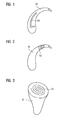
- FIG. 1 An example of an invention formed on the hearing aid housing RF antenna is shown in FIG.
- the L-shaped HF Antenna HA is a metal layer on the BTE hearing aid housing HG angry.
- the RF antenna HA as a preformed film formation on the HG hearing aid housing applied or by subsequent Structuring a metallization of the hearing aid housing HG educated.
- the RF antenna HA as already mentioned, as a conductive plastic layer during injection molding the hearing aid housing HG formed in the desired shape become.
- FIG. 1 Another embodiment of a hearing aid according to the invention is shown in FIG.
- the coil shown there SU has a helical character and turns around it Housing, which is also in this FIG 2 as a BTE hearing aid housing HG is shown.
- the coil SU is in a housing section formed and the axis of the coil SU corresponds to the Longitudinal axis of this housing section.
- FIG 3 A third embodiment of the present invention is disclosed in FIG 3 outlines.
- a spiral-shaped antenna SI is on the outwardly facing side of an IDO hearing aid housing IG appropriate.
- This hearing aid housing IG could but also, for example with a coil-shaped as shown in FIG Antenna equipped in the conical housing area be.
- a BTE case with a be provided spiral antenna is disclosed in FIG 3 outlines.
- the by the conductor layer generated device to the respective application be optimally adapted. This can be the profit, the directivity and the impedance in corresponding Influence way.
- several layers of Conductor layer superimposed within the shell layer be used to use the housing material as a dielectric.
Landscapes
- Engineering & Computer Science (AREA)
- Computer Networks & Wireless Communication (AREA)
- Health & Medical Sciences (AREA)
- General Health & Medical Sciences (AREA)
- Neurosurgery (AREA)
- Otolaryngology (AREA)
- Physics & Mathematics (AREA)
- Acoustics & Sound (AREA)
- Signal Processing (AREA)
- Support Of Aerials (AREA)
- Details Of Aerials (AREA)
- Finger-Pressure Massage (AREA)
- Adornments (AREA)
- Transmitters (AREA)
- Structure Of Receivers (AREA)
- Variable-Direction Aerials And Aerial Arrays (AREA)
Abstract
Description
Die vorliegende Erfindung betrifft ein Hörgerät mit einem Gehäuse und einer HF-Antenne und/oder elektrischen Spule zur elektromagnetischen Energie- und/oder Datenübertragung.The present invention relates to a hearing aid with a housing and an RF antenna and / or electrical coil for electromagnetic energy and / or data transmission.
Grundsätzlich ist man bestrebt, Hörgeräte möglichst klein zu gestalten. Andererseits sollen zur Erhöhung der Funktionalität des Hörgeräts möglichst viele Elektronikkomponenten in dem Hörgerät untergebracht werden. Daher ist die Miniaturisierung bzw. Ausstattung von Hörgeräten unter anderem durch die Abmessungen von beispielsweise Telefonspulen, Akku-Ladespulen oder HF-Antennen zur drahtlosen Kommunikation limitiert.Basically, one strives to hearing aids as small as possible shape. On the other hand, to increase the functionality the hearing aid as many electronic components in the hearing aid are housed. Therefore, the miniaturization or equipment of hearing aids, inter alia by the dimensions of, for example, telecoils, battery charging coils or HF antennas for wireless communication limited.
Gleichzeitig wird versucht, die notwendigen Komponenten, wie z. B. Spulen, mit den gewünschten Eigenschaften soweit wie möglich zu verkleinern, so dass sie im Gerät nur wenig Einbauraum benötigen. So werden beispielsweise HF-Antennen verwendet, die in die Leiterplatten der Hörgeräteelektronik integriert sind. Derartige auf Leiterplatten gedruckte Antennen sind beispielsweise aus dem WHITE PAPER "λ/4 printed monopole antenna for 2.45GHz" von Nordic VLSI ASA, Februar 2003 bekannt.At the same time trying to find the necessary components, such as z. As coils, with the desired properties as far as possible to shrink, so that they have little installation space in the device need. For example, HF antennas are used integrated into the circuit boards of the hearing aid electronics are. Such printed on printed circuit boards antennas are for example from the WHITE PAPER "λ / 4 printed monopole antenna for 2.45GHz "by Nordic VLSI ASA, February 2003.
Des Weiteren sind aus den Druckschriften US 4,495,917 und US 6,272,382 implantierbare Hörgeräte mit Induktionsspulen bekannt. In beiden Fällen sind die Spulen in eine Vergussmasse am Außenumfang des jeweiligen Hörgeräts eingebettet. Dabei ist jeweils ein klassischer Spulenaufbau mit mehreren Windungen in zahlreichen Ebenen gegeben.Furthermore, from the documents US 4,495,917 and US 6,272,382 implantable hearing aids with induction coils known. In both cases, the coils are in a potting compound embedded on the outer circumference of the respective hearing aid. there is in each case a classic coil construction with several turns given in numerous levels.
Aus der Druckschrift DE 101 15 896 A1 ist ein Hörgerätesystem mit einem programmierbaren Hörgerät und einer Sende- und Empfangseinheit bekannt. Im Gehäuse des Hörgeräts ist für die Sende- und Empfangseinheit eine Antenne angeordnet.From the document DE 101 15 896 A1 is a hearing aid system with a programmable hearing aid and a transmitting and receiving unit known. In the housing of the hearing aid is for the Transmitting and receiving unit arranged an antenna.
Des Weiteren ist aus der Druckschrift DE 34 43 907 eine Hörerkapsel für Hörbehinderte mit einer Induktionsspule bebekannt. Die Induktionsspule ist mit einem Flansch an der Hörerkapsel befestigt.Furthermore, from the document DE 34 43 907 a listener capsule for the hearing impaired with an induction coil known. The induction coil is fitted with a flange on the earpiece capsule attached.
Nachteilig an den bekannten Spulen ist, dass sie nach wie vor verhältnismäßig viel Einbauraum benötigen.A disadvantage of the known coils is that they are still need a relatively large amount of installation space.
Die Aufgabe der vorliegenden Erfindung besteht somit darin, den für Spulen von Hörgeräten notwendigen Einbauraum weiter zu verkleinern.The object of the present invention is therefore to the necessary installation space for coils of hearing aids on to downsize.
Erfindungsgemäß wird diese Aufgabe gelöst durch ein Hörgerät mit einem Gehäuse und einer HF-Antenne und/oder elektrischen Spule zur elektromagnetischen Energie- und/oder Datenübertragung, wobei die HF-Antenne und/oder die elektrische Spule im Material des Gehäuses oder an dem Gehäuse als elektrisch leitende Schicht ausgebildet ist.According to the invention this object is achieved by a hearing aid with a housing and an RF antenna and / or electrical Coil for electromagnetic energy and / or data transmission, wherein the RF antenna and / or the electrical coil in Material of the housing or on the housing as electrically conductive Layer is formed.
Durch das erfindungsgemäße Anbringen einer aus einer leitenden Schicht gebildeten Spule an das Hörgerätegehäuse bzw. deren Integration in ein Gehäuse kann das Gesamtvolumen eines Hörgeräts weiter verkleinert werden. Für manche Hörgeräte wird hierdurch erst die Möglichkeit eröffnet, ein HF-System zu integrieren.By attaching one of a conductive Layer formed coil to the hearing aid housing or their Integration into a housing can reduce the total volume of a Hearing be further reduced. For some hearing aids This opens up the possibility of an HF system to integrate.
Vorzugsweise ist die elektrisch leitende Schicht durch eine Metallisierung, die nachträglich strukturiert wurde, gebildet. Dadurch kann der Metallisierungsprozess des Hörgerätsgehäuses sehr einfach gestaltet werden.Preferably, the electrically conductive layer is through a Metallization, which was subsequently structured, formed. As a result, the metallization process of the hearing aid housing be very simple.
Es kann aber auch vorteilhaft sein, die elektrisch leitende Schicht als strukturierte Metallschicht an der Innen- oder Außenseite des Gehäuses aufzubringen. Dadurch kann ein unter Umständen aufwändiger Strukturierungsprozess vermieden werden.But it may also be advantageous, the electrically conductive Layer as a structured metal layer on the interior or Apply outside of the housing. This can be an under Circumstances consuming structuring process can be avoided.
Eine weitere Variante für die Herstellung einer Antenne oder Spule in Form einer elektrisch leitenden Schicht besteht darin, die elektrisch leitende Schicht in das Gehäuse einzugießen. Damit ist die Spule bzw. Antenne sicher gegen mechanische Einflüsse von außen geschützt.Another variant for making an antenna or Coil in the form of an electrically conductive layer is pour the electrically conductive layer into the housing. Thus, the coil or antenna is safe against mechanical Influences protected from the outside.
Die elektrisch leitende Schicht kann des Weiteren aus einem leitenden Kunststoffmaterial bestehen. Dadurch können bei der Herstellung der Spule bzw. Antenne die üblichen Kunststoffherstellungsprozesse Verwendung finden.The electrically conductive layer may further consist of a consist of conductive plastic material. This can help with the Production of the coil or antenna the usual plastic manufacturing processes Find use.
Die Antenne oder Spule kann ferner dadurch gebildet sein, dass in oder an dem Gehäuse mehrere Lagen der elektrisch leitenden Schicht übereinander angeordnet sind. Auf diese Weise lässt sich den räumlichen Gegebenheiten noch weiter Rechnung tragen, insbesondere wenn hohe Induktivitäten gefordert sind.The antenna or coil may further be formed by that in or on the housing a plurality of layers of the electrically conductive Layer are arranged one above the other. In this way allows the spatial conditions even further especially when high inductance is required.
Die Spule kann außerdem als ein das Gehäuse um dessen Längsachse umlaufender Leiter ausgebildet sein. Bei HdO-Hörgeräten hat dies beispielsweise den Vorteil, dass eine derartige, parallel zur Ohrmuschel ausgerichtete Spule gut als Telefonspule verwendet werden kann. Eine derartige, das Gehäuse umlaufende Spule kann auch dann verwendet werden, wenn das Gehäuse längsgeteilt ist. In diesem Fall wird die wendelförmige Spule durch das Zusammensetzen der Gehäusehälften gebildet. Auch jede andere Leiterstruktur kann sich über beide Gehäusehälften erstrecken.The coil may also be considered as the housing about its longitudinal axis be formed circumferential conductor. For BTE hearing aids For example, this has the advantage that such, in parallel to the auricle aligned coil well as a telecoil can be used. Such, the housing encircling Coil can also be used when the case is split longitudinally. In this case, the helical coil formed by the assembly of the housing halves. Also any other conductor structure can be over both housing halves extend.
Die vorliegende Erfindung wird nun anhand der beigefügten Zeichnungen näher erläutert, in denen zeigen:
- FIG 1
- ein HdO-Hörgerät mit einer Antenne gemäß einer ersten Ausführungsform;
- FIG 2
- ein HdO-Hörgerät mit einer Antenne gemäß einer zweiten Ausführungsform; und
- FIG 3
- ein IdO-Hörgerät mit einer Antenne gemäß einer dritten Ausführungsform der vorliegenden Erfindung.
- FIG. 1
- a BTE hearing aid with an antenna according to a first embodiment;
- FIG. 2
- a BTE hearing aid with an antenna according to a second embodiment; and
- FIG. 3
- an ITE hearing aid with an antenna according to a third embodiment of the present invention.
Die nachfolgend näher geschilderten Ausführungsbeispiele stellen bevorzugte Ausführungsformen der vorliegenden Erfindung dar.The embodiments described in more detail below represent preferred embodiments of the present invention represents.
Entsprechend der vorliegenden Erfindung wird ein in beliebiger Form strukturierter Leiter auf dem Hörgerätegehäuse aufgebracht. Vorzugsweise erfolgt dies an der Innenseite des Hörgerätegehäuses, um Beschädigungen der Leiterstruktur durch äußere Einflüsse zu vermeiden. Die Leiterstruktur kann aber auch auf der Außenseite des Hörgerätegehäuses angebracht werden, wobei es sich dann empfiehlt, eine Schutzschicht darüber aufzutragen.According to the present invention, a in any Form structured conductor applied to the hearing aid housing. This is preferably done on the inside of the Hearing aid housing to damage the conductor structure by to avoid external influences. But the ladder structure can also be mounted on the outside of the hearing aid housing, it is then recommended to have a protective layer over it apply.
Ein Beispiel einer erfindungsgemäßen am Hörgerätegehäuse gebildeten HF-Antenne ist in FIG 1 dargestellt. Die L-förmige HF-Antenne HA ist als Metallschicht auf dem HdO-Hörgerätegehäuse HG aufgebracht. Je nach bevorzugter Herstellungsart ist die HF-Antenne HA als vorgeformtes Foliengebilde auf das Hörgerätegehäuse HG aufgebracht oder durch nachträgliches Strukturieren einer Metallisierung des Hörgerätegehäuses HG gebildet. Alternativ kann die HF-Antenne HA, wie bereits erwähnt, als leitende Kunststoffschicht während des Spritzgießens des Hörgerätegehäuses HG in der gewünschten Form gebildet werden.An example of an invention formed on the hearing aid housing RF antenna is shown in FIG. The L-shaped HF Antenna HA is a metal layer on the BTE hearing aid housing HG angry. Depending on the preferred production method is the RF antenna HA as a preformed film formation on the HG hearing aid housing applied or by subsequent Structuring a metallization of the hearing aid housing HG educated. Alternatively, the RF antenna HA, as already mentioned, as a conductive plastic layer during injection molding the hearing aid housing HG formed in the desired shape become.
Ein weiteres Ausführungsbeispiel eines erfindungsgemäßen Hörgeräts ist in FIG 2 wiedergegeben. Die dort dargestellte Spule SU besitzt wendelförmigen Charakter und wendet sich um das Gehäuse, das auch in dieser FIG 2 als HdO-Hörgerätegehäuse HG dargestellt ist. Konkret ist die Spule SU in einem Gehäuseabschnitt ausgebildet und die Achse der Spule SU entspricht der Längsachse dieses Gehäuseabschnitts. Dabei kann die "Achse" bzw. "Längsachse" wie im vorliegenden Fall auch gekrümmt sein.Another embodiment of a hearing aid according to the invention is shown in FIG. The coil shown there SU has a helical character and turns around it Housing, which is also in this FIG 2 as a BTE hearing aid housing HG is shown. Concretely, the coil SU is in a housing section formed and the axis of the coil SU corresponds to the Longitudinal axis of this housing section. Here, the "axis" or "longitudinal axis" as in the present case also curved be.
Eine dritte Ausführungsform der vorliegenden Erfindung ist in FIG 3 skizziert. Dabei ist eine spiralförmige Antenne SI an der nach außen weisenden Seite eines IdO-Hörgerätegehäuses IG angebracht. Dieses Hörgerätegehäuse IG könnte aber auch beispielsweise mit einer wie in FIG 2 dargestellten spulenförmigen Antenne in dem konischen Gehäusebereich ausgestattet sein. Umgekehrt kann natürlich auch ein HdO-Gehäuse mit einer spiralförmigen Antenne versehen sein.A third embodiment of the present invention is disclosed in FIG 3 outlines. In this case, a spiral-shaped antenna SI is on the outwardly facing side of an IDO hearing aid housing IG appropriate. This hearing aid housing IG could but also, for example with a coil-shaped as shown in FIG Antenna equipped in the conical housing area be. Conversely, of course, a BTE case with a be provided spiral antenna.
Durch eine geeignete Wahl der Leitergeometrie kann das durch die Leiterschicht erzeugte Bauelement an die jeweilige Anwendung optimal angepasst werden. So lässt sich dadurch der Gewinn, die Richtwirkung und die Impedanz in entsprechender Weise beeinflussen. Daneben können auch mehrere Lagen der Leiterschicht innerhalb der Schalenschicht übereinander gelegt werden, um das Gehäusematerial als Dielektrikum zu nutzen.By a suitable choice of the conductor geometry, the by the conductor layer generated device to the respective application be optimally adapted. This can be the profit, the directivity and the impedance in corresponding Influence way. In addition, several layers of Conductor layer superimposed within the shell layer be used to use the housing material as a dielectric.
Claims (8)
Applications Claiming Priority (2)
| Application Number | Priority Date | Filing Date | Title |
|---|---|---|---|
| DE102004017832 | 2004-04-13 | ||
| DE102004017832A DE102004017832B3 (en) | 2004-04-13 | 2004-04-13 | hearing Aid |
Publications (3)
| Publication Number | Publication Date |
|---|---|
| EP1587343A2 true EP1587343A2 (en) | 2005-10-19 |
| EP1587343A3 EP1587343A3 (en) | 2006-01-18 |
| EP1587343B1 EP1587343B1 (en) | 2008-05-14 |
Family
ID=34939030
Family Applications (1)
| Application Number | Title | Priority Date | Filing Date |
|---|---|---|---|
| EP05102267A Expired - Lifetime EP1587343B1 (en) | 2004-04-13 | 2005-03-22 | Hearing-aid |
Country Status (8)
| Country | Link |
|---|---|
| US (1) | US20050244024A1 (en) |
| EP (1) | EP1587343B1 (en) |
| JP (1) | JP2005304038A (en) |
| CN (1) | CN1684548A (en) |
| AT (1) | ATE395802T1 (en) |
| AU (1) | AU2005201376B2 (en) |
| DE (2) | DE102004017832B3 (en) |
| DK (1) | DK1587343T3 (en) |
Cited By (12)
| Publication number | Priority date | Publication date | Assignee | Title |
|---|---|---|---|---|
| WO2008012355A1 (en) * | 2006-07-28 | 2008-01-31 | Siemens Audiologische Technik Gmbh | Antenna arrangement for hearing device applications |
| EP1915030A1 (en) * | 2006-10-16 | 2008-04-23 | Siemens Audiologische Technik GmbH | Hearing device with conducting metal clip |
| EP1959712A3 (en) * | 2007-02-16 | 2009-05-06 | Siemens Audiologische Technik GmbH | Hearing aid with hearing compensation coil |
| WO2009112898A2 (en) | 2008-03-13 | 2009-09-17 | Sony Ericsson Mobile Communications Ab | Antenna for use in earphone and earphone with integrated antenna |
| US8098858B2 (en) | 2006-10-16 | 2012-01-17 | Siemens Audiologische Technik Gmbh | Hearing device with current-conducting metal arm |
| EP2725655A1 (en) * | 2010-10-12 | 2014-04-30 | GN Resound A/S | An antenna system for a hearing aid |
| WO2014090419A1 (en) * | 2012-12-12 | 2014-06-19 | Siemens Medical Instruments Pte. Ltd. | Modular antenna for hearing devices |
| EP2835863A1 (en) | 2013-08-09 | 2015-02-11 | Oticon A/s | RF antenna and hearing device with RF antenna |
| US9408552B2 (en) | 2009-07-02 | 2016-08-09 | Widex A/S | Ear plug with surface electrodes |
| EP3101918A3 (en) * | 2015-05-13 | 2017-04-05 | Sivantos Pte. Ltd. | Hearing aid |
| US9980062B2 (en) | 2012-12-12 | 2018-05-22 | Sivantos Pte. Ltd. | Hearing aid and method for producing a hearing aid |
| EP3352296A1 (en) * | 2010-10-12 | 2018-07-25 | GN Hearing A/S | A hearing aid with an antenna |
Families Citing this family (64)
| Publication number | Priority date | Publication date | Assignee | Title |
|---|---|---|---|---|
| US7593538B2 (en) | 2005-03-28 | 2009-09-22 | Starkey Laboratories, Inc. | Antennas for hearing aids |
| US8041066B2 (en) | 2007-01-03 | 2011-10-18 | Starkey Laboratories, Inc. | Wireless system for hearing communication devices providing wireless stereo reception modes |
| US9774961B2 (en) | 2005-06-05 | 2017-09-26 | Starkey Laboratories, Inc. | Hearing assistance device ear-to-ear communication using an intermediate device |
| DE102005046169A1 (en) * | 2005-09-27 | 2007-04-05 | Siemens Audiologische Technik Gmbh | Hearing aid with an antenna |
| EP2257079B1 (en) | 2006-03-30 | 2012-01-04 | Phonak Ag | Wireless audio signal receiver device for a hearing instrument |
| US7548211B2 (en) | 2006-03-30 | 2009-06-16 | Phonak Ag | Wireless audio signal receiver device for a hearing instrument |
| US8208642B2 (en) | 2006-07-10 | 2012-06-26 | Starkey Laboratories, Inc. | Method and apparatus for a binaural hearing assistance system using monaural audio signals |
| US20080049945A1 (en) * | 2006-08-25 | 2008-02-28 | Phonak Ag | System for binaural hearing assistance |
| DE102006049470B4 (en) * | 2006-10-16 | 2011-06-22 | Siemens Audiologische Technik GmbH, 91058 | Hearing aid with a mounting device for a component of a hearing device and corresponding method |
| DE102007001537A1 (en) * | 2007-01-10 | 2008-07-17 | Siemens Audiologische Technik Gmbh | Influenzladevorrichtung and corresponding method |
| US8369959B2 (en) | 2007-05-31 | 2013-02-05 | Cochlear Limited | Implantable medical device with integrated antenna system |
| ES2443918T5 (en) * | 2007-12-27 | 2017-06-06 | Oticon A/S | Hearing device and procedure for receiving and / or sending wireless data |
| JP5252741B2 (en) | 2008-02-04 | 2013-07-31 | パナソニック株式会社 | Hearing aid |
| US8867765B2 (en) | 2008-02-06 | 2014-10-21 | Starkey Laboratories, Inc. | Antenna used in conjunction with the conductors for an audio transducer |
| US8565457B2 (en) | 2008-12-19 | 2013-10-22 | Starkey Laboratories, Inc. | Antennas for standard fit hearing assistance devices |
| US8494197B2 (en) | 2008-12-19 | 2013-07-23 | Starkey Laboratories, Inc. | Antennas for custom fit hearing assistance devices |
| US10142747B2 (en) | 2008-12-19 | 2018-11-27 | Starkey Laboratories, Inc. | Three dimensional substrate for hearing assistance devices |
| US8737658B2 (en) * | 2008-12-19 | 2014-05-27 | Starkey Laboratories, Inc. | Three dimensional substrate for hearing assistance devices |
| US8699733B2 (en) | 2008-12-19 | 2014-04-15 | Starkey Laboratories, Inc. | Parallel antennas for standard fit hearing assistance devices |
| EP2229009B1 (en) * | 2009-03-09 | 2013-10-30 | Oticon A/S | Hearing aid |
| US9420385B2 (en) | 2009-12-21 | 2016-08-16 | Starkey Laboratories, Inc. | Low power intermittent messaging for hearing assistance devices |
| US9432780B2 (en) | 2010-07-03 | 2016-08-30 | Starkey Laboratories, Inc. | Multi-mode radio for hearing assistance devices |
| CN103329350B (en) | 2010-10-12 | 2016-10-19 | Gn瑞声达A/S | Antenna device |
| JP5660870B2 (en) * | 2010-11-29 | 2015-01-28 | リオン株式会社 | Hearing aid transmitter coil |
| US8878735B2 (en) * | 2012-06-25 | 2014-11-04 | Gn Resound A/S | Antenna system for a wearable computing device |
| US20130343586A1 (en) * | 2012-06-25 | 2013-12-26 | Gn Resound A/S | Hearing aid having a slot antenna |
| DK201270410A (en) | 2012-07-06 | 2014-01-07 | Gn Resound As | BTE hearing aid with an antenna partition plane |
| DK201270411A (en) | 2012-07-06 | 2014-01-07 | Gn Resound As | BTE hearing aid having two driven antennas |
| US9554219B2 (en) | 2012-07-06 | 2017-01-24 | Gn Resound A/S | BTE hearing aid having a balanced antenna |
| US20140023216A1 (en) * | 2012-07-17 | 2014-01-23 | Starkey Laboratories, Inc. | Hearing assistance device with wireless communication for on- and off- body accessories |
| US9374650B2 (en) | 2012-07-17 | 2016-06-21 | Starkey Laboratories, Inc. | System and method for embedding conductive traces into hearing assistance device housings |
| US9237404B2 (en) | 2012-12-28 | 2016-01-12 | Gn Resound A/S | Dipole antenna for a hearing aid |
| US9414170B2 (en) * | 2012-12-28 | 2016-08-09 | Gn Resound A/S | Hearing aid having an adaptive antenna matching mechanism and a method for adaptively matching a hearing aid antenna |
| JP6513895B2 (en) * | 2013-02-20 | 2019-05-15 | 日東電工株式会社 | Mobile device and its charging device, mobile device charging system |
| DE102013210689B3 (en) | 2013-06-07 | 2014-10-02 | Siemens Medical Instruments Pte. Ltd. | Antenna device for hearing instruments |
| US9191757B2 (en) * | 2013-07-11 | 2015-11-17 | Starkey Laboratories, Inc. | Hearing aid with inductively coupled electromagnetic resonator antenna |
| US10985447B2 (en) | 2013-08-02 | 2021-04-20 | Gn Hearing A/S | Antenna device |
| KR102092857B1 (en) * | 2013-10-25 | 2020-03-25 | 삼성전자주식회사 | Leaky-wave antenna for hearing device |
| US9686621B2 (en) | 2013-11-11 | 2017-06-20 | Gn Hearing A/S | Hearing aid with an antenna |
| US9237405B2 (en) | 2013-11-11 | 2016-01-12 | Gn Resound A/S | Hearing aid with an antenna |
| US9408003B2 (en) | 2013-11-11 | 2016-08-02 | Gn Resound A/S | Hearing aid with an antenna |
| US9883295B2 (en) | 2013-11-11 | 2018-01-30 | Gn Hearing A/S | Hearing aid with an antenna |
| US10595138B2 (en) | 2014-08-15 | 2020-03-17 | Gn Hearing A/S | Hearing aid with an antenna |
| EP2992776B1 (en) * | 2014-09-04 | 2019-11-06 | WITS Co., Ltd. | Case and apparatus including the same |
| DK3038382T3 (en) * | 2014-12-22 | 2020-04-06 | Oticon As | ANTENNA DEVICE FOR A HEARING DEVICE |
| DE102015208845B3 (en) * | 2015-05-13 | 2016-08-11 | Sivantos Pte. Ltd. | hearing Aid |
| US10321248B2 (en) * | 2015-06-03 | 2019-06-11 | Gn Hearing A/S | Hearing device shell with guide structure |
| US10257624B2 (en) * | 2015-08-17 | 2019-04-09 | Starkey Laboratories, Inc. | Hearing aid wireless antenna molded into the device shell |
| EP3174314B1 (en) * | 2015-11-25 | 2020-04-01 | GN Hearing A/S | Ite hearing aid with improved wireless communication |
| WO2017153020A1 (en) * | 2016-08-01 | 2017-09-14 | Sivantos Pte. Ltd. | Hearing aid comprising an rf antenna |
| US10051388B2 (en) * | 2016-09-21 | 2018-08-14 | Starkey Laboratories, Inc. | Radio frequency antenna for an in-the-ear hearing device |
| CN106454655A (en) * | 2016-09-30 | 2017-02-22 | 常州阿木奇声学科技有限公司 | Loudspeaker and voice coil thereof |
| WO2019076570A1 (en) | 2017-10-16 | 2019-04-25 | Widex A/S | Antenna for a hearing assistance device |
| DK3471198T3 (en) | 2017-10-16 | 2021-01-11 | Widex As | ANTENNA FOR A HEARING SUPPORT DEVICE |
| DK3471201T3 (en) | 2017-10-16 | 2021-03-15 | Widex As | ANTENNA FOR A HEARING SUPPORT DEVICE |
| EP3471199B1 (en) | 2017-10-16 | 2024-06-05 | Widex A/S | Antenna for a hearing assistance device |
| DK3471200T3 (en) | 2017-10-16 | 2020-04-27 | Widex As | ANTENNA FOR A HEARING SUPPORT DEVICE |
| US10567891B1 (en) * | 2018-12-07 | 2020-02-18 | Starkey Laboratories, Inc. | Ear-wearable device having tunnel with receiver coil |
| US10764667B2 (en) | 2018-12-07 | 2020-09-01 | Starkey Laboratories, Inc. | Ear-wearable device having tunnel with electrical contact pins |
| WO2021003366A1 (en) * | 2019-07-03 | 2021-01-07 | Starkey Laboratories, Inc. | Circular polarized spiral antenna for hearing assistance devices |
| DE102020209124A1 (en) | 2020-07-21 | 2022-01-27 | Sivantos Pte. Ltd. | ITE hearing aid |
| EP3972288B1 (en) | 2020-09-17 | 2024-11-06 | Sonova AG | Hearing device |
| CN115299078A (en) * | 2021-02-05 | 2022-11-04 | 西万拓私人有限公司 | Space-saving magnetic induction antenna for hearing instruments |
| DE102022202761A1 (en) | 2022-03-21 | 2023-09-21 | Sivantos Pte. Ltd. | hearing aid |
Family Cites Families (12)
| Publication number | Priority date | Publication date | Assignee | Title |
|---|---|---|---|---|
| US4495917A (en) * | 1982-03-26 | 1985-01-29 | The Regents Of The University Of California | Surgically implantable disconnect device |
| AT378653B (en) * | 1983-12-07 | 1985-09-10 | Akg Akustische Kino Geraete | DYNAMIC HEAD CAPSULE FOR THE DISABLED |
| AT391047B (en) * | 1987-06-26 | 1990-08-10 | Siemens Ag | HEARING DEVICE WITH A CIRCUIT BOARD AND A HEAD COIL |
| DE69233156T2 (en) * | 1991-01-17 | 2004-07-08 | Adelman, Roger A. | IMPROVED HEARING AID |
| US6252550B1 (en) * | 1998-06-17 | 2001-06-26 | Peter Joseph Vernon | Planar antenna device |
| US6272382B1 (en) * | 1998-07-31 | 2001-08-07 | Advanced Bionics Corporation | Fully implantable cochlear implant system |
| EP1302092A2 (en) * | 2000-05-24 | 2003-04-16 | Sonionmicrotronic Nederland B.V. | An assembly comprising an electrical element |
| DE10115896C2 (en) * | 2001-03-30 | 2003-12-24 | Siemens Audiologische Technik | Transmitter and / or receiver unit, which can be releasably connected to a hearing aid, and a programmable hearing aid |
| US6710744B2 (en) * | 2001-12-28 | 2004-03-23 | Zarlink Semiconductor (U.S.) Inc. | Integrated circuit fractal antenna in a hearing aid device |
| DE10236469B3 (en) * | 2002-08-08 | 2004-02-12 | Siemens Audiologische Technik Gmbh | Wirelessly programmable hearing aid |
| US20040196996A1 (en) * | 2003-04-02 | 2004-10-07 | Feitel Mark A. | Hearing aid and hearing aid accessory cosmetic and functional cover |
| US7256747B2 (en) * | 2004-01-30 | 2007-08-14 | Starkey Laboratories, Inc. | Method and apparatus for a wireless hearing aid antenna |
-
2004
- 2004-04-13 DE DE102004017832A patent/DE102004017832B3/en not_active Expired - Fee Related
-
2005
- 2005-03-22 EP EP05102267A patent/EP1587343B1/en not_active Expired - Lifetime
- 2005-03-22 DE DE502005004075T patent/DE502005004075D1/en not_active Expired - Fee Related
- 2005-03-22 DK DK05102267T patent/DK1587343T3/en active
- 2005-03-22 AT AT05102267T patent/ATE395802T1/en not_active IP Right Cessation
- 2005-03-31 AU AU2005201376A patent/AU2005201376B2/en not_active Ceased
- 2005-04-05 CN CNA2005100628882A patent/CN1684548A/en active Pending
- 2005-04-12 JP JP2005114457A patent/JP2005304038A/en active Pending
- 2005-04-13 US US11/104,769 patent/US20050244024A1/en not_active Abandoned
Cited By (32)
| Publication number | Priority date | Publication date | Assignee | Title |
|---|---|---|---|---|
| US8098206B2 (en) | 2006-07-28 | 2012-01-17 | Siemens Audiologische Technik Gmbh | Antenna arrangement for hearing device applications |
| WO2008012355A1 (en) * | 2006-07-28 | 2008-01-31 | Siemens Audiologische Technik Gmbh | Antenna arrangement for hearing device applications |
| CN101166376B (en) * | 2006-10-16 | 2011-07-06 | 西门子测听技术有限责任公司 | Hearing aid with conductive metal bow |
| EP1915030A1 (en) * | 2006-10-16 | 2008-04-23 | Siemens Audiologische Technik GmbH | Hearing device with conducting metal clip |
| US8098858B2 (en) | 2006-10-16 | 2012-01-17 | Siemens Audiologische Technik Gmbh | Hearing device with current-conducting metal arm |
| EP1959712A3 (en) * | 2007-02-16 | 2009-05-06 | Siemens Audiologische Technik GmbH | Hearing aid with hearing compensation coil |
| US7652628B2 (en) | 2008-03-13 | 2010-01-26 | Sony Ericsson Mobile Communications Ab | Antenna for use in earphone and earphone with integrated antenna |
| WO2009112898A3 (en) * | 2008-03-13 | 2010-04-15 | Sony Ericsson Mobile Communications Ab | Antenna for use in earphone and earphone with integrated antenna |
| WO2009112898A2 (en) | 2008-03-13 | 2009-09-17 | Sony Ericsson Mobile Communications Ab | Antenna for use in earphone and earphone with integrated antenna |
| US11161306B2 (en) | 2009-07-02 | 2021-11-02 | T&W Engineering A/S | Ear plug with surface electrodes |
| US9408552B2 (en) | 2009-07-02 | 2016-08-09 | Widex A/S | Ear plug with surface electrodes |
| EP2725655A1 (en) * | 2010-10-12 | 2014-04-30 | GN Resound A/S | An antenna system for a hearing aid |
| EP3352296A1 (en) * | 2010-10-12 | 2018-07-25 | GN Hearing A/S | A hearing aid with an antenna |
| WO2014090419A1 (en) * | 2012-12-12 | 2014-06-19 | Siemens Medical Instruments Pte. Ltd. | Modular antenna for hearing devices |
| US9571944B2 (en) | 2012-12-12 | 2017-02-14 | Sivantos Pte. Ltd. | Hearing aid and method for producing a hearing aid |
| US9980062B2 (en) | 2012-12-12 | 2018-05-22 | Sivantos Pte. Ltd. | Hearing aid and method for producing a hearing aid |
| US9961457B2 (en) | 2013-08-09 | 2018-05-01 | Oticon A/S | RF antenna and hearing device with RF antenna |
| EP2835863A1 (en) | 2013-08-09 | 2015-02-11 | Oticon A/s | RF antenna and hearing device with RF antenna |
| US12284489B2 (en) | 2013-08-09 | 2025-04-22 | Oticon A/S | RF antenna and hearing device with RF antenna |
| US10136230B2 (en) | 2013-08-09 | 2018-11-20 | Oticon A/S | RF antenna and hearing device with RF antenna |
| US12028686B2 (en) | 2013-08-09 | 2024-07-02 | Oticon A/S | RF antenna and hearing device with RF antenna |
| US10306382B2 (en) | 2013-08-09 | 2019-05-28 | Oticon A/S | RF antenna and hearing device with RF antenna |
| US10555097B2 (en) | 2013-08-09 | 2020-02-04 | Oticon A/S | RF antenna and hearing device with RF antenna |
| EP3657600A1 (en) | 2013-08-09 | 2020-05-27 | Oticon A/s | Hearing device with rf antenna |
| US10779095B2 (en) | 2013-08-09 | 2020-09-15 | Oticon A/S | RF antenna and hearing device with RF antenna |
| US10966037B2 (en) | 2013-08-09 | 2021-03-30 | Oticon A/S | RF antenna and hearing device with RF antenna |
| US9680209B2 (en) | 2013-08-09 | 2017-06-13 | Oticon A/S | RF antenna and hearing device with RF antenna |
| US11228850B2 (en) | 2013-08-09 | 2022-01-18 | Oticon A/S | RF antenna and hearing device with RF antenna |
| US11546706B2 (en) | 2013-08-09 | 2023-01-03 | Oticon A/S | RF antenna and hearing device with RF antenna |
| US11750986B2 (en) | 2013-08-09 | 2023-09-05 | Oticon A/S | RF antenna and hearing device with RF antenna |
| US10200799B2 (en) | 2015-05-13 | 2019-02-05 | Sivantos Pte. Ltd. | Hearing device with sealed microphone opening |
| EP3101918A3 (en) * | 2015-05-13 | 2017-04-05 | Sivantos Pte. Ltd. | Hearing aid |
Also Published As
| Publication number | Publication date |
|---|---|
| ATE395802T1 (en) | 2008-05-15 |
| AU2005201376A1 (en) | 2005-10-27 |
| CN1684548A (en) | 2005-10-19 |
| EP1587343A3 (en) | 2006-01-18 |
| JP2005304038A (en) | 2005-10-27 |
| EP1587343B1 (en) | 2008-05-14 |
| DE102004017832B3 (en) | 2005-10-20 |
| AU2005201376B2 (en) | 2007-07-05 |
| US20050244024A1 (en) | 2005-11-03 |
| DK1587343T3 (en) | 2008-09-08 |
| DE502005004075D1 (en) | 2008-06-26 |
Similar Documents
| Publication | Publication Date | Title |
|---|---|---|
| EP1587343B1 (en) | Hearing-aid | |
| EP1851823B1 (en) | Double helix antenna | |
| DE69906973T2 (en) | Antenna structure that forms a housing for electronic components of a portable device | |
| EP3413587B1 (en) | Hearing aid, in particular behind the ear hearing aid | |
| EP3484179B1 (en) | Hearing aid | |
| DE69515375T2 (en) | Antenna arrangement and electrical device containing the same | |
| DE19713929A1 (en) | Transmitting and receiving antenna system | |
| DE60121103T2 (en) | antenna | |
| EP3490272B1 (en) | Batch of listening devices and method for producing a batch of listening devices | |
| EP3567672B1 (en) | Hearing aid with integrated antenna and electronics frame | |
| EP4258694A1 (en) | Hearing aid, in particular an in-the-ear hearing aid | |
| EP2034770A2 (en) | Transfer device for a hearing aid with film conductor shielding and shielded coil | |
| DE102021201095A1 (en) | Space-saving antenna for a hearing instrument | |
| DE4436157C2 (en) | antenna | |
| EP3944637B1 (en) | Ite hearing aid | |
| EP3826327B1 (en) | Hearing aid | |
| WO2018024392A1 (en) | Hearing aid comprising an rf antenna | |
| DE102011076246B4 (en) | Multi-band arrangement for radio signals and method for producing an associated exciter structure | |
| EP4104458B1 (en) | Space efficient magnetic-inductive antenna for hearing aid | |
| EP3016201B1 (en) | Antenna device | |
| EP2911312B1 (en) | Antenna with screening device and manufacturing method | |
| DE102008033881A1 (en) | Rod antenna with partially different antenna conductor structures | |
| DE102017220187A1 (en) | hearing aid | |
| DE102021214085A1 (en) | Space-saving antenna for a hearing instrument | |
| DE102016117415B4 (en) | High-frequency filter with improved signal coupling or signal extraction |
Legal Events
| Date | Code | Title | Description |
|---|---|---|---|
| PUAI | Public reference made under article 153(3) epc to a published international application that has entered the european phase |
Free format text: ORIGINAL CODE: 0009012 |
|
| AK | Designated contracting states |
Kind code of ref document: A2 Designated state(s): AT BE BG CH CY CZ DE DK EE ES FI FR GB GR HU IE IS IT LI LT LU MC NL PL PT RO SE SI SK TR |
|
| AX | Request for extension of the european patent |
Extension state: AL BA HR LV MK YU |
|
| PUAL | Search report despatched |
Free format text: ORIGINAL CODE: 0009013 |
|
| AK | Designated contracting states |
Kind code of ref document: A3 Designated state(s): AT BE BG CH CY CZ DE DK EE ES FI FR GB GR HU IE IS IT LI LT LU MC NL PL PT RO SE SI SK TR |
|
| AX | Request for extension of the european patent |
Extension state: AL BA HR LV MK YU |
|
| 17P | Request for examination filed |
Effective date: 20060206 |
|
| AKX | Designation fees paid |
Designated state(s): AT BE BG CH CY CZ DE DK EE ES FI FR GB GR HU IE IS IT LI LT LU MC NL PL PT RO SE SI SK TR |
|
| GRAP | Despatch of communication of intention to grant a patent |
Free format text: ORIGINAL CODE: EPIDOSNIGR1 |
|
| GRAS | Grant fee paid |
Free format text: ORIGINAL CODE: EPIDOSNIGR3 |
|
| GRAA | (expected) grant |
Free format text: ORIGINAL CODE: 0009210 |
|
| AK | Designated contracting states |
Kind code of ref document: B1 Designated state(s): AT BE BG CH CY CZ DE DK EE ES FI FR GB GR HU IE IS IT LI LT LU MC NL PL PT RO SE SI SK TR |
|
| REG | Reference to a national code |
Ref country code: GB Ref legal event code: FG4D Free format text: NOT ENGLISH |
|
| REG | Reference to a national code |
Ref country code: CH Ref legal event code: EP |
|
| REG | Reference to a national code |
Ref country code: IE Ref legal event code: FG4D Free format text: LANGUAGE OF EP DOCUMENT: GERMAN |
|
| REG | Reference to a national code |
Ref country code: CH Ref legal event code: NV Representative=s name: SIEMENS SCHWEIZ AG |
|
| REF | Corresponds to: |
Ref document number: 502005004075 Country of ref document: DE Date of ref document: 20080626 Kind code of ref document: P |
|
| PG25 | Lapsed in a contracting state [announced via postgrant information from national office to epo] |
Ref country code: SI Free format text: LAPSE BECAUSE OF FAILURE TO SUBMIT A TRANSLATION OF THE DESCRIPTION OR TO PAY THE FEE WITHIN THE PRESCRIBED TIME-LIMIT Effective date: 20080514 |
|
| PG25 | Lapsed in a contracting state [announced via postgrant information from national office to epo] |
Ref country code: FI Free format text: LAPSE BECAUSE OF FAILURE TO SUBMIT A TRANSLATION OF THE DESCRIPTION OR TO PAY THE FEE WITHIN THE PRESCRIBED TIME-LIMIT Effective date: 20080514 Ref country code: ES Free format text: LAPSE BECAUSE OF FAILURE TO SUBMIT A TRANSLATION OF THE DESCRIPTION OR TO PAY THE FEE WITHIN THE PRESCRIBED TIME-LIMIT Effective date: 20080825 |
|
| NLV1 | Nl: lapsed or annulled due to failure to fulfill the requirements of art. 29p and 29m of the patents act | ||
| PG25 | Lapsed in a contracting state [announced via postgrant information from national office to epo] |
Ref country code: NL Free format text: LAPSE BECAUSE OF FAILURE TO SUBMIT A TRANSLATION OF THE DESCRIPTION OR TO PAY THE FEE WITHIN THE PRESCRIBED TIME-LIMIT Effective date: 20080514 Ref country code: PL Free format text: LAPSE BECAUSE OF FAILURE TO SUBMIT A TRANSLATION OF THE DESCRIPTION OR TO PAY THE FEE WITHIN THE PRESCRIBED TIME-LIMIT Effective date: 20080514 |
|
| PG25 | Lapsed in a contracting state [announced via postgrant information from national office to epo] |
Ref country code: IS Free format text: LAPSE BECAUSE OF FAILURE TO SUBMIT A TRANSLATION OF THE DESCRIPTION OR TO PAY THE FEE WITHIN THE PRESCRIBED TIME-LIMIT Effective date: 20080914 |
|
| REG | Reference to a national code |
Ref country code: IE Ref legal event code: FD4D |
|
| PG25 | Lapsed in a contracting state [announced via postgrant information from national office to epo] |
Ref country code: CZ Free format text: LAPSE BECAUSE OF FAILURE TO SUBMIT A TRANSLATION OF THE DESCRIPTION OR TO PAY THE FEE WITHIN THE PRESCRIBED TIME-LIMIT Effective date: 20080514 Ref country code: IE Free format text: LAPSE BECAUSE OF FAILURE TO SUBMIT A TRANSLATION OF THE DESCRIPTION OR TO PAY THE FEE WITHIN THE PRESCRIBED TIME-LIMIT Effective date: 20080514 Ref country code: LT Free format text: LAPSE BECAUSE OF FAILURE TO SUBMIT A TRANSLATION OF THE DESCRIPTION OR TO PAY THE FEE WITHIN THE PRESCRIBED TIME-LIMIT Effective date: 20080514 Ref country code: SE Free format text: LAPSE BECAUSE OF FAILURE TO SUBMIT A TRANSLATION OF THE DESCRIPTION OR TO PAY THE FEE WITHIN THE PRESCRIBED TIME-LIMIT Effective date: 20080814 |
|
| PG25 | Lapsed in a contracting state [announced via postgrant information from national office to epo] |
Ref country code: PT Free format text: LAPSE BECAUSE OF FAILURE TO SUBMIT A TRANSLATION OF THE DESCRIPTION OR TO PAY THE FEE WITHIN THE PRESCRIBED TIME-LIMIT Effective date: 20081014 Ref country code: RO Free format text: LAPSE BECAUSE OF FAILURE TO SUBMIT A TRANSLATION OF THE DESCRIPTION OR TO PAY THE FEE WITHIN THE PRESCRIBED TIME-LIMIT Effective date: 20080514 Ref country code: SK Free format text: LAPSE BECAUSE OF FAILURE TO SUBMIT A TRANSLATION OF THE DESCRIPTION OR TO PAY THE FEE WITHIN THE PRESCRIBED TIME-LIMIT Effective date: 20080514 |
|
| PLBE | No opposition filed within time limit |
Free format text: ORIGINAL CODE: 0009261 |
|
| STAA | Information on the status of an ep patent application or granted ep patent |
Free format text: STATUS: NO OPPOSITION FILED WITHIN TIME LIMIT |
|
| REG | Reference to a national code |
Ref country code: CH Ref legal event code: PCAR Free format text: SIEMENS SCHWEIZ AG;INTELLECTUAL PROPERTY FREILAGERSTRASSE 40;8047 ZUERICH (CH) |
|
| 26N | No opposition filed |
Effective date: 20090217 |
|
| PG25 | Lapsed in a contracting state [announced via postgrant information from national office to epo] |
Ref country code: EE Free format text: LAPSE BECAUSE OF FAILURE TO SUBMIT A TRANSLATION OF THE DESCRIPTION OR TO PAY THE FEE WITHIN THE PRESCRIBED TIME-LIMIT Effective date: 20080514 Ref country code: BG Free format text: LAPSE BECAUSE OF FAILURE TO SUBMIT A TRANSLATION OF THE DESCRIPTION OR TO PAY THE FEE WITHIN THE PRESCRIBED TIME-LIMIT Effective date: 20080814 |
|
| BERE | Be: lapsed |
Owner name: SIEMENS AUDIOLOGISCHE TECHNIK G.M.B.H. Effective date: 20090331 |
|
| PG25 | Lapsed in a contracting state [announced via postgrant information from national office to epo] |
Ref country code: MC Free format text: LAPSE BECAUSE OF NON-PAYMENT OF DUE FEES Effective date: 20090331 |
|
| REG | Reference to a national code |
Ref country code: CH Ref legal event code: PL |
|
| REG | Reference to a national code |
Ref country code: DK Ref legal event code: EBP |
|
| GBPC | Gb: european patent ceased through non-payment of renewal fee |
Effective date: 20090322 |
|
| REG | Reference to a national code |
Ref country code: FR Ref legal event code: ST Effective date: 20091130 |
|
| PG25 | Lapsed in a contracting state [announced via postgrant information from national office to epo] |
Ref country code: CH Free format text: LAPSE BECAUSE OF NON-PAYMENT OF DUE FEES Effective date: 20090331 Ref country code: LI Free format text: LAPSE BECAUSE OF NON-PAYMENT OF DUE FEES Effective date: 20090331 Ref country code: DE Free format text: LAPSE BECAUSE OF NON-PAYMENT OF DUE FEES Effective date: 20091001 |
|
| PG25 | Lapsed in a contracting state [announced via postgrant information from national office to epo] |
Ref country code: BE Free format text: LAPSE BECAUSE OF NON-PAYMENT OF DUE FEES Effective date: 20090331 |
|
| PG25 | Lapsed in a contracting state [announced via postgrant information from national office to epo] |
Ref country code: DK Free format text: LAPSE BECAUSE OF NON-PAYMENT OF DUE FEES Effective date: 20090331 Ref country code: GB Free format text: LAPSE BECAUSE OF NON-PAYMENT OF DUE FEES Effective date: 20090322 Ref country code: FR Free format text: LAPSE BECAUSE OF NON-PAYMENT OF DUE FEES Effective date: 20091123 |
|
| PG25 | Lapsed in a contracting state [announced via postgrant information from national office to epo] |
Ref country code: AT Free format text: LAPSE BECAUSE OF NON-PAYMENT OF DUE FEES Effective date: 20090322 |
|
| PG25 | Lapsed in a contracting state [announced via postgrant information from national office to epo] |
Ref country code: GR Free format text: LAPSE BECAUSE OF FAILURE TO SUBMIT A TRANSLATION OF THE DESCRIPTION OR TO PAY THE FEE WITHIN THE PRESCRIBED TIME-LIMIT Effective date: 20080815 |
|
| PG25 | Lapsed in a contracting state [announced via postgrant information from national office to epo] |
Ref country code: IT Free format text: LAPSE BECAUSE OF NON-PAYMENT OF DUE FEES Effective date: 20090322 |
|
| PG25 | Lapsed in a contracting state [announced via postgrant information from national office to epo] |
Ref country code: LU Free format text: LAPSE BECAUSE OF NON-PAYMENT OF DUE FEES Effective date: 20090322 |
|
| PG25 | Lapsed in a contracting state [announced via postgrant information from national office to epo] |
Ref country code: HU Free format text: LAPSE BECAUSE OF FAILURE TO SUBMIT A TRANSLATION OF THE DESCRIPTION OR TO PAY THE FEE WITHIN THE PRESCRIBED TIME-LIMIT Effective date: 20081115 |
|
| PG25 | Lapsed in a contracting state [announced via postgrant information from national office to epo] |
Ref country code: TR Free format text: LAPSE BECAUSE OF FAILURE TO SUBMIT A TRANSLATION OF THE DESCRIPTION OR TO PAY THE FEE WITHIN THE PRESCRIBED TIME-LIMIT Effective date: 20080514 |
|
| PG25 | Lapsed in a contracting state [announced via postgrant information from national office to epo] |
Ref country code: CY Free format text: LAPSE BECAUSE OF FAILURE TO SUBMIT A TRANSLATION OF THE DESCRIPTION OR TO PAY THE FEE WITHIN THE PRESCRIBED TIME-LIMIT Effective date: 20080514 |