EP1586929B1 - Anamorphic converter - Google Patents
Anamorphic converter Download PDFInfo
- Publication number
- EP1586929B1 EP1586929B1 EP05252164A EP05252164A EP1586929B1 EP 1586929 B1 EP1586929 B1 EP 1586929B1 EP 05252164 A EP05252164 A EP 05252164A EP 05252164 A EP05252164 A EP 05252164A EP 1586929 B1 EP1586929 B1 EP 1586929B1
- Authority
- EP
- European Patent Office
- Prior art keywords
- lens
- image
- lens unit
- image forming
- positive
- Prior art date
- Legal status (The legal status is an assumption and is not a legal conclusion. Google has not performed a legal analysis and makes no representation as to the accuracy of the status listed.)
- Expired - Lifetime
Links
- 230000003287 optical effect Effects 0.000 claims description 92
- 238000003384 imaging method Methods 0.000 claims description 40
- 230000014509 gene expression Effects 0.000 claims description 29
- 238000006243 chemical reaction Methods 0.000 claims description 23
- 238000006073 displacement reaction Methods 0.000 claims description 3
- 230000002441 reversible effect Effects 0.000 claims description 3
- 230000004075 alteration Effects 0.000 description 94
- 238000010586 diagram Methods 0.000 description 82
- 238000003780 insertion Methods 0.000 description 7
- 230000037431 insertion Effects 0.000 description 7
- 201000009310 astigmatism Diseases 0.000 description 6
- 210000001747 pupil Anatomy 0.000 description 5
- 239000011521 glass Substances 0.000 description 4
- 230000002093 peripheral effect Effects 0.000 description 4
- 238000000926 separation method Methods 0.000 description 4
- 206010010071 Coma Diseases 0.000 description 3
- 230000008859 change Effects 0.000 description 2
- 239000000463 material Substances 0.000 description 2
- 230000000694 effects Effects 0.000 description 1
- 230000007246 mechanism Effects 0.000 description 1
- 230000009467 reduction Effects 0.000 description 1
- 102220047090 rs6152 Human genes 0.000 description 1
- 230000000007 visual effect Effects 0.000 description 1
Images


Classifications
-
- G—PHYSICS
- G02—OPTICS
- G02B—OPTICAL ELEMENTS, SYSTEMS OR APPARATUS
- G02B13/00—Optical objectives specially designed for the purposes specified below
- G02B13/08—Anamorphotic objectives
-
- G—PHYSICS
- G02—OPTICS
- G02B—OPTICAL ELEMENTS, SYSTEMS OR APPARATUS
- G02B13/00—Optical objectives specially designed for the purposes specified below
- G02B13/08—Anamorphotic objectives
- G02B13/12—Anamorphotic objectives with variable magnification
-
- G—PHYSICS
- G02—OPTICS
- G02B—OPTICAL ELEMENTS, SYSTEMS OR APPARATUS
- G02B15/00—Optical objectives with means for varying the magnification
- G02B15/02—Optical objectives with means for varying the magnification by changing, adding, or subtracting a part of the objective, e.g. convertible objective
Definitions
- the present invention relates to an anamorphic converter disposed at an image side of an image-forming optical system to convert an aspect ratio of an image.
- the present invention also relates to a lens system and a shooting system including the anamorphic converter and used in a television camera, a video camera, etc.
- Japanese Patent Laid-Open No. 2-13916 see lines 10 to 16 in the lower right column of page 2 and Fig. 1
- Japanese Patent Laid-Open No. 3-25407 see line 14 in the upper left column to line 6 in the upper right column of page 4 and Fig. 1
- Japanese Patent Laid-Open No. 5-188271 see paragraphs 0023 to 0025 and Fig. 1
- Japanese Patent Laid-Open No. 5-188272 see paragraphs 0022 to 0023 and Fig. 1
- Japanese Patent Laid-Open No. 6-82691 see paragraphs 0013 to 0015 and Figs. 1(A) and 1(B)
- Japanese Patent No. 2817074 see paragraph 0012 and Figs. 1 to 3 ).
- rear converters disposed at the image side of image-forming optical systems have also been suggested.
- An example of a rear converter is disclosed in Japanese Patent No. 3021985 (see paragraphs 0016 to 0017 and Figs. 1 to 3 ).
- anamorphic converters for digital cinemas it is preferable that desired aspect-ratio conversion be performed and shading of light from an object not to occur.
- an effective image plane of the image-forming optical system is efficiently used, reduction in the amount of peripheral light is small, and high optical performance is obtained at the entire zoom/focus area. It is also important that the above-described various aspect ratios are obtainable.
- front converters are advantageous in that they have simple structures and shading can be prevented irrespective of the conversion magnification by setting a suitable effective diameter.
- astigmatism varies during focusing.
- systems for correcting the astigmatism during focusing are suggested in Japanese Patent Publication No. 48-24048 and Japanese Patent Laid-Open Nos. 3-25407 , 5-188271 , and 5-188272 , a correcting unit included in the converter must be driven in association with the focusing performed by the image-forming optical system, and a complex mechanism is necessary.
- the present invention is directed to a lens system including an anamorphic converter which provides high optical performance and with which a magnification of an aspect ratio can be easily changed.
- an image forming lens system as specified in claims 1 to 13.
- a shooting system as specified in claim 14.
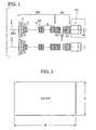
- Fig. 1 shows sectional views in the x and y directions of a lens system according to a first embodiment (numerical example 1) of the present invention at the wide-angle end.
- Fig. 2 is a schematic diagram showing an aspect ratio.
- Fig. 3 is a schematic diagram showing an image-forming section in an image plane of an image-forming optical system.
- Fig. 4 is a schematic diagram showing an effective image pickup area of an imaging device.
- Fig. 5 is a schematic diagram showing an image-forming section after a conversion performed by an anamorphic converter.
- Fig. 6 is a schematic diagram showing a display area of a projected image.
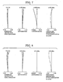
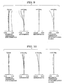
- Fig. 7 is a longitudinal aberration diagram in the x direction according to numerical example 1.
- Fig. 8 is another longitudinal aberration diagram in the x direction according to numerical example 1.
- Fig. 9 is another longitudinal aberration diagram in the x direction according to numerical example 1.
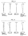
- Fig. 10 is a longitudinal aberration diagram in the y direction according to numerical example 1.
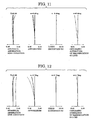
- Fig. 11 is another longitudinal aberration diagram in the y direction according to numerical example 1.
- Fig. 12 is another longitudinal aberration diagram in the y direction according to numerical example 1.
- Fig. 13 shows sectional views in the x and y directions of a lens system according to a second embodiment (numerical example 2) of the present invention at the wide-angle end.
- Fig. 14 is a longitudinal aberration diagram in the x direction according to numerical example 2.
- Fig. 15 is another longitudinal aberration diagram in the x direction according to numerical example 2.
- Fig. 16 is another longitudinal aberration diagram in the x direction according to numerical example 2.
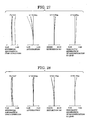
- Fig. 17 is a longitudinal aberration diagram in the y direction according to numerical example 2.
- Fig. 18 is another longitudinal aberration diagram in the y direction according to numerical example 2.
- Fig. 19 is another longitudinal aberration diagram in the y direction according to numerical example 2.
- Fig. 20 shows sectional views of a lens system according to a third embodiment (numerical example 3) of the present invention at the wide-angle end.
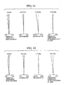
- Fig. 21 is a longitudinal aberration diagram according to numerical example 3.
- Fig. 22 is another longitudinal aberration diagram according to numerical example 3.
- Fig. 23 is another longitudinal aberration diagram according to numerical example 3.
- Fig. 24 shows sectional views in the x and y directions of a lens system according to a fourth embodiment (numerical example 4) of the present invention at the wide-angle end.
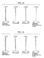
- Fig. 25 is a longitudinal aberration diagram in the x direction according to numerical example 4.
- Fig. 26 is a longitudinal aberration diagram in the y direction according to numerical example 4.
- Fig. 27 is another longitudinal aberration diagram in the x direction according to numerical example 4.
- Fig. 28 is another longitudinal aberration diagram in the y direction according to numerical example 4.
- Fig. 29 is another longitudinal aberration diagram in the x direction according to numerical example 4.
- Fig. 30 is another longitudinal aberration diagram in the y direction according to numerical example 4.
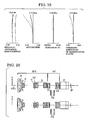
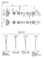
- Fig. 31 shows sectional views in the x and y directions of a lens system according to a fifth embodiment (numerical example 5) of the present invention at the wide-angle end.
- Fig. 32 a longitudinal aberration diagram in the x direction according to numerical example 5.
- Fig. 33 is another longitudinal aberration diagram in the x direction according to numerical example 5.
- Fig. 34 is another longitudinal aberration diagram in the x direction according to numerical example 5.
- Fig. 35 is a longitudinal aberration diagram in the y direction according to numerical example 5.
- Fig. 36 is another longitudinal aberration diagram in the y direction according to numerical example 5.
- Fig. 37 is another longitudinal aberration diagram in the y direction according to numerical example 5.
- Fig. 38 shows sectional views of a lens system according to a sixth embodiment (numerical example 6) of the present invention at the wide-angle end.
- Fig. 39 is a longitudinal aberration diagram according to numerical example 6.
- Fig. 40 is another longitudinal aberration diagram according to numerical example 6.
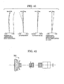
- Fig. 41 is another longitudinal aberration diagram according to numerical example 6.
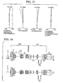
- Fig. 42 is a sectional view showing a lens system before the insertion of the anamorphic converter according to numerical examples 1 to 6.
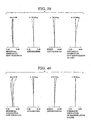
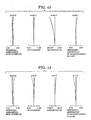
- Fig. 43 is a longitudinal aberration diagram obtained by the lens system before the insertion of the anamorphic converter according to numerical examples 1 to 6.
- Fig. 44 is another longitudinal aberration diagram obtained by the lens system before the insertion of the anamorphic converter according to numerical examples 1 to 6.
- Fig. 45 is another longitudinal aberration diagram obtained by the lens system before the insertion of the anamorphic converter according to numerical examples 1 to 6.
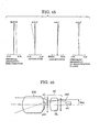
- Fig. 46 is a schematic diagram showing an anamorphic converter without primary imaging.
- Fig. 47 is a schematic diagram showing an anamorphic converter with primary imaging.
- Figs. 1 , 13 , 20 , 24 , 31 , and 38 show optical sectional views (y section and x section) in the vertical direction (y direction) and the horizontal direction (x direction) of lens systems according to first, second, third, fourth, fifth, and sixth embodiments, respectively, of the present invention at the wide-angle end.
- first, second, third, fourth, fifth, and sixth embodiments, respectively, of the present invention at the wide-angle end First, features common to all of the embodiments will be described.
- the lens system includes an image-forming optical system IFS included in commonly used picture-taking lenses (lenses used in video cameras, lenses for broadcasting, etc.) and an anamorphic converter AC disposed closer to an image side than the image-forming optical system IFS.
- image-forming optical system IFS included in commonly used picture-taking lenses (lenses used in video cameras, lenses for broadcasting, etc.)
- an anamorphic converter AC disposed closer to an image side than the image-forming optical system IFS.
- the second lens unit G2 is moveable (insertable/extractable) in a direction perpendicular to an optical axis, as shown by the arrow in the figures, between a first state in which it is disposed in a region between the first lens unit G1 and the third lens unit G3 (state shown in the figures) and a second state in which it is removed from this region.
- Equation (10) shows a condition for easily switching a magnification of an aspect ratio.
- Fig. 3 is a schematic diagram showing an image-forming section (image circle) IS of the image-forming optical system IFS
- Fig. 4 is a schematic diagram showing an effective image pickup area EPA of an imaging device.
- X1 and Y1 are the width and height, respectively, of an effective screen ES corresponding to (inscribed in) the image-forming section IS in the image plane (light-receiving surface of the imaging device) of the image-forming optical system IFS
- AR1 is an aspect ratio thereof.
- X2 and Y2 are the width and height, respectively, of the effective image pickup area EPA of the imaging device, and AR2 is an aspect ratio thereof.
- Fig. 5 is a schematic diagram showing an image-forming section IS' of the image-forming optical system IFS after the aspect-ratio conversion by the anamorphic converter AC and an effective screen ES' corresponding to the image-forming section IS'.
- Fig. 6 is a schematic diagram showing an image of a motion picture projected on a screen.
- an aspect-ratio conversion reverse to that performed when the image is shot must be performed so that the aspect ratio returns to the initial value.
- X4 and Y4 are the width and height, respectively, of a projected image PI
- X4 and Y4 are expressed as follows:
- X ⁇ 4 ⁇ x ⁇ ⁇ X ⁇ 2
- Y ⁇ 4 ⁇ y ⁇ ⁇ Y ⁇ 2
- magnifications ⁇ x' and ⁇ y' are expressed as follows using an arbitrary constant m:
- the aspect-ratio magnification can be easily switched without replacing the entire body of the anamorphic converter AC.
- the first and third lens units G1 and G3 function as a magnification-converting optical system.
- the first lens unit G1 may have a negative refractive power.
- both of the focal-length magnifications ⁇ x and ⁇ y must be positive.
- the anamorphic converter AC has a positive refractive power in both of the above-described x and y sections to suppress an effect of increasing the focal length.
- the first lens unit G1 may have a positive refractive power.
- Fig. 47 is a schematic diagram showing an anamorphic converter AC with primary imaging.
- both of the focal-length magnifications ⁇ x and ⁇ y must be negative.
- an entrance pupil in order to cover the peripheral light in the image-forming optical system IFS, an entrance pupil must substantially be the same as an exit pupil of the image-forming optical system IFS.
- a typical lens for broadcasting including a digital cinema lens is basically used together with a color-separation optical system, and therefore has a long exit pupil and is substantially telecentric on the image side. Accordingly, an optical system which is substantially telecentric on both the object side and the image side is required as a converter.
- a light beam (paraxial primary light ray ⁇ 1 and off-axis primary light ray ⁇ b1) from the image-forming optical system IFS is made substantially afocal by a positive lens PL. Accordingly, an output height hb3 of an off-axis primary light ray ⁇ b3 from the rearmost surface of the anamorphic converter AC is reduced, and the amount of peripheral light is prevented from being reduced.
- the exit pupil is increased and an influence of color shading caused by the color separation optical system does not easily occur.
- ⁇ 3 denotes a paraxial primary light ray emitted from the anamorphic converter AC.
- the anamorphic converter AC with primary imaging must be telecentric on both sides, the anamorphic converter AC includes at least two positive lens units and a refractive power of the overall anamorphic converter AC is very small and is close to zero.
- the state in which a system is approximately afocal means that the following expression is satisfied: - 0.1 ⁇ ⁇ ⁇ + 0.1 where ⁇ is an inclination angle standardized by the inclination angle of emission of the on-axis light ray from the rearmost surface.
- the anamorphic converter AC when ⁇ i, vi, and Ni are the refractive power, the Abbe number, and the refractive index, respectively, of each element included in the first to third lens units G1 to G3, a condition for chromatic aberration correction is expressed as follows: ⁇ ⁇ i / ⁇ i ⁇ 0
- the Petzval condition is expressed as follows: ⁇ ⁇ i / Ni ⁇ 0 Since normal optical materials satisfy vi>0 and Ni>0, in order to satisfy Expressions (11) and (12), the anamorphic converter AC with primary imaging includes at least one negative lens element.
- an anamorphic converter with primary imaging is obtained.
- the anamorphic converter AC satisfies the following condition: 0.9 ⁇ AR ⁇ 1 ⁇ ⁇ x / AR ⁇ 2 ⁇ ⁇ y ⁇ 1.1
- ⁇ x is the focal-length magnification in an arbitrary x section including an optical axis AXL of the overall anamorphic converter AC
- ⁇ y is the focal-length magnification in the y section which includes the optical axis AXL and which is perpendicular to the x section
- AR1 is the aspect ratio of the image-forming section in the image plane of the image-forming optical system IFS
- AR2 is the aspect ratio of the effective image pickup area of the imaging device.
- Equation (5) must be satisfied to perform an ideal aspect-ratio conversion, an error within ⁇ 10% causes only a small visual influence in practice. Accordingly, a satisfactory aspect-ratio conversion can be performed when Expression (13) is satisfied.
- the anamorphic converter AC satisfies the following expression: 1 ⁇ AR ⁇ 2 2 + 1 ⁇ ⁇ y 2 / AR ⁇ 1 2 + 1 ⁇ 2.6
- the anamorphic converter AC When the anamorphic converter AC is disposed at the image side of the image-forming optical system IFS, the image circle is limited by an effective diameter of the image-forming optical system. Therefore, the field angle cannot be increased even when the magnification is reduced to below 1, and shading occurs at the peripheral region.
- the second lens unit G2 may be rotatable about the optical axis.
- the direction of the aspect-ratio conversion can be selected arbitrarily.
- a gap between at least two lens elements included in the second lens unit G2 may be variable.
- the focal-length magnification can be varied continuously.
- the second lens unit G2 receives substantially collimated light.
- the second lens unit G2 may include at least one first anamorphic lens having a positive optical power in a section A which is perpendicular to the optical axis and at least one second anamorphic lens having a negative optical power in the section A.
- the second lens unit G2 can change at least an incidence height of an on-axis marginal light ray on the second lens unit G2 in the section A in order to change the focal-length magnifications ⁇ x and ⁇ y in the aspect-ratio conversion, and outputs the on-axis marginal light ray in a substantially parallel state so that an image is formed without generating on-axis astigmatism. This can be achieved by applying the above-described structure.
- the third lens unit G3 can include a plurality of positive lens elements and one or more negative lens elements and satisfies the following expression: ⁇ p ⁇ 3 - ⁇ n ⁇ 3 > 20 where vp3 is an average Abbe number of the positive lens elements and vn3 is an average Abbe number of the negative lens elements.
- the third lens unit G3 must adequately form an image of the approximately parallel light from the second lens unit G2 while adequately correcting aberrations.
- Aberrations including spherical aberration, coma aberration, and image-plane distortion can be corrected by combining a plurality of positive lens elements and one or more negative lens elements.
- Expression (20) shows a condition for correcting the chromatic aberration. When the value in this expression is reduced to below the lower limit, the refractive powers of both the positive and negative lens elements are increased and it becomes difficult to correct the above-described aberrations.
- the first lens unit G1 can include one or more positive lens elements and a plurality of negative lens elements and satisfies the following expression: ⁇ n ⁇ 1 - ⁇ p ⁇ 1 > 10 where ⁇ p1 is an average Abbe number of the positive lens elements and ⁇ n1 is an average Abbe number of the negative lens elements.
- the first lens unit G1 In the anamorphic converter without primary imaging, the first lens unit G1 must collimate the converging light from the image-forming optical system while correcting aberrations.
- Aberrations including spherical aberration, coma aberration, and image-plane distortion can be corrected by combining a plurality of negative lens elements and one or more positive lens elements.
- Expression (21) shows a condition for correcting the chromatic aberration. When the value in this expression is reduced to below the lower limit, the refractive powers of both the negative and positive lens elements increase and it becomes difficult to correct the above-described aberrations.
- the first lens unit G1 can include a plurality of positive lens elements and one or more negative lens elements and satisfies the following expression: ⁇ n ⁇ 1 - ⁇ p ⁇ 1 > 10 where vp1 is an average Abbe number of the positive lens elements and vn1 is an average Abbe number of the negative lens elements.
- the first lens unit G1 In the anamorphic converter with primary imaging, the first lens unit G1 must collimate the diverging light from the primary image of the image-forming optical system while correcting aberrations.
- Aberrations including spherical aberration, coma aberration, and image-plane distortion can be corrected by combining a plurality of positive lens elements and one or more negative lens elements.
- Expression (22) shows a condition for correcting the chromatic aberration. When the value in this expression is reduced to below the lower limit, the refractive powers of both the positive and negative lens elements increase and it becomes difficult to correct the above-described aberrations.
- the anamorphic lens used in each embodiment is, for example, a toric lens or a cylindrical lens in which optical powers in the x and y directions are different from each other.
- a diffractive optical element may also be adhered to a lens surface of the anamorphic lens used in each embodiment so that the anamorphic lens provides a function of diffraction.
- the image-forming optical system IFS may either be a variable power system (zoom lens) or a constant power system (fixed focal length lens).
- anamorphic converter AC In the anamorphic converter AC according to the first embodiment shown in Fig. 1 , primary imaging is not performed.
- the anamorphic converter AC shown in Fig. 1 corresponds to numerical example 1 described below.
- Fig. 42 shows an optical sectional view of a zoom lens which serves as the image-forming optical system IFS according to numerical examples 1 to 6.
- Figs. 43 to 45 show the longitudinal aberration diagrams of the zoom lens according to numerical examples 1 to 6.
- a front focusing lens F has a positive refractive power
- a variator V for varying the magnification and has a negative refractive power.
- the variator V moves along an optical axis toward the image plane for the variation of magnification from the wide-angle end to the telephoto end.
- a compensator C has a negative refractive power.
- the compensator C moves nonlinearly along the optical axis with a trajectory which is convex toward the object side in order to correct the displacement of the image plane during the variation of magnification.
- a variable power system is defined by the variator V and the compensator C.
- a diaphragm SP and a relay lens R which serves as a fourth lens unit and which has a positive refractive power are provided.
- the relay lens R is fixed during the variation of magnification.
- a glass block P such as a color separation prism and an optical filter is provided in a shooting apparatus VC, such as a video camera.
- a shooting apparatus VC such as a video camera.
- an imaging device IP such as a CCD sensor and a CMOS sensor is also provided in the shooting apparatus VC.
- the shooting apparatus VC is shown by the one-dot chain line in Fig. 1 , it is omitted in other embodiments.
- the anamorphic converter AC includes a first lens unit G1 which includes two negative lens elements and a single positive lens element and which has a negative refractive power, a second lens unit G2 which includes three cylindrical lens elements, and a third lens unit G3 which has an image-forming function, which includes three positive lens elements and a single negative lens element, and which has a positive refractive power.
- the value corresponding to Expression (20) is 28.6, and the value corresponding to Expression (21) is 17.0. Both of these values satisfy the corresponding conditions, and accordingly the aberrations are sufficiently corrected.
- Each of the three cylindrical lens elements included in the second lens unit G2 has a curvature only in the x direction, and reduces only the focal length in the x direction.
- the cylindrical lens used in the present embodiment is made of glass.
- fx denotes the focal length in the x direction
- fy denotes the focal length in the y direction
- Fx is the F-number in the x direction
- Fy is the F-number in the y direction.
- 2 ⁇ is the field angle.
- ri is the radius of curvature of the i th lens surface from the object side
- di is the distance between the i th and (i+1) th lens surfaces
- ni and vi shown as vi in each table
- ni and vi are the refractive index and the Abbe number, respectively, of the material of the i th lens element from the object side.
- the solid line shows the e-line
- the dashed line shows the F-line
- the one-dot chain line shows the C-line
- the two-dot chain line shows the g-line (this also applies to the aberration diagrams of other embodiments).
- ⁇ is shown as w.
- Curvatures in x and y directions are as follows: x y r40 646.757 0 r41 -132.193 0 r42 40.341 0 r43 65.604 0 r44 -68.100 0 Focal Length fx fy Variable Range 9.760 37.379 143.173 12.885 49.351 189.030 d7 0.39 33.92 49.55 d12 52.91 14.80 3.78 d15 1.55 6.13 1.53
- the anamorphic converter AC according to the second embodiment (numerical example 2) shown in Fig. 13 is similar to the anamorphic converter AC with primary imaging according to the first embodiment except the structure of the second lens unit G2 is changed.
- the structures of the zoom lens which functions as the image-forming optical system IFS and the first and third lens units G1 and G3 in the anamorphic converter AC are similar to those of the first embodiment.
- the anamorphic converter AC includes a first lens unit G1 which has a positive refractive power, a second lens unit G2' including three toric lens elements, and a third lens unit G3 which has an image-forming function and a positive refractive power.
- Each of the three cylindrical lens elements included in the second lens unit G2' has different curvatures in the x and y directions, and increases the focal length in the y direction with respect to that in the x direction.
- Curvatures in x and y directions are as follows: x y r40 567.567 584.961 r41 -158.236 -185.750 r42 47.220 55.837 r43 69.801 71.599 r44 -86.321 -120.593 Focal Length fx fy Variable Range 10.206 39.091 149.729 10.618 40.666 155.764 d7 0.39 33.92 49.55 d12 52.91 14.80 3.78 d15 1.55 6.13 1.53
- the anamorphic converter AC according to the third embodiment (numerical example 3) shown in Fig. 20 corresponds to the anamorphic converter AC according to the first embodiment in the state in which the second lens unit G2 is removed (second state).
- the structures of the zoom lens which function as the image-forming optical system IFS and the first and third lens units G1 and G3 in the anamorphic converter AC are similar to those of the first embodiment.
- the anamorphic converter AC includes a first lens unit G1 which has a positive refractive power and a third lens unit G3 which has an image-forming function and a positive refractive power.
- a function as a teleconverter magnification-converting optical system
- Fig. 24 shows the anamorphic converter AC with primary imaging according to the fourth embodiment (numerical example 4). Components included in the image-forming optical system IFS shown in Fig. 24 will be described below in the order from the object side.
- a front focusing lens F has a positive refractive power
- a variator V for varying the magnification and has a negative refractive power.
- the variator V moves along an optical axis toward the image plane for the variation of magnification from the wide-angle end to the telephoto end.
- a compensator C has a negative refractive power.
- the compensator C moves nonlinearly along the optical axis with a trajectory which is convex toward the object side in order to correct the displacement of the image plane during the variation of magnification.
- a variable power system is defined by the variator V and the compensator C.
- a diaphragm SP and a relay lens R which combine have a positive refractive power are provided.
- the relay lens R is fixed during the variation of magnification.
- a glass block P such as a color separation prism and an optical filter
- an imaging device IP is provided in a shooting apparatus.
- the anamorphic converter AC includes a first lens unit G1 which includes three positive lens elements and three negative lens elements and which has a positive refractive power, a second lens unit G2 which includes three cylindrical lens elements, and a third lens unit G3 which has an image-forming function, which includes three positive lens elements and two negative lens elements, and which has a positive refractive power.
- Each of the three cylindrical lens elements included in the second lens unit G2 has a curvature only in the x direction, and reduces only the focal length in the x direction.
- the cylindrical lens used in the present embodiment is made of glass.
- Curvatures in x and y directions are as follows: x y r45 -78.889 0 r46 -36.698 0 r47 209.589 0 r48 288.285 0 r49 -72.810 0 Focal Length fx fy Variable Range -9.759 -37.376 -143.160 -12.894 -49.383 -189.152 d7 0.39 33.92 49.55 d12 52.91 14.80 3.78 d15 1.55 6.13 1.53
- the anamorphic converter AC according to the fifth embodiment (numerical example 5) shown in Fig. 31 is similar to the anamorphic converter AC with primary imaging according to the fourth embodiment except the structure of the second lens unit G2 is changed.
- the structures of the zoom lens which functions as the image-forming optical system IFS and the first and third lens units G1 and G3 are similar to those of the fourth embodiment.
- the anamorphic converter AC includes a first lens unit G1 which has a positive refractive power, a second lens unit G2' including three toric lens elements, and a third lens unit G3 which has an image-forming function and a positive refractive power.
- Each of the three cylindrical lens elements included in the second lens unit G2' has different curvatures in the x and y directions, and increases the focal length in the y direction with respect to that in the x direction.
- Curvatures in x and y directions are as follows: x y r45 -81.973 -105.900 r46 -39.866 -58.265 r47 189.642 202.449 r48 218.599 183.157 r49 -75.076 -100.060 Focal Length fx fy Variable Range -10.207 -39.094 -149.741 -10.621 -40.679 -155.812 d7 0.39 33.92 49.55 d12 52.91 14.80 3.78 d15 1.55 6.13 1.53
- the anamorphic converter AC according to the sixth embodiment (numerical example 6) shown in Fig. 38 corresponds to the anamorphic converter AC according to the first embodiment in the state in which the second lens unit G2 is removed.
- the structures of the zoom lens which functions as the image-forming optical system IFS and the first and third lens units G1 and G3 in the anamorphic converter AC are similar to those of the fourth embodiment.
- the anamorphic converter AC includes a first lens unit G1 which has a positive refractive power and a third lens unit G3 which has an image-forming function and a positive refractive power.
- a function as a teleconverter magnification-converting optical system
- the second lens unit including the anamorphic lens is movable between the first and the second states, a small, rear-converter-type anamorphic converter which provides high optical performance and which performs various aspect-ratio conversions is obtained.
Landscapes
- Physics & Mathematics (AREA)
- General Physics & Mathematics (AREA)
- Optics & Photonics (AREA)
- Lenses (AREA)
Applications Claiming Priority (2)
| Application Number | Priority Date | Filing Date | Title |
|---|---|---|---|
| JP2004117216A JP4537108B2 (ja) | 2004-04-12 | 2004-04-12 | アナモフィックコンバータ |
| JP2004117216 | 2004-04-12 |
Publications (2)
| Publication Number | Publication Date |
|---|---|
| EP1586929A1 EP1586929A1 (en) | 2005-10-19 |
| EP1586929B1 true EP1586929B1 (en) | 2008-08-20 |
Family
ID=34940731
Family Applications (1)
| Application Number | Title | Priority Date | Filing Date |
|---|---|---|---|
| EP05252164A Expired - Lifetime EP1586929B1 (en) | 2004-04-12 | 2005-04-07 | Anamorphic converter |
Country Status (4)
| Country | Link |
|---|---|
| US (1) | US7095563B2 (enExample) |
| EP (1) | EP1586929B1 (enExample) |
| JP (1) | JP4537108B2 (enExample) |
| DE (1) | DE602005009062D1 (enExample) |
Families Citing this family (20)
| Publication number | Priority date | Publication date | Assignee | Title |
|---|---|---|---|---|
| JP4790399B2 (ja) * | 2005-12-09 | 2011-10-12 | コニカミノルタオプト株式会社 | 超広角撮像光学系、超広角撮像レンズ装置及び撮像装置 |
| DE102008021341B4 (de) * | 2008-04-29 | 2015-05-07 | Carl Zeiss Ag | Anamorphotisches Abbildungsobjektiv |
| JP5241779B2 (ja) * | 2010-07-26 | 2013-07-17 | キヤノン株式会社 | ズームレンズ及びそれを有する撮像装置 |
| JP5725972B2 (ja) * | 2011-05-24 | 2015-05-27 | キヤノン株式会社 | アダプタ光学系及びそれを有する撮像装置 |
| JP5929478B2 (ja) * | 2011-06-17 | 2016-06-08 | セイコーエプソン株式会社 | 投写光学系及びこれを備えるプロジェクター |
| JP2013003566A (ja) * | 2011-06-22 | 2013-01-07 | Seiko Epson Corp | 投写光学系及びこれを備えるプロジェクター |
| JP5533798B2 (ja) * | 2011-07-04 | 2014-06-25 | セイコーエプソン株式会社 | 投写光学系及びこれを備えるプロジェクター |
| JP5621723B2 (ja) * | 2011-07-04 | 2014-11-12 | セイコーエプソン株式会社 | 投写光学系及びこれを備えるプロジェクター |
| JP2013029569A (ja) | 2011-07-27 | 2013-02-07 | Seiko Epson Corp | 投写光学系及びこれを備えるプロジェクター |
| JP2016177042A (ja) | 2015-03-19 | 2016-10-06 | オリンパス株式会社 | コンバーターレンズ装置及びそれを備えた撮影システム |
| GB2528738B (en) * | 2015-04-10 | 2019-07-10 | Cooke Optics Ltd | Anamorphic objective zoom lens |
| US10012821B2 (en) | 2015-07-28 | 2018-07-03 | Canon Kabushiki Kaisha | Image pickup apparatus, rear attachment lens, and image pickup system including the same |
| WO2017188449A1 (ja) * | 2016-04-28 | 2017-11-02 | 株式会社nittoh | 特性の異なる領域を含むレンズを有する光学システム |
| US10139604B2 (en) | 2017-04-04 | 2018-11-27 | Raytheon Company | Compact anamorphic objective lens assembly |
| US10281694B2 (en) | 2017-06-19 | 2019-05-07 | Raytheon Company | Anamorphic refractive objective lens assembly |
| CN109541783B (zh) * | 2019-01-07 | 2024-04-19 | 浙江舜宇光学有限公司 | 摄像镜头 |
| US11287618B2 (en) * | 2019-02-14 | 2022-03-29 | Iain A. Neil | Anamorphic objective lens system and method for forming anamorphic objective lens assemblies having different focal lengths |
| WO2021019298A1 (en) | 2019-08-01 | 2021-02-04 | Ernst Leitz Wetzlar Gmbh | Anamorphic objective zoom lens |
| CN111538153B (zh) * | 2020-07-13 | 2020-10-09 | 嘉兴中润光学科技有限公司 | 一种高清摄像装置和变形增倍镜 |
| US12379576B2 (en) | 2022-08-09 | 2025-08-05 | Atlas Lens Co. | Anamorphic lens assemblies |
Family Cites Families (15)
| Publication number | Priority date | Publication date | Assignee | Title |
|---|---|---|---|---|
| DE2043193C3 (de) * | 1970-09-01 | 1980-10-30 | Kurt 2000 Hamburg Kirchhoff | Anamorphotisches Aufnahmeobjektiv mit veränderbarer Brennweite |
| JPH0213916A (ja) | 1988-07-01 | 1990-01-18 | Matsushita Electric Ind Co Ltd | コンバージョンレンズ |
| EP0507297A3 (en) * | 1991-04-03 | 1993-09-15 | Canon Kabushiki Kaisha | System and apparatus for image information processing |
| JP2817074B2 (ja) | 1992-01-13 | 1998-10-27 | 株式会社コパル | アナモフィックコンバータレンズ |
| JPH05188271A (ja) | 1992-01-14 | 1993-07-30 | Canon Inc | アナモフィック系を有した撮影装置 |
| JPH05188272A (ja) | 1992-01-14 | 1993-07-30 | Canon Inc | アナモフィック系を有した撮影装置 |
| JP3021985B2 (ja) | 1992-07-24 | 2000-03-15 | キヤノン株式会社 | アナモフィックコンバーター |
| JPH0682691A (ja) | 1992-08-31 | 1994-03-25 | Canon Inc | アナモフィックコンバーター |
| JP3342182B2 (ja) * | 1994-05-31 | 2002-11-05 | キヤノン株式会社 | エクステンダーレンズ及びそれを有したズームレンズ |
| JPH08201697A (ja) * | 1994-10-13 | 1996-08-09 | Fuji Photo Optical Co Ltd | ズームレンズ |
| JPH08184759A (ja) * | 1995-01-05 | 1996-07-16 | Nikon Corp | アナモフィックコンバーター付きズームレンズ |
| JPH10213743A (ja) * | 1997-01-28 | 1998-08-11 | Fuitsuto:Kk | アスペクト比変換用光学系およびアスペクト比変換可能な画像処理装置 |
| JP4432141B2 (ja) * | 1999-03-03 | 2010-03-17 | ソニー株式会社 | ズームレンズおよび画像変換装置 |
| JP2002258154A (ja) * | 2001-02-27 | 2002-09-11 | Matsushita Electric Ind Co Ltd | アナモフィックコンバーターを内蔵する投写レンズ、並びにそれを用いた映像拡大投写システム及びビデオプロジェクー、並びにそのビデオプロジェクーを用いたリアプロジェクター及びマルチビジョンシステム |
| US6995920B2 (en) * | 2003-04-04 | 2006-02-07 | Canon Kabushiki Kaisha | Anamorphic converter |
-
2004
- 2004-04-12 JP JP2004117216A patent/JP4537108B2/ja not_active Expired - Fee Related
-
2005
- 2005-04-07 EP EP05252164A patent/EP1586929B1/en not_active Expired - Lifetime
- 2005-04-07 DE DE602005009062T patent/DE602005009062D1/de not_active Expired - Lifetime
- 2005-04-11 US US11/103,379 patent/US7095563B2/en not_active Expired - Fee Related
Also Published As
| Publication number | Publication date |
|---|---|
| US7095563B2 (en) | 2006-08-22 |
| JP2005300928A (ja) | 2005-10-27 |
| DE602005009062D1 (de) | 2008-10-02 |
| EP1586929A1 (en) | 2005-10-19 |
| US20050225876A1 (en) | 2005-10-13 |
| JP4537108B2 (ja) | 2010-09-01 |
Similar Documents
| Publication | Publication Date | Title |
|---|---|---|
| EP1586929B1 (en) | Anamorphic converter | |
| US6995920B2 (en) | Anamorphic converter | |
| US7616386B2 (en) | Zoom lens and image-pickup apparatus | |
| JP5534931B2 (ja) | ズームレンズ及びそれを有する撮像装置 | |
| US8570662B2 (en) | Zoom lens and image pickup apparatus including the same | |
| US9001256B2 (en) | Zoom lens and image pickup apparatus including the same | |
| US6512637B1 (en) | Zoom lens and photographing apparatus | |
| US8767313B2 (en) | Zoom lens and image pickup apparatus including the same | |
| JP3486560B2 (ja) | ズームレンズ | |
| EP2762946A1 (en) | Zoom lens and image pickup apparatus including the same | |
| EP1965241A1 (en) | Zoom lens of the teleobjective type having five lens groups and an image stabilisation function | |
| US6545818B2 (en) | Zoom lens and camera system | |
| US6965481B2 (en) | Zoom lens and photographing system | |
| JPH06242378A (ja) | ズームレンズ | |
| US11156810B2 (en) | Zoom lens, image pickup apparatus, and extender lens unit | |
| US7113344B2 (en) | Anamorphic converter, lens device using the same, and image-taking device using the same | |
| US6560016B2 (en) | Zoom lens and photographing apparatus using the same | |
| US6751029B2 (en) | Zoom lens image pickup apparatus | |
| US10551600B2 (en) | Zoom lens and image pickup apparatus | |
| JP7566550B2 (ja) | ズームレンズ及びそれを有する撮像装置、撮像システム | |
| US7064903B2 (en) | Lens device and shooting system | |
| JP4847091B2 (ja) | ズームレンズ及びそれを有する撮像装置 | |
| JP4865212B2 (ja) | ズームレンズ及びそれを有する撮像装置 | |
| JP2016212246A (ja) | ズームレンズ及びそれを有する撮像装置 |
Legal Events
| Date | Code | Title | Description |
|---|---|---|---|
| PUAI | Public reference made under article 153(3) epc to a published international application that has entered the european phase |
Free format text: ORIGINAL CODE: 0009012 |
|
| AK | Designated contracting states |
Kind code of ref document: A1 Designated state(s): AT BE BG CH CY CZ DE DK EE ES FI FR GB GR HU IE IS IT LI LT LU MC NL PL PT RO SE SI SK TR |
|
| AX | Request for extension of the european patent |
Extension state: AL BA HR LV MK YU |
|
| 17P | Request for examination filed |
Effective date: 20060316 |
|
| AKX | Designation fees paid |
Designated state(s): DE FR GB |
|
| GRAP | Despatch of communication of intention to grant a patent |
Free format text: ORIGINAL CODE: EPIDOSNIGR1 |
|
| GRAS | Grant fee paid |
Free format text: ORIGINAL CODE: EPIDOSNIGR3 |
|
| GRAA | (expected) grant |
Free format text: ORIGINAL CODE: 0009210 |
|
| AK | Designated contracting states |
Kind code of ref document: B1 Designated state(s): DE FR GB |
|
| REG | Reference to a national code |
Ref country code: GB Ref legal event code: FG4D |
|
| REF | Corresponds to: |
Ref document number: 602005009062 Country of ref document: DE Date of ref document: 20081002 Kind code of ref document: P |
|
| PLBE | No opposition filed within time limit |
Free format text: ORIGINAL CODE: 0009261 |
|
| STAA | Information on the status of an ep patent application or granted ep patent |
Free format text: STATUS: NO OPPOSITION FILED WITHIN TIME LIMIT |
|
| 26N | No opposition filed |
Effective date: 20090525 |
|
| PGFP | Annual fee paid to national office [announced via postgrant information from national office to epo] |
Ref country code: DE Payment date: 20130430 Year of fee payment: 9 Ref country code: GB Payment date: 20130418 Year of fee payment: 9 |
|
| PGFP | Annual fee paid to national office [announced via postgrant information from national office to epo] |
Ref country code: FR Payment date: 20130517 Year of fee payment: 9 |
|
| REG | Reference to a national code |
Ref country code: DE Ref legal event code: R119 Ref document number: 602005009062 Country of ref document: DE |
|
| GBPC | Gb: european patent ceased through non-payment of renewal fee |
Effective date: 20140407 |
|
| REG | Reference to a national code |
Ref country code: DE Ref legal event code: R119 Ref document number: 602005009062 Country of ref document: DE Effective date: 20141101 |
|
| REG | Reference to a national code |
Ref country code: FR Ref legal event code: ST Effective date: 20141231 |
|
| PG25 | Lapsed in a contracting state [announced via postgrant information from national office to epo] |
Ref country code: DE Free format text: LAPSE BECAUSE OF NON-PAYMENT OF DUE FEES Effective date: 20141101 Ref country code: GB Free format text: LAPSE BECAUSE OF NON-PAYMENT OF DUE FEES Effective date: 20140407 |
|
| PG25 | Lapsed in a contracting state [announced via postgrant information from national office to epo] |
Ref country code: FR Free format text: LAPSE BECAUSE OF NON-PAYMENT OF DUE FEES Effective date: 20140430 |