EP1586751A2 - Moteur à combustion avec un dispositif de lubrification des cylindres - Google Patents
Moteur à combustion avec un dispositif de lubrification des cylindres Download PDFInfo
- Publication number
- EP1586751A2 EP1586751A2 EP05007869A EP05007869A EP1586751A2 EP 1586751 A2 EP1586751 A2 EP 1586751A2 EP 05007869 A EP05007869 A EP 05007869A EP 05007869 A EP05007869 A EP 05007869A EP 1586751 A2 EP1586751 A2 EP 1586751A2
- Authority
- EP
- European Patent Office
- Prior art keywords
- lube oil
- pressure
- lubricators
- oil
- oil supply
- Prior art date
- Legal status (The legal status is an assumption and is not a legal conclusion. Google has not performed a legal analysis and makes no representation as to the accuracy of the status listed.)
- Withdrawn
Links
Images


Classifications
-
- F—MECHANICAL ENGINEERING; LIGHTING; HEATING; WEAPONS; BLASTING
- F01—MACHINES OR ENGINES IN GENERAL; ENGINE PLANTS IN GENERAL; STEAM ENGINES
- F01M—LUBRICATING OF MACHINES OR ENGINES IN GENERAL; LUBRICATING INTERNAL COMBUSTION ENGINES; CRANKCASE VENTILATING
- F01M1/00—Pressure lubrication
- F01M1/16—Controlling lubricant pressure or quantity
-
- F—MECHANICAL ENGINEERING; LIGHTING; HEATING; WEAPONS; BLASTING
- F01—MACHINES OR ENGINES IN GENERAL; ENGINE PLANTS IN GENERAL; STEAM ENGINES
- F01M—LUBRICATING OF MACHINES OR ENGINES IN GENERAL; LUBRICATING INTERNAL COMBUSTION ENGINES; CRANKCASE VENTILATING
- F01M1/00—Pressure lubrication
- F01M1/06—Lubricating systems characterised by the provision therein of crankshafts or connecting rods with lubricant passageways, e.g. bores
-
- F—MECHANICAL ENGINEERING; LIGHTING; HEATING; WEAPONS; BLASTING
- F01—MACHINES OR ENGINES IN GENERAL; ENGINE PLANTS IN GENERAL; STEAM ENGINES
- F01M—LUBRICATING OF MACHINES OR ENGINES IN GENERAL; LUBRICATING INTERNAL COMBUSTION ENGINES; CRANKCASE VENTILATING
- F01M1/00—Pressure lubrication
- F01M1/08—Lubricating systems characterised by the provision therein of lubricant jetting means
Definitions
- the present invention relates to an internal combustion engine with a cylinder lubricating system applied to a large marine diesel engine, etc., lubricating oil pressure-fed by a lubricating oil pump being accommodated in a common lube oil feeding section, the lubricating oil in the common lube oil feeding section being supplied to a plurality of lubricators attached to engine cylinders to be supplied to the inner surfaces of the cylinders by the system.
- a plurality of lubricators are arranged along the circumferential direction of the cylinder, the plunger of a plunger type oil pump is reciprocated by the rotation of the cam formed on a camshaft driven by the crankshaft of the engine, and lubricating oil is supplied through oil pipes connecting the oil pump to the lubricators at timing in syntonization with the rotation of the crankshaft to be supplied to the inner surface of the cylinder by the lubricators.
- the present invention was made in light of the problems in the prior art as mentioned above.
- the object of the invention is to provide an internal combustion engine provided with a cylinder lubricating system, in which it is possible to supply necessary amount of lubricating oil at necessary timing to each of lubricators or to each of positions to be supplied with lubricating oil in accordance with the rotation speed or load of the engine and to detect the occurrence of abnormality in supplying lube oil from the lubricators quickly and accurately, whereby stable supply of lube oil can be maintained all over the operating range of the engine through taking effective measures to meet the situation of the abnormality.
- the present invention proposes an internal combustion engine provided with a lubricating system in which lubricating oil pressure-fed by a lubricating oil pump is accommodated in a common lube oil feeding section, the lubricating oil contained in said common lube oil feeding section is supplied to a plurality of lubricators (injectors) attached to the cylinders of the engine through oil passages connecting said common lube oil feeding section to each of said lubricators respectively and injected to the inner surfaces of cylinders of the engine by said lubricators, wherein are provided a plurality of electromagnetic valves for opening or closing each of said oil passages independently; lube oil supply pressure detectors for detecting pressures of lube oil supplied to the cylinders; and a controller which controls the timing and period of opening of each of said electromagnetic valves in accordance with the load and rotation speed of the engine, compares the detected lube oil supply pressure of each of the lubricators with a permissible value of lube oil supply pressure
- said controller judges that there has occurred malfunction in lube oil supply when the pressure difference between the peak pressure and base pressure of lube oil supply based on the pressure detected by and inputted from said lube oil supply pressure detector is equal or smaller than a permissible pressure difference determined beforehand.
- the timing and period of opening of the electromagnetic valves for opening/closing the oil passages connecting the common lube oil feeding section to a plurality of the lubricators for supplying lube oil to the inner surfaces of the cylinders are controlled respectively in accordance with loads or rotation speeds of the engine, and it is judged that malfunction has occurred in lube oil supply when the detected lube oil supply pressure exceeds said permissible pressure determined beforehand, particularly when the pressure difference between the peak pressure and base pressure of lube oil supply is equal or smaller than a permissible pressure difference determined beforehand.
- abnormality in lube oil supply can be detected for each of the electromagnetic valves and lubricators, fast recovery from the abnormality is possible, and occurrence of wear or sticking in the inner surface of cylinder due to deteriorated lubrication as a result of the abnormality of lube oil supply action can be positively evaded.
- said controller determines said permissible pressure difference on the basis of the timing and period of the electromagnetic valve and the pressure in the common lube oil feeding section.
- the controller judges that malfunction has occurred in the electromagnetic valve when the period of time during which the detected lube oil supply pressure exceeds a predetermined threshold value is longer than a permissible period of time.
- said controller judges that malfunction has occurred in the lubricator when the pressure difference between the peak pressure of the detected lube oil supply pressure and the pressure in the common lube oil feeding section is equal or larger than a permissible pressure difference determined beforehand.
- the present invention proposes an internal combustion engine provided with a lubricating system in which lubricating oil pressure-fed by a lubricating oil pump is accommodated in a common lube oil feeding section, the lubricating oil contained in said common lube oil feeding section is supplied to a plurality of lubricators(injectors) attached to the cylinders of the engine through oil passages connecting said common lube oil feeding section to each of said lubricators respectively and injected to the inner surfaces of cylinders of the engine by said lubricators, wherein are provided a plurality of electromagnetic valves for opening/closing oil passages connecting to a plurality of said lubricators respectively, oil pressure cutoff valves attached to oil passages connecting the electromagnetic valves to the common lube oil feeding section for shutting off said oil passages, and an oil cutoff valve actuating means for allowing said oil cutoff valve actuating means to actuate when malfunction occurs in lube oil supply operation performed by the lubricators and controlled by the electromagnetic
- the oil passage connecting to the malfunctioning lubricator or electromagnetic valve is shutoff by the oil pressure cutoff valve connecting to the malfunctioning lubricator or electromagnetic valve, and the malfunctioning part is repaired. Therefore, when malfunction occurs in one of the lubricators or electromagnetic valves, lube oil supply to the malfunctioning lubricator or electromagnetic valve can be shutoff by actuating the oil pressure cutoff valve connecting to the malfunctioning lubricator or electromagnetic valve while continuing the operation of the engine. So, malfunctioning part can be repaired and restored without halting engine operation.
- a controller is provided which allows the lube oil supply by the lubricators to be restored upon receiving a signal to release the actuation of the oil pressure cutoff valve when it is inputted to the controller.
- FIG.1 is an overall connecting diagram of the first embodiment of the cylinder lubricating system of an internal combustion engine according to the present invention
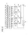
- FIG. 2 is anoverall connecting diagram of the second embodiment of the cylinder lubricating system.
- FIG.3 is a connecting diagram of the third embodiment corresponding to FIG.2.
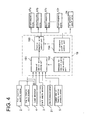
- FIG.4 is a control block diagram of the first to third embodiment.
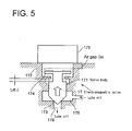
- FIG.5 is a schematic representation of the electromagnetic valve used in the first to third embodiment.
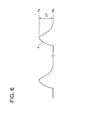
- FIG.6 is a graph for explaining the operation of the first and second embodiments.
- electromagnetic valves are provided for each of lubricators.
- reference numeral 11 are cylinder liners (cylinders) and two cylinders are shown in the drawing.
- Reference numerals 12a, 12b, 12c, ⁇ ⁇ ⁇ , 12n are lubricators for feeding lube oil to the inner surface of each cylinder 11.
- the plural lubricators 12a, 12b, 12c, ⁇ ⁇ ⁇ , 12n are located along the periphery of each cylinder 11 preferably spaced equidistantly.
- Reference numeral 14 is a lube oil pump
- 15 is a common lube oil feeding section in which lube oil pressure-fed by the lube oil pump 14 is accumulated.
- Reference numerals 16a, 16b, 16c, 16d, ⁇ ⁇ ⁇ , 16n are oil passages connecting the common lube oil feeding section 15 to the lubricators 12a, 12b, 12c, ⁇ ⁇ ⁇ , 12n of each cylinder.
- Reference numerals 17a, 17b, 17c, 17d, 17e, ⁇ ⁇ ⁇ , 17n are electromagnetic valves provided at each of the oil passages 16a, 16b, 16c, 16d, ⁇ ⁇ ⁇ , 16n respectively for opening /closing each of the passages 16a, 16b, 16c, 16d, ⁇ ⁇ ⁇ , 16n.
- each of the electromagnetic valves 17a, 17b, 17c, 17d, 17e, ⁇ ⁇ ⁇ , 17n is controlled independently by the controller 19.
- Reference numerals 18a, 18b, 18c, 18d, 18e, ⁇ ⁇ ⁇ , 18n are lube oil flow limiters, each of which are located upstream of each of the electromagnetic valves 17a, 17b, 17c, 17d, 17e, ⁇ ⁇ ⁇ , 17n which are provided to each of the oil passages 16a, 16b, 16c, 16d, ⁇ ⁇ ⁇ , 16n for opening /closing each of the oil passages 16a, 16b, 16c, 16d, ⁇ ⁇ ⁇ , 16n.
- FIG.5 is shown the structure of the electromagnetic valve 17 (17a, 17b, 17c, 17d, 17e, ⁇ ⁇ ⁇ , 17n) schematically.
- reference numeral 172 is a valve case
- 173 is a valve seat
- 171 is a valve body
- 174 is an armature fixed on the valve body 171
- 175 is a solenoid
- 176 is a valve room.
- Ga is the air gap between the undersurface of the solenoid 175 and the upper surface of the armature 174 when said lift L is at its maximum.
- Reference numeral 1 is an engine rotation speed detector for detecting the rotation speed of the engine
- 2 is a fuel injection quantity sensor for detecting the quantity of fuel injected into the cylinder
- 3 is a crank angle sensor for detecting crank angles of engine, i.e. rotation positions of the crankshaft of engine.
- Reference numeral 4 is a load detecting means by which engine load(output) is calculated from the engine rotation speed detected by said engine rotation speed detector 1 and the fuel injection quantity detected by said fuel injection quantity sensor 2.
- Reference numeral 5 is a pressure sensor for detecting the pressure in the common lube oil feeding section.
- Reference numeral 21 are oil pressure sensors for detecting the oil pressure of eachof said lubricators 12a, 12b, 12c, ⁇ ⁇ ⁇ , 12n.
- Each of the pressure sensors 21 is attached to each of the oil passages 16a, 16b, 16c, 16d, ⁇ ⁇ ⁇ 16n and detects the lube oil supply pressure of each of the lubricators 12a, 12b, 12c, ⁇ ⁇ ⁇ , 12n. It may be suitable that each of the pressure sensors 21 is provided not for eachof the oil passages 16a, 16b, 16c, 16d, ⁇ ⁇ ⁇ , 16n but one pressure sensor is provided for a plurality of the oil passages.
- the engine rotation speed detected by the engine rotation speed detector 1, the engine load detected(calculated) by the load detecting means 4, the crank angle detected by the crank angle sensor 3, the oil pressures of the lubricators 12a, 12b, 12c, ⁇ ⁇ ⁇ , 12n detected by the oil pressure sensors 21, and the oil pressure in the common lube oil feeding section detected by the pressure sensor 5 are inputted to a judging part 191(see FIG.4) of the controller 19, the judging part 191 being for judging the state of lube oil supply action.
- a plurality of said lubricators 12 are attached to one cylinder as shown by 12a, 12b, 12c, 12d, 12e, ⁇ ⁇ ⁇ , 12n, and oil passages connecting to the lubricators 12 consist of main oil passages 161, 162, 163, and 164, and branched oil passages 16a, 16b, 16c, 16d, 16e, ⁇ ⁇ ⁇ , 16n(these being corresponding to the oil passages in the first embodiment) branching from the main oil passages 161, 162, 163, and 164 to be connected to each of the lubricators 12a, 12b, 12c, 12d, 12e, ⁇ ⁇ ⁇ ,12n.
- Electromagnetic valves 17 (17A, 17B) are provided to the main oil passages 161, 162, 163, and 164 respectively so that one electromagnetic valve presides lube oil supply to a plurality of lubricators(for example, the electromagnetic valve 17A presides lube oil supply to the lubricators 12a, 12b, and 12c) in order to reduce the number of the electromagnetic valves 17.
- Reference numeral 18A is a lube oil flow limiter provided in the upstream of the electromagnetic valves 17A
- 18B is a lube oil flow limiter provided in the upstream of the electromagnetic valves 17B.
- Reference numeral 21a, 21b, 21c, 21d, 21e, ⁇ ⁇ ⁇ 21n are pressure sensors for detecting lube oil supply pressures of the lubricators 12a, 12b, 12c, ⁇ ⁇ ⁇ , 12n. These pressure sensors 21a, 21b, 21c, 21d, 21e, ⁇ ⁇ ⁇ 21n are attached to the oil passages 16a, 16b, 16c, 16d, ⁇ ⁇ ⁇ , 16n respectively to detect the lube oil supply pressure of each of the lubricators 12a, 12b, 12c, ⁇ ⁇ ⁇ , 12n respectively.
- the pressure sensors 21 may be attached to the main oil passages 161, 162, 163, and 164 as shown by dotted leader lines in FIG.2.
- the lube oil supply pressures detected by the pressure sensors 21a, 21b, 21c, 21d, 21e, ⁇ ⁇ ⁇ 21n are inputted to the state of lube oil supply action judging part 191 (see FIG. 4) of the controller 19.
- detectors and sensors shown in FIG.1 are not shown in FIG.2.
- a plurality of said lubricators 12 are attached to one cylinder as shown by 12a, 12b, 12c, 12d, 12e, ⁇ ⁇ ⁇ , 12n, and oil passages connecting to the lubricators 12 consist of main oil passages 161, 162, 163, and 164, and branched oil passages 16a, 16b, 16c, 16d, 16e, ⁇ ⁇ ⁇ , 16n(these being corresponding to the oil passages in the first embodiment) branching from the main oil passages 161, 162, 163, and 164 to be connected to each of the lubricators 12a, 12b, 12c, 12d, 12e, ⁇ ⁇ ⁇ ,12n.
- Electromagnetic valves 17 (17A, 17B, 17C, and 17D) are provided to the main oil passages 161, 162, 163, and 164 respectively so that one electromagnetic valve presides lube oil supply to a plurality of lubricators (for example, the electromagnetic valve 17A presides lube oil supply to the lubricators 12a, 12b, and 12c).
- Reference numeral 18 is a lube oil flow limiter provided in the upstream of the electromagnetic valves 17A
- 18B is a lube oil flow limiter provided in the upstream of the electromagnetic valves 17B
- 18C is a lube oil flow limiter provided in the upstream of the electromagnetic valves 17C
- 18D is a lube oil flow limiter provided in the upstream of the electromagnetic valves 17D.
- oil pressure cutoff valves 24A, 24B, 24C, and 24D are attached to the main oil passages 161, 162, 163, and 164 for shutting off the communication of the oil passages 16a, 16b, 16c, 16d, 16e, ⁇ ⁇ ⁇ , 16n to the lubricators 12a, 12b, 12c, 12d, 12e, ⁇ ⁇ ⁇ , 12n so that the main oil passages161, 162, 163, and164 canbe shutoff throughactuating the cutoff valves 24A, 24B, 24C, and 24D by control signals sent from the controller or through manual operation.
- FIG. 4 showing a control block diagram and FIG. 1 ⁇ FIG.3.
- reference numeral 192 is a reference setting part for setting the reference for lube oil supply action, in which permissible pressure differences ⁇ P are set in correspondence with engine rotation speeds or engine loads, ⁇ P being permissible pressure differences between peak values of fluctuating lube oil supply pressures and a base lube oil supply pressure, malfunction in the lube oil supply lines including the lubricators 12a, 12b, 12c, 12d, 12e, ⁇ ⁇ ⁇ , 12n and the electromagnetic valves 17(the electromagnetic valves 17a, 17b, 17c, 17d, 17e, ⁇ ⁇ ⁇ , 17n in the first embodiment shown in FIG. 1, and the electromagnetic valves 17A, 17B, 17C, and 17D in the second and third embodiment) being judged on the basis of the pressure differences.
- the pressure difference ⁇ P is defined as the difference of pressure between the peak value Pp of a fluctuating lube oil supply pressure and a base lube oil supply pressure Pb.
- permissible pressure difference ⁇ P there are set minimum permissible pressure difference P min and maximum permissible pressure difference P max in accordance with the opening period of electromagnetic valve and the oil pressure in the common lube oil feeding section, that is, with loads and rotation speeds of the engine and the the common lube oil feeding section.
- the state of lube oil supply action judging part 191 compares the pressure difference ⁇ P1 (detected pressure difference) calculated from the detected fluctuating lube oil supply pressure inputted from each of the pressure sensors 21 (21a, 21b, 21c, 21d, 21e, ⁇ ⁇ ⁇ 21n) and said minimum permissible pressure difference ⁇ P min , judges that, when the detected pressure difference ⁇ P1 is equal or smaller than the minimum permissible pressure difference ⁇ P min (when ⁇ P1 ⁇ P low ) , malfunction has occurred in the lube oil supply line to which the concerned pressure sensor 21 is attached(for example, when the detected pressure difference calculated for the pressure sensor 21a is equal or smaller than the minimum permissible pressure difference ⁇ P min , it is judged that malfunction has occurred to the lube oil supply line connecting to the lubricator 12a).
- ⁇ P1 detected pressure difference
- the judgment is sent to an electromagnetic valve control part 193 and to an oil pressure cutoff valve control part 194.
- the oil pressure cutoff valve control part 194 allows the oil pressure cutoff valve 24 of the concerned lube oil supply line to be shutoff (for example, the oil pressure cutoff valve 24A is shutoff).
- the timing and period of opening of each of the electromagnetic valves 17 for controlling lube oil supply to each of the lubricators 12a, 12b, 12c, 12d, 12e, ⁇ ⁇ ⁇ ,12n are controlled in correspondence with engine loads and rotation speeds, and malfunction in supplying lube oil judged to have occurred when the pressure difference ⁇ P1 (detected pressure difference) between the peak pressure of the fluctuating lube oil supply pressure detected by the oil pressure sensor 21 (21a, 21b, 21c, 21d, 21e, ⁇ ⁇ ⁇ 21n) and the base lube oil supply pressure ⁇ P1 is equal or smaller than the minimum permissible pressure difference ⁇ P min , so that whether abnormality has occurred in lube oil supply due to shortage in valve lift of the electromagnetic valve 17 or other factors can be judged quantitative
- the concerned oil pressure cutoff valve 24 are actuated to shutoff lube oil supply to the concerned lubricators 12 and electromagnetic valves 17 while continuing engine operation, and malfunctioning part can be repaired to restore normal function without halting the operation of the engine.
- the controller When the malfunctioning part is repaired, normal function is recovered, and a signal for releasing the actuation of the concerned oil pressure cutoff valve 24 is inputted to the controller 19, the controller allows the lube oil supply from the lubricators connected to the malfunctioning lube oil supply line to be recovered upon receiving the signal.
- the controller 19 judges whether malfunction has occurred in the electromagnetic valves 17(the electromagnetic valves 17a, 17b, 17c, 17d, 17e, ⁇ ⁇ ⁇ , 17n or the electromagnetic valves 17A, 17B, 17C, and 17D) and the lubricators12a, 12b, 12c, 12d, 12e, ⁇ ⁇ ⁇ , 12n.
- the controller 19 judges, when the period of time during which the detected lube oil supply pressure inputted from any of the oil pressure sensors 21 (21a, 21b, 21c, 21d, 21e, ⁇ ⁇ ⁇ 21n) exceeds a predetermined threshold value is longer than a permissible period of time, that malfunction has occurred in the concerned electromagnetic valve 17.
- the controller 19 judges, when any of the pressure difference ⁇ P1 (detected pressure difference) between the peak pressure Pp of the detected lube oil supply pressure inputted from any of the oil pressure sensors 21(21a, 21b, 21c, 21d, 21e, ⁇ ⁇ ⁇ , 21n) and the lube oil pressure detected by the pressure sensor 5 for detecting the pressure in the common lube oil feeding section 15 (the base lube oil pressure Pb may be used instead) is equal or larger than the maximum permissible pressure difference ⁇ P max , that malfunction has occurred in the concerned lubricator 12 among the lubricators 12a, 12b, 12c, 12d, 12e, ⁇ ⁇ ⁇ , 12n.
- ⁇ P1 detected pressure difference
- a cylinder lubricating system for an internal combustion engine capable of supplying lube oil stably in all over the operation of the engine can be provided.
- abnormality in lube oil supply can be detected for each of the electromagnetic valves and lubricators, fast recovery from the abnormality is possible, and occurrence of wear or sticking in the inner surface of cylinder due to deteriorated lubrication as a result of the abnormality of lube oil supply action can be positively evaded.
Landscapes
- Engineering & Computer Science (AREA)
- Mechanical Engineering (AREA)
- General Engineering & Computer Science (AREA)
- Lubrication Of Internal Combustion Engines (AREA)
- Combined Controls Of Internal Combustion Engines (AREA)
Applications Claiming Priority (2)
| Application Number | Priority Date | Filing Date | Title |
|---|---|---|---|
| JP2004121098 | 2004-04-16 | ||
| JP2004121098A JP4031772B2 (ja) | 2004-04-16 | 2004-04-16 | シリンダ注油装置を備えた内燃機関 |
Publications (2)
| Publication Number | Publication Date |
|---|---|
| EP1586751A2 true EP1586751A2 (fr) | 2005-10-19 |
| EP1586751A3 EP1586751A3 (fr) | 2010-03-24 |
Family
ID=34934972
Family Applications (1)
| Application Number | Title | Priority Date | Filing Date |
|---|---|---|---|
| EP05007869A Withdrawn EP1586751A3 (fr) | 2004-04-16 | 2005-04-11 | Moteur à combustion avec un dispositif de lubrification des cylindres |
Country Status (4)
| Country | Link |
|---|---|
| EP (1) | EP1586751A3 (fr) |
| JP (1) | JP4031772B2 (fr) |
| KR (1) | KR100628012B1 (fr) |
| CN (2) | CN1690374B (fr) |
Cited By (8)
| Publication number | Priority date | Publication date | Assignee | Title |
|---|---|---|---|---|
| CN101240725A (zh) * | 2007-02-06 | 2008-08-13 | 通用汽车环球科技运作公司 | 自适应油压故障检测 |
| US8911217B2 (en) | 2008-12-12 | 2014-12-16 | Toyota Jidosha Kabushiki Kaisha | Abnormality detecting device for hydraulic system |
| DK178033B1 (da) * | 2010-06-04 | 2015-03-30 | Hans Jensen Lubricators As | Hydraulisk system, fortrinsvis et centralsmøresystem til cylindersmøring |
| WO2015144182A1 (fr) * | 2014-03-25 | 2015-10-01 | Hans Jensen Lubricators A/S | Procédé et système de dosage d'huile de lubrification dans des cylindres |
| DK201670585A1 (en) * | 2016-08-05 | 2018-01-15 | Hans Jensen Lubricators As | Safety system for lubrication of the cylinder of a large slow-running internal combustion engine and a large slow-running two-stroke internal combustion engine |
| WO2019114905A1 (fr) * | 2017-12-13 | 2019-06-20 | Hans Jensen Lubricators A/S | Gros moteur à deux temps lent, procédé de lubrification de celui-ci, et injecteur doté d'un système de pompage hydraulique pas à pas pour un tel moteur et procédé |
| WO2019114903A1 (fr) | 2017-12-13 | 2019-06-20 | Hans Jensen Lubricators A/S | Gros moteur lent à deux temps et procédé de lubrification d'un tel moteur, injecteur pour un tel moteur et procédé associé, et système de soupape et son utilisation |
| WO2019114902A1 (fr) * | 2017-12-13 | 2019-06-20 | Hans Jensen Lubricators A/S | Gros moteur à deux temps lent, procédé de lubrification de celui-ci, dispositif de commande pour un tel moteur et procédé |
Families Citing this family (11)
| Publication number | Priority date | Publication date | Assignee | Title |
|---|---|---|---|---|
| JP4031772B2 (ja) | 2004-04-16 | 2008-01-09 | 三菱重工業株式会社 | シリンダ注油装置を備えた内燃機関 |
| KR100732957B1 (ko) * | 2007-03-16 | 2007-06-28 | 용원기계공업(주) | 죠크라셔 |
| JP4913029B2 (ja) * | 2007-12-27 | 2012-04-11 | 株式会社金山精機製作所 | 潤滑油供給システム |
| US8499738B2 (en) * | 2010-03-01 | 2013-08-06 | GM Global Technology Operations LLC | Control systems for a variable capacity engine oil pump |
| KR101199091B1 (ko) * | 2010-08-31 | 2012-11-08 | 기아자동차주식회사 | 엔진 유압 및 유량 제어 시스템 및 그의 제어 방법 |
| DK177258B1 (da) * | 2011-03-18 | 2012-08-27 | Hans Jensen Lubricators As | Doseringssystem for cylindersmøreolie til store cylindre samt fremgangsmåde til dosering af cylindersmøreolie til store cylindre |
| US8739746B2 (en) * | 2012-01-31 | 2014-06-03 | Ford Global Technologies, Llc | Variable oil pump diagnostic |
| JP6109485B2 (ja) * | 2012-03-16 | 2017-04-05 | 三菱重工業株式会社 | シリンダ注油装置 |
| CN102852586B (zh) * | 2012-09-26 | 2015-05-27 | 浙江吉利汽车研究院有限公司杭州分公司 | 汽车发动机机油压力监控方法 |
| CN103470335B (zh) * | 2013-09-30 | 2015-07-29 | 南安市丰州高捷摩托车节能实用科技产品销售中心 | 智能控制汽缸的润滑装置 |
| DE102017001913A1 (de) * | 2017-02-28 | 2018-08-30 | Man Truck & Bus Ag | Verfahren zur Bewertung der Schmierung einer mittels eines Schmiermittel-Kreislaufs schmierbaren Einrichtung |
Citations (1)
| Publication number | Priority date | Publication date | Assignee | Title |
|---|---|---|---|---|
| JPS59175619U (ja) | 1983-05-12 | 1984-11-24 | 三菱重工業株式会社 | シリンダ注油装置 |
Family Cites Families (13)
| Publication number | Priority date | Publication date | Assignee | Title |
|---|---|---|---|---|
| ES506543A0 (es) * | 1980-10-04 | 1982-08-16 | British Petroleum Co | Un sistema lubricante para un cilindro de motor de combus- tion interna |
| AU565950B2 (en) * | 1982-01-16 | 1987-10-01 | Ebara Corporation | Pressure control valve and oil supply device using said valve |
| JPH0784843B2 (ja) | 1986-12-25 | 1995-09-13 | マツダ株式会社 | エンジンの制御装置 |
| DK171974B1 (da) * | 1988-11-01 | 1997-09-01 | Mitsubishi Heavy Ind Ltd | Smøreaggregat til en cylinder i en forbrændingsmotor |
| DE9115265U1 (de) * | 1991-12-09 | 1993-04-08 | Joseph Vögele AG, 6800 Mannheim | Vorrichtung zum Schmieren von Zylindern |
| JPH0861592A (ja) * | 1994-08-11 | 1996-03-08 | Mitsubishi Heavy Ind Ltd | シリンダ注油装置 |
| DK173288B1 (da) * | 1996-10-11 | 2000-06-13 | Man B & W Diesel As | Cylindersmøreenhed til en flercylindret forbrændingsmotor, og fremgangsmåde til styring af leveringsmængden fra en cylinder |
| DK173533B1 (da) | 1999-01-18 | 2001-02-05 | Man B & W Diesel As | Fremgangsmåde til smøring af en cylinder i en forbrændingsmotor samt cylindersmøresystem og tilslutningselement |
| DE19959309A1 (de) * | 1999-12-09 | 2001-06-21 | Man B & W Diesel As Kopenhagen | Motor |
| DE19959300A1 (de) * | 1999-12-09 | 2001-06-21 | Man B & W Diesel As Kopenhagen | Motor |
| JP2001317320A (ja) * | 2000-05-09 | 2001-11-16 | Honda Motor Co Ltd | 内燃機関の潤滑装置 |
| JP4657523B2 (ja) | 2000-08-30 | 2011-03-23 | 本田技研工業株式会社 | 船舶用内燃機関の油圧異常警告装置 |
| JP4031772B2 (ja) | 2004-04-16 | 2008-01-09 | 三菱重工業株式会社 | シリンダ注油装置を備えた内燃機関 |
-
2004
- 2004-04-16 JP JP2004121098A patent/JP4031772B2/ja not_active Expired - Lifetime
-
2005
- 2005-04-11 EP EP05007869A patent/EP1586751A3/fr not_active Withdrawn
- 2005-04-14 KR KR1020050030923A patent/KR100628012B1/ko not_active Expired - Fee Related
- 2005-04-18 CN CN2005100762631A patent/CN1690374B/zh not_active Expired - Fee Related
- 2005-04-18 CN CN2007101028292A patent/CN101054914B/zh not_active Expired - Fee Related
Patent Citations (1)
| Publication number | Priority date | Publication date | Assignee | Title |
|---|---|---|---|---|
| JPS59175619U (ja) | 1983-05-12 | 1984-11-24 | 三菱重工業株式会社 | シリンダ注油装置 |
Cited By (19)
| Publication number | Priority date | Publication date | Assignee | Title |
|---|---|---|---|---|
| CN101240725B (zh) * | 2007-02-06 | 2013-01-02 | 通用汽车环球科技运作公司 | 自适应油压故障检测 |
| CN101240725A (zh) * | 2007-02-06 | 2008-08-13 | 通用汽车环球科技运作公司 | 自适应油压故障检测 |
| US8911217B2 (en) | 2008-12-12 | 2014-12-16 | Toyota Jidosha Kabushiki Kaisha | Abnormality detecting device for hydraulic system |
| DK178033B1 (da) * | 2010-06-04 | 2015-03-30 | Hans Jensen Lubricators As | Hydraulisk system, fortrinsvis et centralsmøresystem til cylindersmøring |
| EP2961951B2 (fr) † | 2014-03-25 | 2019-10-23 | Hans Jensen Lubricators A/S | Procédé et système de dosage d'huile de lubrification dans des cylindres |
| WO2015144182A1 (fr) * | 2014-03-25 | 2015-10-01 | Hans Jensen Lubricators A/S | Procédé et système de dosage d'huile de lubrification dans des cylindres |
| EP2961951A4 (fr) * | 2014-03-25 | 2016-02-24 | Hans Jensen Lubricators As | Procédé et système de dosage d'huile de lubrification dans des cylindres |
| KR20160134846A (ko) * | 2014-03-25 | 2016-11-23 | 한스 옌젠 루브리케이터스 에이/에스 | 실린더에 윤활유를 투여하는 방법 및 시스템 |
| EP2961951B1 (fr) | 2014-03-25 | 2016-11-30 | Hans Jensen Lubricators A/S | Procédé et système de dosage d'huile de lubrification dans des cylindres |
| KR102216353B1 (ko) | 2014-03-25 | 2021-02-17 | 한스 옌젠 루브리케이터스 에이/에스 | 실린더에 윤활유를 투여하는 방법 및 시스템 |
| DK201670585A1 (en) * | 2016-08-05 | 2018-01-15 | Hans Jensen Lubricators As | Safety system for lubrication of the cylinder of a large slow-running internal combustion engine and a large slow-running two-stroke internal combustion engine |
| DK179182B1 (en) * | 2016-08-05 | 2018-01-15 | Hans Jensen Lubricators As | Safety system for lubrication of the cylinder of a large slow-running internal combustion engine and a large slow-running two-stroke internal combustion engine |
| WO2019114903A1 (fr) | 2017-12-13 | 2019-06-20 | Hans Jensen Lubricators A/S | Gros moteur lent à deux temps et procédé de lubrification d'un tel moteur, injecteur pour un tel moteur et procédé associé, et système de soupape et son utilisation |
| WO2019114902A1 (fr) * | 2017-12-13 | 2019-06-20 | Hans Jensen Lubricators A/S | Gros moteur à deux temps lent, procédé de lubrification de celui-ci, dispositif de commande pour un tel moteur et procédé |
| WO2019114905A1 (fr) * | 2017-12-13 | 2019-06-20 | Hans Jensen Lubricators A/S | Gros moteur à deux temps lent, procédé de lubrification de celui-ci, et injecteur doté d'un système de pompage hydraulique pas à pas pour un tel moteur et procédé |
| CN111479987A (zh) * | 2017-12-13 | 2020-07-31 | 汉斯延森注油器公司 | 一种大型低速二冲程发动机及其润滑方法,以及用于这种发动机和方法的具有液压驱动泵送系统的喷射器 |
| KR20200096304A (ko) | 2017-12-13 | 2020-08-11 | 한스 옌젠 루브리케이터스 에이/에스 | 대형 저속 동작 2 행정 엔진의 윤활을 위한 밸브 시스템 및 그 사용방법 |
| KR20200096291A (ko) | 2017-12-13 | 2020-08-11 | 한스 옌젠 루브리케이터스 에이/에스 | 대형 저속 동작 2 행정 엔진 및 그 엔진을 윤활하는 방법, 그 엔진 및 방법을 위한 윤활제 인젝터 및 그 사용방법 |
| EP3910169A1 (fr) | 2017-12-13 | 2021-11-17 | Hans Jensen Lubricators A/S | Système de soupape et son utilisation |
Also Published As
| Publication number | Publication date |
|---|---|
| CN1690374B (zh) | 2010-06-16 |
| KR20060045690A (ko) | 2006-05-17 |
| CN101054914A (zh) | 2007-10-17 |
| CN101054914B (zh) | 2011-11-23 |
| KR100628012B1 (ko) | 2006-09-26 |
| JP2005299616A (ja) | 2005-10-27 |
| EP1586751A3 (fr) | 2010-03-24 |
| CN1690374A (zh) | 2005-11-02 |
| JP4031772B2 (ja) | 2008-01-09 |
Similar Documents
| Publication | Publication Date | Title |
|---|---|---|
| EP1586751A2 (fr) | Moteur à combustion avec un dispositif de lubrification des cylindres | |
| US4499876A (en) | Fuel injection control for internal combustion engines | |
| JP3806398B2 (ja) | シリンダ注油装置 | |
| US10677117B2 (en) | Oil supply device for internal combustion engine | |
| EP1927744B1 (fr) | Appareil d'injection de carburant pour moteur et procédé de fonctionnement du moteur équipé de l'appareil | |
| US8245684B2 (en) | Method of oil pressure control in an engine | |
| JP4305394B2 (ja) | 内燃機関用燃料噴射装置 | |
| JP4093696B2 (ja) | 燃料噴射装置の減圧調整弁 | |
| US20170350304A1 (en) | Piston cooling device | |
| FR2746852A1 (fr) | Procede pour reconnaitre des derangements dans le fonctionnement d'un systeme d'injection de carburant | |
| JP4930454B2 (ja) | 燃料供給制御装置およびそれを用いた燃料供給システム | |
| CN103958872A (zh) | 燃料系统控制 | |
| JP2017512937A (ja) | シリンダに潤滑油を注油する方法及びシステム | |
| US10337439B2 (en) | Control method for controlling a fuel injection system, and fuel injection system | |
| GB2320287A (en) | Controller for an injection system for a multi-cylinder internal combustion engine | |
| CN108291462B (zh) | 压力调节排布结构和方法以及润滑系统 | |
| GB2466274A (en) | A lubrication system with a variable displacement oil pump and control method therefore | |
| EP3377738B1 (fr) | Agencement et procédé de régulation de pression | |
| JP4484604B2 (ja) | エンジンの燃料噴射量制御方法およびこれを用いたエンジン運転状態判別方法 | |
| US20160230694A1 (en) | Hybrid Fuel Injection Equipment | |
| US20040101420A1 (en) | Solenoid regulated pump assembly | |
| JP5246003B2 (ja) | 燃料供給制御装置およびそれを用いた燃料供給システム | |
| JP2012092696A (ja) | 油圧駆動可変動弁機構のフェイルセーフ制御装置 | |
| JPS606579Y2 (ja) | 内燃機関の給油装置 | |
| KR20240129366A (ko) | 터보차져 파울링 방지 시스템을 위한 엔진의 크랭크케이스 압력 제어 방법 |
Legal Events
| Date | Code | Title | Description |
|---|---|---|---|
| PUAI | Public reference made under article 153(3) epc to a published international application that has entered the european phase |
Free format text: ORIGINAL CODE: 0009012 |
|
| 17P | Request for examination filed |
Effective date: 20050411 |
|
| AK | Designated contracting states |
Kind code of ref document: A2 Designated state(s): AT BE BG CH CY CZ DE DK EE ES FI FR GB GR HU IE IS IT LI LT LU MC NL PL PT RO SE SI SK TR |
|
| AX | Request for extension of the european patent |
Extension state: AL BA HR LV MK YU |
|
| PUAL | Search report despatched |
Free format text: ORIGINAL CODE: 0009013 |
|
| AK | Designated contracting states |
Kind code of ref document: A3 Designated state(s): AT BE BG CH CY CZ DE DK EE ES FI FR GB GR HU IE IS IT LI LT LU MC NL PL PT RO SE SI SK TR |
|
| AX | Request for extension of the european patent |
Extension state: AL BA HR LV MK YU |
|
| AKX | Designation fees paid |
Designated state(s): CH DE DK LI |
|
| 17Q | First examination report despatched |
Effective date: 20101123 |
|
| STAA | Information on the status of an ep patent application or granted ep patent |
Free format text: STATUS: THE APPLICATION IS DEEMED TO BE WITHDRAWN |
|
| 18D | Application deemed to be withdrawn |
Effective date: 20161214 |