EP1586747A1 - Hydraulisches Ventilspielausgleichselement - Google Patents
Hydraulisches Ventilspielausgleichselement Download PDFInfo
- Publication number
- EP1586747A1 EP1586747A1 EP05006860A EP05006860A EP1586747A1 EP 1586747 A1 EP1586747 A1 EP 1586747A1 EP 05006860 A EP05006860 A EP 05006860A EP 05006860 A EP05006860 A EP 05006860A EP 1586747 A1 EP1586747 A1 EP 1586747A1
- Authority
- EP
- European Patent Office
- Prior art keywords
- closing body
- valve
- cap
- rshva
- valve closing
- Prior art date
- Legal status (The legal status is an assumption and is not a legal conclusion. Google has not performed a legal analysis and makes no representation as to the accuracy of the status listed.)
- Granted
Links
- RTAQQCXQSZGOHL-UHFFFAOYSA-N Titanium Chemical compound [Ti] RTAQQCXQSZGOHL-UHFFFAOYSA-N 0.000 claims abstract description 3
- 239000000919 ceramic Substances 0.000 claims abstract description 3
- 229910052719 titanium Inorganic materials 0.000 claims abstract description 3
- 239000010936 titanium Substances 0.000 claims abstract description 3
- 238000007789 sealing Methods 0.000 claims description 30
- 230000006835 compression Effects 0.000 claims description 8
- 238000007906 compression Methods 0.000 claims description 8
- 125000006850 spacer group Chemical group 0.000 claims description 8
- 238000002485 combustion reaction Methods 0.000 claims description 5
- 238000000034 method Methods 0.000 claims description 5
- 229910000831 Steel Inorganic materials 0.000 claims description 2
- 239000010959 steel Substances 0.000 claims description 2
- 238000006073 displacement reaction Methods 0.000 abstract description 2
- 230000008901 benefit Effects 0.000 description 6
- 239000012530 fluid Substances 0.000 description 5
- 238000005553 drilling Methods 0.000 description 4
- 230000002706 hydrostatic effect Effects 0.000 description 4
- 238000004519 manufacturing process Methods 0.000 description 3
- 230000000694 effects Effects 0.000 description 2
- 230000009471 action Effects 0.000 description 1
- 230000005540 biological transmission Effects 0.000 description 1
- 230000008859 change Effects 0.000 description 1
- 230000000295 complement effect Effects 0.000 description 1
- 238000010276 construction Methods 0.000 description 1
- 230000006378 damage Effects 0.000 description 1
- 238000005516 engineering process Methods 0.000 description 1
- 239000003344 environmental pollutant Substances 0.000 description 1
- 230000013011 mating Effects 0.000 description 1
- 231100000719 pollutant Toxicity 0.000 description 1
- 238000003825 pressing Methods 0.000 description 1
- 230000008569 process Effects 0.000 description 1
Images



Classifications
-
- E—FIXED CONSTRUCTIONS
- E01—CONSTRUCTION OF ROADS, RAILWAYS, OR BRIDGES
- E01D—CONSTRUCTION OF BRIDGES, ELEVATED ROADWAYS OR VIADUCTS; ASSEMBLY OF BRIDGES
- E01D19/00—Structural or constructional details of bridges
- E01D19/12—Grating or flooring for bridges; Fastening railway sleepers or tracks to bridges
- E01D19/125—Grating or flooring for bridges
-
- F—MECHANICAL ENGINEERING; LIGHTING; HEATING; WEAPONS; BLASTING
- F01—MACHINES OR ENGINES IN GENERAL; ENGINE PLANTS IN GENERAL; STEAM ENGINES
- F01L—CYCLICALLY OPERATING VALVES FOR MACHINES OR ENGINES
- F01L1/00—Valve-gear or valve arrangements, e.g. lift-valve gear
- F01L1/20—Adjusting or compensating clearance
- F01L1/22—Adjusting or compensating clearance automatically, e.g. mechanically
- F01L1/24—Adjusting or compensating clearance automatically, e.g. mechanically by fluid means, e.g. hydraulically
-
- E—FIXED CONSTRUCTIONS
- E01—CONSTRUCTION OF ROADS, RAILWAYS, OR BRIDGES
- E01D—CONSTRUCTION OF BRIDGES, ELEVATED ROADWAYS OR VIADUCTS; ASSEMBLY OF BRIDGES
- E01D2101/00—Material constitution of bridges
- E01D2101/20—Concrete, stone or stone-like material
- E01D2101/24—Concrete
- E01D2101/26—Concrete reinforced
- E01D2101/268—Composite concrete-metal
-
- F—MECHANICAL ENGINEERING; LIGHTING; HEATING; WEAPONS; BLASTING
- F01—MACHINES OR ENGINES IN GENERAL; ENGINE PLANTS IN GENERAL; STEAM ENGINES
- F01L—CYCLICALLY OPERATING VALVES FOR MACHINES OR ENGINES
- F01L2301/00—Using particular materials
-
- F—MECHANICAL ENGINEERING; LIGHTING; HEATING; WEAPONS; BLASTING
- F01—MACHINES OR ENGINES IN GENERAL; ENGINE PLANTS IN GENERAL; STEAM ENGINES
- F01L—CYCLICALLY OPERATING VALVES FOR MACHINES OR ENGINES
- F01L2301/00—Using particular materials
- F01L2301/02—Using ceramic materials
Definitions
- the invention relates to a hydraulic valve clearance compensation element for a Valve train of an internal combustion engine, in particular according to the preamble of Patent claim 1.
- Hydraulic lash adjusters serve to balance the play, This is due to wear or thermal expansion between the transmission elements the cam lift on the gas exchange valves of an internal combustion engine forms. In this way, a low-noise and low-wear valve train and the widest possible match of cam lift curve and valve lift curve can be achieved.
- Such hydraulic valve clearance compensation elements are due to the opposite conventional hydraulic lash adjusters reversed Arrangement of the closing body springs Reverse Spring hydraulic valve clearance compensation elements called and for further description with RSHVA for short.
- RSHVA's have a positive influence on thermodynamics, Pollutant emission and mechanical stress of the internal combustion engine out. Important condition for a perfect function of the RSHVA's are a constant stroke and closing pressure of the valve closing body. Thereby a constant idle stroke of the RSHVA's is achieved.
- valve body spring of the generic EP 1 298 287 A2 is designed to that the valve between the high and low pressure chamber when mounting the RSHVA allowed a fluid exchange, but with pressure increase in the high-pressure chamber closes as quickly as possible against the spring force of the valve body spring. These Spring force must therefore be relatively low. Therefore, the spherical Valve closing body offset by possible lateral flow in rotation and be displaced laterally with the valve body spring. This will be the Closing force of the valve body spring and as a result of the idle stroke of RSHVA's changed. In extreme cases, the valve body spring in the seat gap of the control valve, resulting in further variations of the Leerhubs and the Upset or even total failure of the RSHVA and destruction the valve body spring can lead.
- the invention has for its object to provide a RSHVA, the Has advantages of the solution listed in the prior art, but whose Disadvantages avoids.
- valve closing body with guide game enclosing, parallel applied to the axis of the RSHVA cylindrical guide surface the flowing during closing of the control valve fluid flow the valve control body in the closing direction. Its action is predominantly hydrostatic, so that the valve closing body is moved linearly like a piston.
- a guided valve closing body can be an unguided hydrodynamic Actuation of an ungauged valve closing body to an eccentric Position and to a rotational movement of the same with said Lead to disadvantages.
- a hydrodynamically acted valve closing body for the closing process a larger amount of oil than a hydrostatic required.
- Valve body springs can be formed as cylindrical or conical compression springs.
- valve closing body instead of steel, for example made of titanium or ceramic is.
- cylindrical guide surface offers the inside of the cylindrical center piece of the Closing cap on.
- valve closing body as a ball or as a through a circular cylindrical spacer extended ball (a so-called needle) is formed and that the Cap base a serving as stroke limitation center piece with rotationally symmetrical arranged around the same, preferably designed as bores Has openings.
- the rotationally symmetrical holes provide for a uniform, axial flow of the pressure oil to the valve closing body, which is not rotated in this way.
- a rotation about a horizontal axis is in addition to the needle through prevents the axially guided circular cylindrical intermediate piece of the same.
- valve closing body is an elongated circular cylindrical Having intermediate piece and a flattened, valve seat remote end and the closing body cap has a cap bottom with a central opening, which is preferably designed as a central bore and its edge region serves as a stroke limiter for the valve closing body.
- the axial forced operation of the valve closing body by the extended circular cylindrical spacer inevitably prevents rotation about a horizontal axis.
- valve closing body of a control valve at its valve seat remote end has an example circular cylindrical pin whose diameter corresponds to the diameter of the central bore of the closing body cap with guide clearance and whose length is greater than the stroke of the valve closing body.
- a torsion-proof construction of the valve-closing body about all axes is achieved in that it has at least one lateral, axially parallel profiling, preferably a flattening.
- the flattening offers manufacturing advantages, but also any other axially parallel cylindrical profiles are conceivable.
- valve closing body which is non-rotatable about all axes is that, in addition to its extended, circular-cylindrical intermediate piece, it has at least one eccentric, undercut-free recess which corresponds with a corresponding step of the closing body cap.
- the recess provides an anti-rotation about the longitudinal axis, while the undercut clearance is a prerequisite for the axial mobility of the valve closing body.
- the height of the control valve is reduced when the valve closing body a flat spherical cap as a sealing surface and an adjoining flattened End as a stop for the Hubbegrenzung on the cap bottom of the Has closing body cap and, if the same dish-shaped.
- Valve closing body A version secured against rotation about a horizontal axis Valve closing body is that the same a spherical shape with opposite, preferably circular cylindrical depressions, wherein the valve seat near depression of the conical valve body spring serves as a support and the valve seat remote depression with a centric guide lug of the Cap bottom corresponds and the valve closing body as a stop and Leadership serves.
- An advantageous development of the invention is that with a a cylindrical guide surface connected to a piston bottom into an underside introduced the piston crown and up to a cylindrical ring Sealing surface-reaching, concentric bore is at least the guide line or the guide surface of the valve closing body encloses with guide clearance and that a closing body cap with its cylindrical cap center piece on an outer diameter reduced end portion of the piston crown centered and a cap flange on a shoulder of the reduced End part and a cap bottom rest on the underside of the piston crown.
- the closing body cap serves the valve closing body only for stroke limitation and for even oil supply. It is also conceivable that a profiled pin on the underside of the valve closing body in conjunction with a corresponding central opening in the cap bottom a tilt protection about a horizontal axis and at the same time an anti-twist device offers around the longitudinal axis.
- An advantage for a rapid fluid exchange between the high and low pressure space is that the concentric bore of a control valve an enlarged diameter in the range from the lower end to at least to the upper end of the circular cylindrical guide surface or to the circular guide line of the voltage applied to the Hubbegrenzungs Staline Valve closing body has.
- a correspondingly designed valve body spring moves the valve closing body to its stroke limit and thus in the Range of inner diameter enlargement, the one unthrottled fluid exchange allowed between the pressure chambers.
- An advantage for a flexible and varied design of the control valves is that the management characteristics of each control valve exchange- or can be combined.
- An advantage for cost-effective mass production offers a method for Equalization of the valve lift of the valve closing body, that with the help of a Master valve closing body of the actual stroke of the control valve measured and the Sollhub is adjusted by appropriate paired valve closing body.
- Another method for equalization of the valve lift of the valve closing body is that the actual stroke of the control valve measured and the target stroke adjusted by pressing the cap bottom of the closing body cap becomes.
- the piston 1 has a piston head 2, the one below the piston. 1 in the blind hole, not shown, arranged high-pressure chamber 3 of a in the piston 1 above the piston head 2 arranged low-pressure space 4th separates.
- a control valve 5 which is one of the two pressure chambers 3 and 4 connecting central axial bore 6 dominates.
- the control valve 5 has a spherical valve closing body 7, which is between an arranged on the piston head 2, cylindrical sealing surface 8 and a Hubbegrenzungsisation 9 moves.
- the spherical valve closing body 7 and the cylindrical annular sealing surface 8 touch in one circular sealing line.
- the Hubbegrenzungs preparation 9 is part of a closing body cap 10, the one Cap flange 11, a cylindrical cap center piece 12 and a cap bottom 13 has.
- the cap base 13 has a center piece 24, the inside of the Hubbegrenzungs preparation 9 is and surrounded by evenly spaced holes 21 is.
- the cap flange 11 is located on a shoulder 14 of a concentric depression 15, which from the bottom 16 of the piston crown 2 in the same is introduced. In the recess 15 of the cap flange 11 is centered. Because the concentric depression 15 is slightly retracted, the closing body cap 10 clipped during assembly and thereby axially fixed.
- the inside of the cylindrical cap center piece 12 serves as a piston bottom fixed Guide surface 20, which is the circular guide line 40 of the spherical Includes valve closing body 7 with guide clearance.
- the shoulder 14 can also be worked deeper into the piston head 2 to the axial Distance between the piston bottom-fixed guide surface 20 and the cylindrical ring-shaped To reduce sealing surface 8 and thus the leadership of the valve closing body 7 to ensure closing of the control valve 5.
- a step 19 is formed, on which a valve body spring 17 is supported. This acts on the spherical valve closing body 7 in the opening direction.
- the spherical valve closing body 7 and its guide surface 20 may have at least one , not shown, axially parallel flattening to prevent rotation about the vertical axis.
- the piston 1 via the cap flange 11 is pressurized.
- control valve 5 functions as follows:
- the high-pressure chamber 3 is under pressure. This Also acts on the valve closing body 7, which bears against its sealing surface 8. Because of the high pressure escapes a certain amount of oil through the sealing gap between the piston 1 and the blind hole. This will do that RSHVA slightly compressed, leaving the valve gear in the subsequent Base circle phase of the cam valve clearance has. This way will the high pressure chamber 3 relieved of pressure and the piston 1 by means of the compression spring 23 moved out until the valve clearance from the blind hole. As a result, a negative pressure is formed in the high-pressure chamber 3. Through this and by the spring force of the valve body spring 17, the valve closing body 7 in Direction Hubbegrenzungs character 9 moves. This clears the way for the oil flow, from the low-pressure chamber 4 through the holes 6 and 18 between the valve closing body 7 and the guide surface 20 and by the Holes 21 passes into the high-pressure chamber 3.
- the control valve 5 must first by moving of the spherical valve closing body 7 are closed. This happens by displacing a small amount of oil through the holes 21, whereby the valve closing body 7 hydrostatically uniformly opposed as a piston the spring force of the valve body spring 17 moves against the sealing surface 8 becomes.
- the guide surface 20 prevents a lateral displacement of the spherical Valve closing body 7, wherein the uniform, hydrostatic Also, apply the same to a horizontal or horizontal rotation vertical axis prevented. This effect can also be caused by lateral flattening the spherical valve closing body 7 and the matching Guide surface 20 are supported.
- the inventive design of the control valve 5 is a change the closing forces of the valve closing body 7 and thus a variation of Idle strokes of the RSHVA avoided.
- FIGS. 2 to 8 the concept presented in FIG. 1 is changed on the valve closing body and the associated closing body cap or guide surface modified.
- a control valve 5a with a Valve closing body 7a shown as a through a circular cylindrical spacer 25 elongated ball (a so-called needle) is formed.
- a closing body cap 10a largely corresponds to the closing body cap 10 of FIG. 1.
- the closing body cap 10a also has a cap base 13 with a center piece 24 as a stroke limiter, that of holes 21 is surrounded.
- the control valve 5b shown in Figure 3 has a valve closing body 7b with an elongated, circular cylindrical intermediate piece 29 and a flattened, valve seat removed end 26.
- a closing body cap 10b has a central bore 27 in the cap bottom 13b, the edge region as a stroke limiter for the valve closing body 7b serves.
- the central bore 27 also ensures uniform loading of the valve closing body by the effluent from the high-pressure chamber 3 Oil.
- the valve closing body 7b is by a forced longitudinal guide characterized.
- Figure 4 illustrates a control valve 5c, the valve closing body 7c to the difference to Figure 3 at its valve seat remote end 26a a circular cylindrical Pin 28, whose diameter with guide clearance the diameter a central bore 27a of the closing body cap 10c and its Length is greater than the stroke of the valve closing body 5c.
- the circular cylindrical Adapter 29 and the circular cylindrical pin 28 serve the forcibly longitudinal guide of the valve closing body 7c.
- complementary Profiling of the pin 28 and the central bore 27 a may be an additional Anti-rotation of the valve closing body 7c about its longitudinal axis be achieved.
- FIG. 5 shows a control valve 5d whose valve closing body 7d is in the region of its extended circular cylindrical intermediate piece 29 a lateral, paraxial Flattening 30, the mating surface on the inner circumference of the Cap center piece 12a of the closing body cap 10d is arranged.
- the number of course, the flattening can be larger, with two offer opposite manufacturing technology. All serve to prevent a rotation of the valve closing body 7d about its longitudinal axis and about horizontal Axes.
- FIG. 6 shows a control valve 5e whose valve closing body 7e has an eccentric, undercut-free recess 31, which cooperates with a corresponding step 32 of the closing body flap 10e.
- the recess 31 prevents, in conjunction with the step 32, a rotation of the valve closing body 7e about its longitudinal axis, the circular cylindrical, extended intermediate piece 29 thereof tilting.
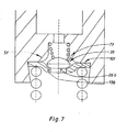
- Figure 7 shows a control valve 5f with a valve closing body 7f, which has a flat Kugelkalotte 33 as a sealing surface and an adjoining, flattened Valve seat remote end 26b as a stop for the stroke limitation on the cap base 13a of the closing body cap 10f.
- the flat, plate-shaped closing body cap 10f together with the shortest, low-profile valve closing body, makes it possible 7f a small height of the control valve 5f.
- FIG. 8 shows a control valve 5g with a valve closing body 7g, the one spherical shape with opposite circular cylindrical depressions 34, 34a.
- the valve seat near recess 34 serves the conical valve body spring 17a as a support
- the valve seat remote recess 34a with a centric guide lug 35 of a cap bottom 13c of a closing body cap 10g cooperates, serves the valve closing body 7g as a stop and complicates its rotation about the longitudinal axis.
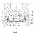
- FIG. 9 shows a control valve 5h with a spherical valve closing body 7, which is guided in a central and axially parallel bore 36 which in a Bottom 16a of a piston crown 2a is introduced.
- Cylindrical and axially parallel guide surface 20a serves here, the inner surface the bore 36, the spherical valve closing body 7 with guide play encloses.
- the bore 36 extends to a cylindrical annular sealing surface 8a of the piston crown 2a.
- Guide line 40 is guided axially parallel to the contact with the sealing surface 8a and prevented from rotating.
- a closing body cap 10h is with its cylindrical cap center piece 12b on an outer diameter reduced end portion 37 of the piston crown 2a centered.
- a cap flange 11 a is under the pressure of a high-pressure chamber 3 arranged compression spring 23 a on a shoulder 38 of the reduced End portion 37, while a cap bottom 13c on the underside 16a of the piston crown 2a rests.
- a centric, surrounded by holes 21 a center piece 24a with a Hubbegrenzungs constitutional 9 serves the valve closing body 7 as stroke limitation.
- control valve 5h corresponds to that described above Control valve 5 of Figure 1.
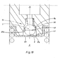
- FIG 10 shows a control valve 5i, the valve closing body 7 at the Hubbegrenzungs constitutional 9 abuts and the bore 36a is in the range of lower end 39 to the upper end of the circular cylindrical guide surface 25, 29 of the valve closing body 7a, 7b (see Figure 2 + 3) or to the circular Guide line 40 of the valve closing body 7 has an expanded inner diameter 41 has.
- the illustrated position of the valve closing body 7 is due to the cross-sectional widening of the bore 36 is a largely undisturbed Mass transfer between the high and the low pressure space 3, 4 along the valve closing body 7 instead.
- the drive of the valve closing body 7 is effected by the uniform Inflow of oil from the high-pressure chamber 3 via the holes 21 a at the beginning of the cam lift until the closing of the control valve 5i.
- the uniform loading of the spherical valve closing body 7 prevented a rotational movement of the same and leads to a rapid closing of the control valve 5i.
Landscapes
- Engineering & Computer Science (AREA)
- Mechanical Engineering (AREA)
- General Engineering & Computer Science (AREA)
- Architecture (AREA)
- Civil Engineering (AREA)
- Structural Engineering (AREA)
- Lift Valve (AREA)
- Valve-Gear Or Valve Arrangements (AREA)
Abstract
Description
- ein Gehäuse eines Ventilspielausgleichselements weist eine Sackbohrung auf, in der ein Kolben mit Dichtspiel geführt ist;
- der Kolben weist einen Kolbenboden auf, der zusammen mit der Sackbohrung einen Hochdruckraum begrenzt, während sich oberhalb des Kolbenbodens ein Niederdruckraum befindet;
- die Druckräume sind durch eine zentrische Axialöffnung im Kolbenboden verbunden, die durch ein auf der Unterseite des Kolbenbodens angeordnetes Steuerventil beherrscht ist;
- das Steuerventil besitzt einen Ventilschließkörper, der eine halbkugelförmige Dichtfläche aufweist, die zusammen mit einer am Kolbenboden angeordneten zylinderringförmigen Dichtfläche eine kreisförmige Dichtlinie bildet;
- eine Ventilkörperfeder die sich auf einer Stufe zwischen der zentrischen Axialbohrung und einer unterhalb der selben befindlichen koaxialen Bohrung abstützt, beaufschlagt den Ventilschließkörper in Öffnungsrichtung, während Überdruck im Hochdruckraum den Ventilschließkörper in Schließrichtung beaufschlagt;
- eine Schließkörperkappe besitzt einen Kappenflansch, ein im wesentlichen zylindrisches Kappenmittenstück und einen mit mindestens einer Öffnung versehenen Kappenboden;
- die Schließkörperkappe ist am Kolbenboden abgestützt und zentriert und dient dem Ventilschließkörper als Hubbegrenzung;
- der Kolben ist über den Kappenflansch von einer im Hochdruckraum angeordneten Druckfeder druckbeaufschlagt.
Dadurch ist während des gesamten Hubs desselben eine exakte axiale Führung gewährleistet.
- Figur 1
- einen Längsschnitt durch einen unteren Teil eines Kolbens mit einem Kolbenboden, einem Steuerventil, einem als Kugel ausgebildeten Ventilschließkörper und einem mehrere Bohrungen aufweisenden Kappenboden;
- Figur 2
- einen Längsschnitt wie in Figur 1, jedoch als Ventilschließkörper eine durch ein kreiszylindrisches Zwischenstück verlängerte Kugel;
- Figur 3
- einen Längsschnitt wie in Figur 2, jedoch ein verlängertes, kreiszylindrisches Zwischenstück und ein abgeflachtes Ende sowie einen Kappenboden mit einer zentralen Bohrung;
- Figur 4
- einen Längsschnitt wie Figur 3, jedoch weist der Ventilschließkörper an seinem ventilsitzfernen Ende einen kreiszylindrischen Zapfen auf, dessen Durchmesser mit Führungsspiel dem Durchmesser der zentralen Bohrung entspricht;
- Figur 5
- einen Längsschnitt wie Figur 3, jedoch weist der Ventilschließkörper eine seitliche achsparallel verlaufende Anflachung auf;
- Figur 6
- einen Längsschnitt wie Figur 3, jedoch mit einem Ventilschließkörper, der eine exzentrische, nach unten hinterschnittfreie Aussparung aufweist;
- Figur 7
- einen Längsschnitt wie Figur 3, jedoch mit einem Steuerventil, dessen Ventilschließkörper eine flache Kugelkalotte aufweist und dessen Schließkörperkappe tellerförmig gestaltet ist;
- Figur 8
- einen Längsschnitt wie Figur 1, jedoch mit einem Ventilschließkörper, der gegenüberliegende, zylindrische Einsenkungen für eine Ventilkörperfeder und eine Führungsnase des Kappenbodens aufweist;
- Figur 9
- einen Längsschnitt durch einen Kolbenboden mit einem Steuerventil, dessen mit dem Kolbenboden verbundene Führungsfläche die Oberfläche einer von unten in den Kolbenboden eingebrachten zentralen Bohrung ist;
- Figur 10
- einen Längsschnitt wie Figur 9, jedoch mit einer Durchmesservergrößerung der konzentrischen Bohrung, die vom unteren Ende derselben bis zum oberen Ende der zylindrischen Führungsfläche des an der Hubbegrenzung anliegenden Ventilschließkörpers reicht.
- 1
- Kolben
- 2
- Kolbenboden
- 2a
- Kolbenboden
- 3
- Hochdruckraum
- 4
- Niederdruckraum
- 5
- Steuerventil
- 5a
- Steuerventil
- 5b
- Steuerventil
- 5c
- Steuerventil
- 5d
- Steuerventil
- 5e
- Steuerventil
- 5f
- Steuerventil
- 5g
- Steuerventil
- 5h
- Steuerventil
- 5i
- Steuerventil
- 6
- zentrische Axialbohrung
- 7
- Ventilschließkörper
- 7a
- Ventilschließkörper
- 7b
- Ventilschließkörper
- 7c
- Ventilschließkörper
- 7d
- Ventilschließkörper
- 7e
- Ventilschließkörper
- 7f
- Ventilschließkörper
- 7g
- Ventilschließkörper
- 8
- zylinderringförmige Dichtfläche
- 8a
- zylinderringförmige Dichtfläche
- 9
- Hubbegrenzungsfläche
- 10
- Schließkörperkappe
- 10a
- Schließkörperkappe
- 10b
- Schließkörperkappe
- 10c
- Schließkörperkappe
- 10d
- Schließkörperkappe
- 10e
- Schließkörperkappe
- 10f
- Schließkörperkappe
- 10g
- Schließkörperkappe
- 10h
- Schließkörperkappe
- 11
- Kappenflansch
- 11a
- Kappenflansch
- 12
- Kappenmittenstück
- 12a
- Kappenmittenstück
- 12b
- Kappenmittenstück
- 13
- Kappenboden
- 13a
- Kappenboden
- 13b
- Kappenboden
- 13c
- Kappenboden
- 13d
- Kappenboden
- 14
- Schulter
- 15
- konzentrische Bohrung
- 16
- Unterseite
- 16a
- Unterseite
- 17
- Ventilkörperfeder
- 17a
- Ventilkörperfeder
- 18
- koaxiale Axialbohrung
- 19
- Stufe
- 20
- kolbenbodenfeste Führungsfläche
- 20a
- kolbenbodenfeste Führungsfläche
- 21
- Bohrung
- 21a
- Bohrung
- 22
- Unterseite
- 23
- Druckfeder
- 23a
- Druckfeder
- 24
- Mittenstück
- 24a
- Mittenstück
- 25
- kreiszylindrisches Zwischenstück
- 26
- ventilsitzfernes Ende
- 26a
- ventilsitzfernes Ende
- 26b
- ventilsitzfernes Ende
- 27
- zentrale Bohrung
- 27a
- zentrale Bohrung
- 28
- kreiszylindrischer Zapfen
- 29
- verlängertes kreiszylindrisches Zwischenstück
- 30
- Anflachung
- 31
- Aussparung
- 32
- Stufe
- 33
- flache Kugelkalotte
- 34
- Einsenkung
- 34a
- Einsenkung
- 35
- Führungsnase
- 36
- Bohrung
- 36a
- Bohrung
- 37
- Endteil
- 38
- Schulter
- 39
- unteres Ende
- 40
- Führungslinie
- 41
- Innendurchmesser
Claims (17)
- RSHVA für den Ventiltrieb eines Verbrennungsmotors, das durch folgende Merkmale gekennzeichnet ist:ein Gehäuse eines Ventilspielausgleichselements weist eine Sackbohrung auf, in der ein Kolben (1) mit Dichtspiel geführt ist;der Kolben (1) weist einen Kolbenboden (2) auf, der zusammen mit der Sackbohrung einen Hochdruckraum (3) begrenzt, während sich oberhalb des Kolbenbodens (2) ein Niederdruckraum (4) befindet;die Druckräume (3, 4) sind durch eine zentrische Axialöffnung (6) im Kolbenboden (2) verbunden, die durch ein auf der Unterseite des Kolbenbodens (2) angeordnetes Steuerventil (5) beherrscht ist;das Steuerventil (5) besitzt einen Ventilschließkörper (7), der eine halbkugelförmige Dichtfläche aufweist, die zusammen mit einer am Kolbenboden (2) angeordneten zylinderringförmigen Dichtfläche (8) eine kreisförmige Dichtlinie bildet;eine Ventilkörperfeder (17), die sich auf einer Stufe (19) zwischen der zentrischen Axialbohrung (6) und der unterhalb der selben befindlichen Dichtfläche (8) abstützt, beaufschlagt den Ventilschließkörper (7) in Öffnungsrichtung, während ein Überdruck im Hochdruckraum (3) den Ventilschließkörper (7) in Schließrichtung beaufschlagt;eine Schließkörperkappe (10) besitzt einen Kappenflansch (11) ein im Wesentlichen zylindrisches Kappenmittenstück (12) und einen mit Öffnungen (21) versehenen Kappenboden (13);die Schließkörperkappe (10) ist am Kolbenboden (2) abgestützt und zentriert und der Kappenboden (13) dient dem Ventilschließkörper (7) als Hubbegrenzung;der Kolben (1) ist über den Kappenflansch (11) von einer im Hochdruckraum (3) angeordneten Druckfeder (23) druckbeaufschlagt, dadurch gekennzeichnet, dass eine mit einem Kolbenboden (2, 2a) verbundene, zylindrische und achsparallele Führungsfläche (20, 20a) vorgesehen ist, die eine entsprechende Führungslinie (40) bzw. Führungsfläche (25, 29, 30) eines Ventilschließkörpers (7, 7a, 7b, 7c, 7d, 7e, 7f, 7g) mit Führungsspiel umschließt.
- RSHVA nach Anspruch 1, dadurch gekennzeichnet, dass die Ventilkörperfedern (17, 17a) als zylindrische oder konische Druckfedern ausbildbar sind.
- RSHVA nach Anspruch 2, dadurch gekennzeichnet, dass der Ventilschließkörper (7, 7a, 7b, 7c, 7d, 7e, 7f, 7g) anstelle aus Stahl beispielsweise aus Titan oder Keramik gefertigt ist.
- RSHVA nach Anspruch 3, dadurch gekennzeichnet, dass die mit dem Kolbenboden (2) verbundene, zylindrische Führungsfläche (20, 20a) die Innenseite des zylindrischen Kappenmittenstücks (12, 12a, 12b) der Schließkörperkappe (10, 10a, 10b, 10c, 10d, 10e, 10f, 10g) ist.
- RSHVA nach Anspruch 4, dadurch gekennzeichnet, dass die Unterseite (16) des Kolbenbodens (2) eine bis zu der zylinderringförmigen Dichtungsfläche (8) reichende konzentrische Bohrung (15) aufweist, die eine Schulter (14) besitzt, auf der der Kappenflansch (11) ruht, der in der Bohrung (15) zentriert ist.
- RSHVA nach Anspruch 5, dadurch gekennzeichnet, dass der Ventilschließkörper (7, 7a) eines Steuerventils (5, 5a) als Kugel oder als Kugel mit mindestens einer achsparallelen Anflachung oder als eine durch ein kreiszylindrisches Zwischenstück (25) verlängerte Kugel (eine so genannte Nadel) ausgebildet ist und dass der Kappenboden (13) ein als Hubbegrenzung dienendes Mittenstück (24) mit drehsymmetrisch um das selbe angeordnete, vorzugsweise als Bohrungen (21) ausgebildete Öffnungen aufweist.
- RSHVA nach Anspruch 5, dadurch gekennzeichnet, dass der Ventilschließkörper (7b) eines Steuerventils (5b) ein verlängertes kreiszylindrisches Zwischenstück (29) und ein abgeflachtes, ventilsitzfernes Ende (26) aufweist und die Schließkörperkappe (10b) einen Kappenboden (13a) mit einer zentralen Öffnung besitzt, die vorzugsweise als zentrale Bohrung (27) ausgebildet ist und deren Randbereich als Hubbegrenzung für den Ventilschließkörper (7b) dient.
- RSHVA nach Anspruch 7, dadurch gekennzeichnet, dass der Ventilschließkörper (7c) eines Steuerventils (5c) an seinem ventilsitzfernen Ende (26a) einen beispielsweise kreiszylindrischen Zapfen (28) aufweist, dessen Durchmesser mit Führungsspiel dem Durchmesser der zentralen Bohrung (27) der Schließkörperkappe (10c) entspricht und dessen Länge größer als der Hub des Ventilschließkörpers (7c) ist.
- RSHVA nach Anspruch 7, dadurch gekennzeichnet, dass der Ventilschließkörper (7d) eines Steuerventils (5d) im Bereich seines verlängerten kreiszylindrischen Zwischenstücks (29) zumindest eine seitliche, achsparallele, vorzugsweise als Anflachung (30) ausgebildete Profilierung aufweist.
- RSHVA nach Anspruch 7, dadurch gekennzeichnet, dass der Ventilschließkörper (7e) eines Steuerventils (5e) zumindest eine exzentrische nach unten hinterschnittfreie Aussparung (31) aufweist, die mit einer entsprechenden Stufe (32) der Schließkörperkappe (10e) korrespondiert.
- RSHVA nach Anspruch 5, dadurch gekennzeichnet, dass der Ventilschließkörper (7f) eine flache Kugelkalotte (33) als Dichtfläche und ein daran anschließendes, angeflachtes Ende (26b) als Anschlag für die Hubbegrenzung am Kappenboden (13b) der Schließkörperkappe (10f) aufweist und dass dieselbe tellerförmig gestaltet ist.
- RSHVA nach Anspruch 5, dadurch gekennzeichnet, dass der Ventilschließkörper (7g) eines Steuerventils (5g)eine Kugelform mit gegenüberliegenden, vorzugsweise kreiszylindrischen Einsenkungen (34, 34a) aufweist, wobei die ventilsitznahe Einsenkung (34) der konischen Ventilkörperfeder (17a) als Auflage dient und die ventilsitzferne Einsenkung (34a) mit einer zentrischen Führungsnase (35) des Kappenbodens (13c) korrespondiert und dem Ventilschließkörper (7g) als Anschlag und Führung dient.
- RSHVA nach Anspruch 3, dadurch gekennzeichnet, dass eine mit einem Kolbenboden (2a) verbundene, zylindrische Führungsfläche (20a) eine in eine Unterseite (16a) des Kolbenbodens (2a) eingebrachte und bis zu einer zylinderringförmigen Dichtfläche (8a) reichende, konzentrische Bohrung (36) ist, die zumindest die Führungslinie (40) bzw. die Führungsfläche (25, 29) des Ventilschließkörpers (7, 7a, 7b, 7c) der Steuerventile (5, 5a, 5b, 5c) mit Führungsspiel umschließt und dass eine Schließkörperkappe (10h) mit ihrem zylindrischen Kappenmittenstück (12b) auf einem im Aüßendurchmesser reduzierten Endteil (37) des Kolbenbodens (2a) zentriert ist und ein Kappenflansch (11a) an einer Schulter (38) des reduzierten Endteils (37) sowie ein Kappenboden (13d) an der Unterseite (16a) des Kappenbodens (2a) aufliegen.
- RSHVA nach Anspruch 13, dadurch gekennzeichnet, dass die konzentrische Bohrung (36) mit ihrer Führungsfläche (20a) eines Steuerventils (5i) einen vergrößerten Durchmesser (41) im Bereich von deren unteren Ende (39) bis mindestens zum oberen Ende der kreiszylindrischen Führungsfläche (25, 29) bzw. bis zur kreisförmigen Führungslinie (40) des an der Hubbegrenzungsfläche (9) anliegenden Ventilschließkörpers (7, 7a, 7b) aufweist.
- RSHVA nach Anspruch 1, dadurch gekennzeichnet, dass die führungsrelevanten Merkmale der einzelnen Steuerventile (5, 5a, 5b, 5c, 5d, 5e, 5f, 5g, 5h, 5i) austausch- bzw. kombinierbar sind.
- Verfahren zur Gleichstellung des Ventilhubs des Ventilschließkörpers (7, 7a, 7b, 7c, 7d, 7e, 7f, 7g) des RSHVA nach Anspruch 1, dadurch gekennzeichnet, dass mit Hilfe eines Master-Ventilschließkörpers der Isthub des Steuerventils (5, 5a, 5b, 5c, 5d, 5e, 5f, 5g, 5h, 5i) gemessen und der Sollhub durch entsprechende gepaarte Ventilschließkörper (7, 7a, 7b, 7c, 7d, 7e, 7f, 7g) eingestellt wird.
- Verfahren zur Gleichstellung des Ventilhubs des Ventilschaftkörpers (7, 7a-g) des RSHVA nach Anspruch 1, dadurch gekennzeichnet, dass der Isthub des Steuerventils (5, 5a-i) gemessen und der Sollhub durch Nachdrücken des Kappenbodens (13, 13a-d) der Schließkörperkappe (10, 10a-h) eingestellt wird.
Applications Claiming Priority (2)
| Application Number | Priority Date | Filing Date | Title |
|---|---|---|---|
| DE102004018457A DE102004018457A1 (de) | 2004-04-16 | 2004-04-16 | Hydraulisches Ventilspielausgleichselement |
| DE102004018457 | 2004-04-16 |
Publications (2)
| Publication Number | Publication Date |
|---|---|
| EP1586747A1 true EP1586747A1 (de) | 2005-10-19 |
| EP1586747B1 EP1586747B1 (de) | 2008-11-12 |
Family
ID=34934573
Family Applications (1)
| Application Number | Title | Priority Date | Filing Date |
|---|---|---|---|
| EP05006860A Expired - Lifetime EP1586747B1 (de) | 2004-04-16 | 2005-03-30 | Hydraulisches Ventilspielausgleichselement |
Country Status (6)
| Country | Link |
|---|---|
| US (1) | US7146954B2 (de) |
| EP (1) | EP1586747B1 (de) |
| JP (1) | JP2005325835A (de) |
| KR (1) | KR20060045750A (de) |
| CN (1) | CN1683755B (de) |
| DE (2) | DE102004018457A1 (de) |
Cited By (3)
| Publication number | Priority date | Publication date | Assignee | Title |
|---|---|---|---|---|
| EP1701007A1 (de) * | 2005-03-09 | 2006-09-13 | Schaeffler KG | Hydraulisches Ventilspielausgleichselement |
| EP1967704A1 (de) * | 2007-03-09 | 2008-09-10 | Otics Corporation | Spielausgleichselement |
| EP2256308B1 (de) * | 2008-02-13 | 2016-04-13 | OTICS Corporation | Spielausgleichselement |
Families Citing this family (16)
| Publication number | Priority date | Publication date | Assignee | Title |
|---|---|---|---|---|
| US20070272185A1 (en) * | 2006-05-24 | 2007-11-29 | Schaeffler Kg | Hydraulic lash adjuster for an internal combustion engine |
| DE102006034920A1 (de) * | 2006-07-28 | 2008-01-31 | Schaeffler Kg | Hydraulisches Ventilspielausgleichselement für einen Ventiltrieb eines Verbrennungsmotors |
| DE102006048549A1 (de) * | 2006-10-13 | 2008-04-17 | Schaeffler Kg | Hydraulisches Ventilspielausgleichselement mit Leerhubfunktion für einen Ventiltrieb eines Verbrennungsmotors |
| JP5036476B2 (ja) * | 2007-10-03 | 2012-09-26 | トヨタ自動車株式会社 | 密封型ラッシュアジャスタ |
| EP2325068B1 (de) * | 2009-11-20 | 2012-01-25 | iwis motorsysteme GmbH & Co. KG | Spannvorrichtung mit verschwenkbarer Gelenkverbindung |
| DE102010018208A1 (de) * | 2010-04-26 | 2011-10-27 | Schaeffler Technologies Gmbh & Co. Kg | Hydraulisches Ventilspiel-Ausgleichselement für Hubkolbenbrennkraftmaschinen |
| JP6009169B2 (ja) * | 2012-01-27 | 2016-10-19 | 株式会社オティックス | ラッシュアジャスタ |
| US9157340B2 (en) | 2013-03-25 | 2015-10-13 | GT Technologies | Dual feed hydraulic lash adjuster for valve actuating mechanism |
| US9714587B2 (en) | 2015-01-13 | 2017-07-25 | Caterpillar Inc. | Bridge assembly having motion-limited valve |
| US9631522B2 (en) | 2015-01-13 | 2017-04-25 | Caterpillar Inc. | Compact valve bridge assembly having cartridge insert |
| EP3341636B1 (de) * | 2015-09-30 | 2020-07-15 | I.F. Associates, Inc. | Durchflussregelventil und verfahren zur herstellung eines durchflussregelventilgehäuses |
| CN108266242B (zh) * | 2016-12-30 | 2022-02-22 | 舍弗勒技术股份两合公司 | 用于气门机构的气门间隙自动补偿器 |
| US10072535B2 (en) * | 2017-01-10 | 2018-09-11 | Schaeffler Technologies AG & Co. KG | Lash compensator spring end cap |
| CN109612557B (zh) * | 2018-11-08 | 2021-01-15 | 江苏大学 | 一种螺旋桨质心检测装置 |
| US11060427B2 (en) | 2019-06-24 | 2021-07-13 | Schaeffler Technologies AG & Co. KG | Valve train including engine braking system |
| JP7352484B2 (ja) * | 2020-02-14 | 2023-09-28 | 株式会社オティックス | ラッシュアジャスタ |
Citations (7)
| Publication number | Priority date | Publication date | Assignee | Title |
|---|---|---|---|---|
| US2634714A (en) * | 1951-06-16 | 1953-04-14 | Glenn T Randol | Hydraulic valve lifter |
| US2790430A (en) * | 1953-04-17 | 1957-04-30 | William P Lowther | Hydraulic valve lifter |
| US4054109A (en) * | 1976-03-31 | 1977-10-18 | General Motors Corporation | Engine with variable valve overlap |
| US5758613A (en) * | 1997-01-30 | 1998-06-02 | Eaton Corporation | Hydraulic lash adjuster and biased normally open check valve system therefor |
| US5787850A (en) * | 1996-07-27 | 1998-08-04 | Ina Walzlager Schaeffler Kg | Hydraulic clearance compensation element |
| EP0887518A1 (de) * | 1997-06-23 | 1998-12-30 | Eaton Corporation | Verbessertes Dosierventil für halbkugelförmigen Kolben oder Stösselaufnahme |
| US5862785A (en) * | 1998-01-26 | 1999-01-26 | Eaton Corporation | Hydraulic lash adjuster and improved oil flow path therefor |
Family Cites Families (4)
| Publication number | Priority date | Publication date | Assignee | Title |
|---|---|---|---|---|
| JPS61185607A (ja) | 1985-02-12 | 1986-08-19 | Suzuki Motor Co Ltd | 4サイクルエンジンのバルブリフト可変装置 |
| US5622147A (en) * | 1996-03-08 | 1997-04-22 | Eaton Corporation | Hydraulic lash adjuster |
| JPH11336855A (ja) * | 1998-05-27 | 1999-12-07 | Tsubakimoto Chain Co | 油圧式テンショナ |
| US6941915B1 (en) | 2004-02-26 | 2005-09-13 | Eaton Corporation | Hydraulic lash adjuster and improved method of assembly thereof |
-
2004
- 2004-04-16 DE DE102004018457A patent/DE102004018457A1/de not_active Withdrawn
-
2005
- 2005-03-30 DE DE502005005927T patent/DE502005005927D1/de not_active Expired - Lifetime
- 2005-03-30 EP EP05006860A patent/EP1586747B1/de not_active Expired - Lifetime
- 2005-04-13 US US11/105,285 patent/US7146954B2/en not_active Expired - Lifetime
- 2005-04-15 KR KR1020050031356A patent/KR20060045750A/ko not_active Withdrawn
- 2005-04-18 CN CN2005100673337A patent/CN1683755B/zh not_active Expired - Fee Related
- 2005-04-18 JP JP2005119123A patent/JP2005325835A/ja active Pending
Patent Citations (8)
| Publication number | Priority date | Publication date | Assignee | Title |
|---|---|---|---|---|
| US2634714A (en) * | 1951-06-16 | 1953-04-14 | Glenn T Randol | Hydraulic valve lifter |
| US2790430A (en) * | 1953-04-17 | 1957-04-30 | William P Lowther | Hydraulic valve lifter |
| US4054109A (en) * | 1976-03-31 | 1977-10-18 | General Motors Corporation | Engine with variable valve overlap |
| US5787850A (en) * | 1996-07-27 | 1998-08-04 | Ina Walzlager Schaeffler Kg | Hydraulic clearance compensation element |
| US5758613A (en) * | 1997-01-30 | 1998-06-02 | Eaton Corporation | Hydraulic lash adjuster and biased normally open check valve system therefor |
| EP1298287A2 (de) * | 1997-01-30 | 2003-04-02 | Eaton Corporation | Hydraulisches Ventilspielausgleichselement & normalerweise geöffnetes Regelventil dafür |
| EP0887518A1 (de) * | 1997-06-23 | 1998-12-30 | Eaton Corporation | Verbessertes Dosierventil für halbkugelförmigen Kolben oder Stösselaufnahme |
| US5862785A (en) * | 1998-01-26 | 1999-01-26 | Eaton Corporation | Hydraulic lash adjuster and improved oil flow path therefor |
Cited By (3)
| Publication number | Priority date | Publication date | Assignee | Title |
|---|---|---|---|---|
| EP1701007A1 (de) * | 2005-03-09 | 2006-09-13 | Schaeffler KG | Hydraulisches Ventilspielausgleichselement |
| EP1967704A1 (de) * | 2007-03-09 | 2008-09-10 | Otics Corporation | Spielausgleichselement |
| EP2256308B1 (de) * | 2008-02-13 | 2016-04-13 | OTICS Corporation | Spielausgleichselement |
Also Published As
| Publication number | Publication date |
|---|---|
| DE502005005927D1 (de) | 2008-12-24 |
| US20050229887A1 (en) | 2005-10-20 |
| KR20060045750A (ko) | 2006-05-17 |
| US7146954B2 (en) | 2006-12-12 |
| DE102004018457A1 (de) | 2005-11-17 |
| JP2005325835A (ja) | 2005-11-24 |
| CN1683755B (zh) | 2011-12-14 |
| EP1586747B1 (de) | 2008-11-12 |
| CN1683755A (zh) | 2005-10-19 |
Similar Documents
| Publication | Publication Date | Title |
|---|---|---|
| EP1586747B1 (de) | Hydraulisches Ventilspielausgleichselement | |
| EP2516857B1 (de) | Kolbenpumpe für eine hydraulische fahrzeugbremsanlage | |
| DE4206166B4 (de) | Variabler Ventiltrieb für ein Hubventil einer Maschine | |
| EP3161280B1 (de) | Abstützelement | |
| WO2020227748A1 (de) | Längenverstellbare pleuelstange mit stützringmutter | |
| DE4035742A1 (de) | Ventilspiel-einstellsystem | |
| EP3189289B1 (de) | Elektromagnetisch betätigbares expansionsventil | |
| DE202010006605U1 (de) | Zentralventil | |
| DE102007005302A1 (de) | Schaltbarer Tassenstößel | |
| WO1998028522A1 (de) | Stössel für einen ventiltrieb einer brennkraftmaschine | |
| WO2008101784A1 (de) | Schaltbarer tassenstössel | |
| DE1450611A1 (de) | Entlastungsventil | |
| DE102007008573A1 (de) | Schaltbarer Tassenstößel | |
| WO2020038513A1 (de) | STÖßEL FÜR EINE KRAFTSTOFFPUMPE ODER FÜR EINEN VENTILTRIEB | |
| EP1701007B1 (de) | Hydraulisches Ventilspielausgleichselement | |
| EP2282089A1 (de) | Hydraulikventil | |
| WO1995027842A1 (de) | Schlepphebel für einen ventiltrieb einer brennkraftmaschine | |
| DE102007046829A1 (de) | Hydraulisches Ventilspielausgleichselement | |
| DE102005029831A1 (de) | Hydraulisches Ventilspielausgleichselement (HVA) | |
| DE10121340A1 (de) | Common-Rail-Injektor | |
| EP1456509B1 (de) | Ventilbetätigungseinheit eines strömungsmittelbetätigten variablen ventiltriebs einer brennkraftmashine | |
| WO2019214774A1 (de) | Hydraulikeinheit einer elektrohydraulischen gaswechselventilsteuerung | |
| DE10233807B3 (de) | Separator mit selbstentleerender Schleudertrommel | |
| EP3557013B1 (de) | Hydraulischer ventiltrieb für ein zylinderventil einer brennkraftmaschine | |
| DE1951042C (de) | Geschlossener hydraulischer Ventil stossel fur Brennkraftmaschinen |
Legal Events
| Date | Code | Title | Description |
|---|---|---|---|
| PUAI | Public reference made under article 153(3) epc to a published international application that has entered the european phase |
Free format text: ORIGINAL CODE: 0009012 |
|
| 17P | Request for examination filed |
Effective date: 20050330 |
|
| AK | Designated contracting states |
Kind code of ref document: A1 Designated state(s): AT BE BG CH CY CZ DE DK EE ES FI FR GB GR HU IE IS IT LI LT LU MC NL PL PT RO SE SI SK TR |
|
| AX | Request for extension of the european patent |
Extension state: AL BA HR LV MK YU |
|
| RAP1 | Party data changed (applicant data changed or rights of an application transferred) |
Owner name: SCHAEFFLER KG |
|
| AKX | Designation fees paid |
Designated state(s): DE FR GB IT |
|
| GRAP | Despatch of communication of intention to grant a patent |
Free format text: ORIGINAL CODE: EPIDOSNIGR1 |
|
| GRAS | Grant fee paid |
Free format text: ORIGINAL CODE: EPIDOSNIGR3 |
|
| GRAA | (expected) grant |
Free format text: ORIGINAL CODE: 0009210 |
|
| AK | Designated contracting states |
Kind code of ref document: B1 Designated state(s): DE FR GB IT |
|
| REG | Reference to a national code |
Ref country code: GB Ref legal event code: FG4D Free format text: NOT ENGLISH |
|
| REF | Corresponds to: |
Ref document number: 502005005927 Country of ref document: DE Date of ref document: 20081224 Kind code of ref document: P |
|
| PLBE | No opposition filed within time limit |
Free format text: ORIGINAL CODE: 0009261 |
|
| STAA | Information on the status of an ep patent application or granted ep patent |
Free format text: STATUS: NO OPPOSITION FILED WITHIN TIME LIMIT |
|
| 26N | No opposition filed |
Effective date: 20090813 |
|
| REG | Reference to a national code |
Ref country code: GB Ref legal event code: 732E Free format text: REGISTERED BETWEEN 20110407 AND 20110413 |
|
| PGFP | Annual fee paid to national office [announced via postgrant information from national office to epo] |
Ref country code: IT Payment date: 20120327 Year of fee payment: 8 |
|
| PGFP | Annual fee paid to national office [announced via postgrant information from national office to epo] |
Ref country code: GB Payment date: 20120402 Year of fee payment: 8 Ref country code: FR Payment date: 20120419 Year of fee payment: 8 |
|
| REG | Reference to a national code |
Ref country code: DE Ref legal event code: R081 Ref document number: 502005005927 Country of ref document: DE Owner name: SCHAEFFLER TECHNOLOGIES AG & CO. KG, DE Free format text: FORMER OWNER: SCHAEFFLER TECHNOLOGIES GMBH & CO. KG, 91074 HERZOGENAURACH, DE Effective date: 20120828 Ref country code: DE Ref legal event code: R081 Ref document number: 502005005927 Country of ref document: DE Owner name: SCHAEFFLER TECHNOLOGIES GMBH & CO. KG, DE Free format text: FORMER OWNER: SCHAEFFLER TECHNOLOGIES GMBH & CO. KG, 91074 HERZOGENAURACH, DE Effective date: 20120828 |
|
| GBPC | Gb: european patent ceased through non-payment of renewal fee |
Effective date: 20130330 |
|
| REG | Reference to a national code |
Ref country code: FR Ref legal event code: ST Effective date: 20131129 |
|
| PG25 | Lapsed in a contracting state [announced via postgrant information from national office to epo] |
Ref country code: FR Free format text: LAPSE BECAUSE OF NON-PAYMENT OF DUE FEES Effective date: 20130402 Ref country code: GB Free format text: LAPSE BECAUSE OF NON-PAYMENT OF DUE FEES Effective date: 20130330 |
|
| PG25 | Lapsed in a contracting state [announced via postgrant information from national office to epo] |
Ref country code: IT Free format text: LAPSE BECAUSE OF NON-PAYMENT OF DUE FEES Effective date: 20130330 |
|
| REG | Reference to a national code |
Ref country code: DE Ref legal event code: R081 Ref document number: 502005005927 Country of ref document: DE Owner name: SCHAEFFLER TECHNOLOGIES AG & CO. KG, DE Free format text: FORMER OWNER: SCHAEFFLER TECHNOLOGIES AG & CO. KG, 91074 HERZOGENAURACH, DE Effective date: 20140213 Ref country code: DE Ref legal event code: R081 Ref document number: 502005005927 Country of ref document: DE Owner name: SCHAEFFLER TECHNOLOGIES GMBH & CO. KG, DE Free format text: FORMER OWNER: SCHAEFFLER TECHNOLOGIES AG & CO. KG, 91074 HERZOGENAURACH, DE Effective date: 20140213 |
|
| REG | Reference to a national code |
Ref country code: DE Ref legal event code: R081 Ref document number: 502005005927 Country of ref document: DE Owner name: SCHAEFFLER TECHNOLOGIES AG & CO. KG, DE Free format text: FORMER OWNER: SCHAEFFLER TECHNOLOGIES GMBH & CO. KG, 91074 HERZOGENAURACH, DE Effective date: 20150213 |
|
| PGFP | Annual fee paid to national office [announced via postgrant information from national office to epo] |
Ref country code: DE Payment date: 20200528 Year of fee payment: 16 |
|
| REG | Reference to a national code |
Ref country code: DE Ref legal event code: R119 Ref document number: 502005005927 Country of ref document: DE |
|
| PG25 | Lapsed in a contracting state [announced via postgrant information from national office to epo] |
Ref country code: DE Free format text: LAPSE BECAUSE OF NON-PAYMENT OF DUE FEES Effective date: 20211001 |
|
| P01 | Opt-out of the competence of the unified patent court (upc) registered |
Effective date: 20230522 |