EP1585606B1 - Einbaustück zur aufnahme eines walzenzapfens - Google Patents
Einbaustück zur aufnahme eines walzenzapfens Download PDFInfo
- Publication number
- EP1585606B1 EP1585606B1 EP04702676.0A EP04702676A EP1585606B1 EP 1585606 B1 EP1585606 B1 EP 1585606B1 EP 04702676 A EP04702676 A EP 04702676A EP 1585606 B1 EP1585606 B1 EP 1585606B1
- Authority
- EP
- European Patent Office
- Prior art keywords
- lubricant
- oil
- chock
- roll
- lubricant receiving
- Prior art date
- Legal status (The legal status is an assumption and is not a legal conclusion. Google has not performed a legal analysis and makes no representation as to the accuracy of the status listed.)
- Expired - Lifetime
Links
- 239000000314 lubricant Substances 0.000 claims description 62
- CWYNVVGOOAEACU-UHFFFAOYSA-N Fe2+ Chemical compound [Fe+2] CWYNVVGOOAEACU-UHFFFAOYSA-N 0.000 claims description 2
- 229910000831 Steel Inorganic materials 0.000 claims description 2
- 239000002184 metal Substances 0.000 claims description 2
- 239000010959 steel Substances 0.000 claims description 2
- 238000007789 sealing Methods 0.000 description 8
- 238000005096 rolling process Methods 0.000 description 4
- 238000005553 drilling Methods 0.000 description 2
- 238000003860 storage Methods 0.000 description 2
- 241001397809 Hakea leucoptera Species 0.000 description 1
- 238000010276 construction Methods 0.000 description 1
- 238000005520 cutting process Methods 0.000 description 1
- 238000009795 derivation Methods 0.000 description 1
- 238000009826 distribution Methods 0.000 description 1
- 238000004519 manufacturing process Methods 0.000 description 1
- 238000010992 reflux Methods 0.000 description 1
Images

Classifications
-
- B—PERFORMING OPERATIONS; TRANSPORTING
- B21—MECHANICAL METAL-WORKING WITHOUT ESSENTIALLY REMOVING MATERIAL; PUNCHING METAL
- B21B—ROLLING OF METAL
- B21B31/00—Rolling stand structures; Mounting, adjusting, or interchanging rolls, roll mountings, or stand frames
- B21B31/07—Adaptation of roll neck bearings
- B21B31/074—Oil film bearings, e.g. "Morgoil" bearings
-
- B—PERFORMING OPERATIONS; TRANSPORTING
- B21—MECHANICAL METAL-WORKING WITHOUT ESSENTIALLY REMOVING MATERIAL; PUNCHING METAL
- B21B—ROLLING OF METAL
- B21B27/00—Rolls, roll alloys or roll fabrication; Lubricating, cooling or heating rolls while in use
- B21B27/06—Lubricating, cooling or heating rolls
- B21B27/08—Lubricating, cooling or heating rolls internally
-
- B—PERFORMING OPERATIONS; TRANSPORTING
- B21—MECHANICAL METAL-WORKING WITHOUT ESSENTIALLY REMOVING MATERIAL; PUNCHING METAL
- B21B—ROLLING OF METAL
- B21B31/00—Rolling stand structures; Mounting, adjusting, or interchanging rolls, roll mountings, or stand frames
- B21B31/07—Adaptation of roll neck bearings
- B21B31/076—Cooling; Lubricating roller bearings
-
- F—MECHANICAL ENGINEERING; LIGHTING; HEATING; WEAPONS; BLASTING
- F16—ENGINEERING ELEMENTS AND UNITS; GENERAL MEASURES FOR PRODUCING AND MAINTAINING EFFECTIVE FUNCTIONING OF MACHINES OR INSTALLATIONS; THERMAL INSULATION IN GENERAL
- F16C—SHAFTS; FLEXIBLE SHAFTS; ELEMENTS OR CRANKSHAFT MECHANISMS; ROTARY BODIES OTHER THAN GEARING ELEMENTS; BEARINGS
- F16C13/00—Rolls, drums, discs, or the like; Bearings or mountings therefor
- F16C13/02—Bearings
-
- F—MECHANICAL ENGINEERING; LIGHTING; HEATING; WEAPONS; BLASTING
- F16—ENGINEERING ELEMENTS AND UNITS; GENERAL MEASURES FOR PRODUCING AND MAINTAINING EFFECTIVE FUNCTIONING OF MACHINES OR INSTALLATIONS; THERMAL INSULATION IN GENERAL
- F16C—SHAFTS; FLEXIBLE SHAFTS; ELEMENTS OR CRANKSHAFT MECHANISMS; ROTARY BODIES OTHER THAN GEARING ELEMENTS; BEARINGS
- F16C17/00—Sliding-contact bearings for exclusively rotary movement
- F16C17/02—Sliding-contact bearings for exclusively rotary movement for radial load only
-
- F—MECHANICAL ENGINEERING; LIGHTING; HEATING; WEAPONS; BLASTING
- F16—ENGINEERING ELEMENTS AND UNITS; GENERAL MEASURES FOR PRODUCING AND MAINTAINING EFFECTIVE FUNCTIONING OF MACHINES OR INSTALLATIONS; THERMAL INSULATION IN GENERAL
- F16C—SHAFTS; FLEXIBLE SHAFTS; ELEMENTS OR CRANKSHAFT MECHANISMS; ROTARY BODIES OTHER THAN GEARING ELEMENTS; BEARINGS
- F16C33/00—Parts of bearings; Special methods for making bearings or parts thereof
- F16C33/02—Parts of sliding-contact bearings
- F16C33/04—Brasses; Bushes; Linings
- F16C33/06—Sliding surface mainly made of metal
- F16C33/10—Construction relative to lubrication
- F16C33/1025—Construction relative to lubrication with liquid, e.g. oil, as lubricant
- F16C33/103—Construction relative to lubrication with liquid, e.g. oil, as lubricant retained in or near the bearing
-
- F—MECHANICAL ENGINEERING; LIGHTING; HEATING; WEAPONS; BLASTING
- F16—ENGINEERING ELEMENTS AND UNITS; GENERAL MEASURES FOR PRODUCING AND MAINTAINING EFFECTIVE FUNCTIONING OF MACHINES OR INSTALLATIONS; THERMAL INSULATION IN GENERAL
- F16C—SHAFTS; FLEXIBLE SHAFTS; ELEMENTS OR CRANKSHAFT MECHANISMS; ROTARY BODIES OTHER THAN GEARING ELEMENTS; BEARINGS
- F16C33/00—Parts of bearings; Special methods for making bearings or parts thereof
- F16C33/02—Parts of sliding-contact bearings
- F16C33/04—Brasses; Bushes; Linings
- F16C33/06—Sliding surface mainly made of metal
- F16C33/10—Construction relative to lubrication
- F16C33/1025—Construction relative to lubrication with liquid, e.g. oil, as lubricant
- F16C33/106—Details of distribution or circulation inside the bearings, e.g. details of the bearing surfaces to affect flow or pressure of the liquid
- F16C33/1075—Wedges, e.g. ramps or lobes, for generating pressure
-
- F—MECHANICAL ENGINEERING; LIGHTING; HEATING; WEAPONS; BLASTING
- F16—ENGINEERING ELEMENTS AND UNITS; GENERAL MEASURES FOR PRODUCING AND MAINTAINING EFFECTIVE FUNCTIONING OF MACHINES OR INSTALLATIONS; THERMAL INSULATION IN GENERAL
- F16C—SHAFTS; FLEXIBLE SHAFTS; ELEMENTS OR CRANKSHAFT MECHANISMS; ROTARY BODIES OTHER THAN GEARING ELEMENTS; BEARINGS
- F16C33/00—Parts of bearings; Special methods for making bearings or parts thereof
- F16C33/02—Parts of sliding-contact bearings
- F16C33/04—Brasses; Bushes; Linings
- F16C33/06—Sliding surface mainly made of metal
- F16C33/10—Construction relative to lubrication
- F16C33/1025—Construction relative to lubrication with liquid, e.g. oil, as lubricant
- F16C33/106—Details of distribution or circulation inside the bearings, e.g. details of the bearing surfaces to affect flow or pressure of the liquid
- F16C33/1085—Channels or passages to recirculate the liquid in the bearing
-
- F—MECHANICAL ENGINEERING; LIGHTING; HEATING; WEAPONS; BLASTING
- F16—ENGINEERING ELEMENTS AND UNITS; GENERAL MEASURES FOR PRODUCING AND MAINTAINING EFFECTIVE FUNCTIONING OF MACHINES OR INSTALLATIONS; THERMAL INSULATION IN GENERAL
- F16C—SHAFTS; FLEXIBLE SHAFTS; ELEMENTS OR CRANKSHAFT MECHANISMS; ROTARY BODIES OTHER THAN GEARING ELEMENTS; BEARINGS
- F16C2322/00—Apparatus used in shaping articles
- F16C2322/12—Rolling apparatus, e.g. rolling stands, rolls
Definitions
- the invention relates to a chock for receiving the roll neck of a roll used in steel and non-ferrous metal processing according to the preamble of claim 1.
- a chock is made EP 285 333 A known.
- Such a chock is from the US 4,285,551 known.
- GB 15 611 recommends to provide receiving spaces for temporary storage of lubricant in the chock itself, in addition to (the) receiving spaces in the roll neck.
- US-A-3 433 542 discloses an example of a recording room.
- Roll neck bearings in particular Morgoil - roll neck bearings, have been used in rolling mill construction for decades.
- All load bearing bearing parts including the fasteners and seals in a bearing housing, the so-called chock, housed.
- journal bushings On the pins of the rollers, the roll neck, there are journal bushings. Together with the bearing bush, the journal bushings form a radial bearing, wherein the bearing bush is fixed in the chock.
- the bearing bush encloses the pin bushing.
- an oil film which excludes the metallic contact of the bearing sliding surfaces.
- the oil is pressed continuously through the bearing. This means that the oil is in a cycle.
- the inlet of the oil into the radial bearing takes place through oil inlet pockets. These are located in the bearing bush and are supplied with oil from an oil tank through pipes that are drilled in the chocks.
- the function of the ball-side seal can be disturbed.
- the sealing lip of the ball-side sealing passes through an increase in the oil in the collecting chamber in an oil sump.
- Another disturbance is based for example on the wear of the light lips of a seal.
- the properties of the sealing lip change in such a way that oil can escape. This leads to oil leakage and large oil loss.
- the oil leakage occurs e.g. a band soiling that affects the quality of the product.
- the invention is therefore based on the object, alternatively form a chock of the type described above.
- At least four lubricant receiving spaces are present on the ball side.
- the refluxing lubricant flows are brought together on the discharge side. From there they are piped together into storage tanks where the oil is cleaned and / or cooled.
- the lubricant that has entered the receiving chambers is directed through holes on the discharge side. This ensures that the amount of lubricant reduced in the previously known lower receiving spaces.
- the height of the lubricant level is lowered in the lower area and the sealing lips of the ball-side sealing system, for example, no longer run in a lubricant sump.
- a roll neck (not shown) is supported by a pin journal (not shown) and a bearing bush (not shown). While the pin bushing is rotatably connected to the roll neck, the bearing bush is set in the chock 1. Between bearing bush and pin bush is a continuous lubricant film.
- the lubricant 2 passes through a lubricant circulation system via lubricant inlet pockets in the gap between the bearing bush and pin bushing. In the case of a symmetrical load distribution, the lubricant 2 will run in half on the bale side 3 and the downstream side 4.
- circumferential lubricant collecting channels 5, 6 are incorporated in the chock 1 on the ball side 3 and the discharge side. These lubricant collecting grooves 5, 6 are extended in the lower area to two lubricant receiving chambers 7, 8, which are located below the lowest point 9 of the bearing bush.
- the known, arranged below in the chock 1 bore 10 causes a derivation of the lubricant 2 from the lubricant receiving space 7 on the Bale side 3 to the discharge side 4 of the chock 1.
- the lubricant 2 is collected on the discharge side 4 in a lubricant receiving space 8 and fed from there via a movable hose 11 to a lubricant tank, not shown. There, the lubricant 2 can be cleaned and / or cooled, to be subsequently conveyed back to the camp.
- a further lubricant receiving space 12 is connected through a bore 13 with the discharge side 4.
- the lubricant 2 is passed on the discharge side 4 through a connecting piece 14 in the tube 11.
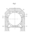
- the Fig. 2 shows, for example, the location of two additional lubricant receiving spaces 15 and 16. These are here above the center plane. Depending on the direction of rotation of the roller, the lubricant drops 17 are thrown against the outer surfaces 18 or 19 of the lubricant collecting channel 22 in a reinforced manner.
- the lubricant 2 can flow into the lubricant receiving chambers 15 or 16.
- the lubricant 2, which exits below the lubricant accommodating spaces 15, 16, is led into the lower lubricant accommodating spaces 20, 21.
- the illustrated embodiment of a chock 1 with four lubricant receiving chambers 15, 16, 20 and 21 and thus four holes is to be seen as an example. Depending on the design of the chock 1 and other lubricant receiving spaces and holes can be considered.
Landscapes
- Engineering & Computer Science (AREA)
- General Engineering & Computer Science (AREA)
- Mechanical Engineering (AREA)
- Chemical & Material Sciences (AREA)
- Oil, Petroleum & Natural Gas (AREA)
- Rolling Contact Bearings (AREA)
- Rolls And Other Rotary Bodies (AREA)
- Seats For Vehicles (AREA)
- Insertion Pins And Rivets (AREA)
- Sliding-Contact Bearings (AREA)
- Support Of The Bearing (AREA)
Description
- Die Erfindung betrifft ein Einbaustück zur Aufnahme des Walzenzapfens einer in der Stahl- und Nichteisenmetallbearbeitung verwendeten Walze gemäss dem Obenbegriff des Anspruch 1. Ein solches Einbaustück ist aus
EP 285 333 A - Ein solches Einbaustück ist aus der
US 4,285,551 bekannt.GB 15 611 US-A-3 433 542 offenbart ein Beispiel für einen Aufnahmeraum. - Walzenzapfenlager, insbesondere Morgoil - Walzenzapfenlager, werden im Walzwerksbau seit Jahrzehnten eingesetzt. Hierbei sind alle lasttragenden Lagerteile einschließlich der Befestigungselemente und Dichtungen in einem Lagergehäuse, dem sogenannten Einbaustück, untergebracht.
- Auf den Zapfen der Walzen, den Walzenzapfen, befinden sich Zapfenbuchsen. Zusammen mit der Lagerbuchse bilden die Zapfenbuchsen ein Radiallager, wobei die Lagerbuchse im Einbaustück festgelegt ist. Die Lagerbuchse umschließt dabei die Zapfenbuchse.
- Zwischen der äußeren Oberfläche der Zapfenbuchse und der inneren Oberfläche der Lagerbuchse befindet sich ein Ölfilm, der den metallischen Kontakt der Lagergleitflächen ausschließt. Das Öl wird kontinuierlich durch das Lager gedrückt. Dieses bedeutet, dass sich das Öl in einem Kreislauf befindet. Der Einlauf des Öls in das Radiallager erfolgt durch Öleinlauftaschen. Diese befinden sich in der Lagerbuchse und werden durch Leitungen, die in den Einbaustücken als Bohrungen ausgeführt sind, mit Öl aus einem Öltank versorgt.
- Durch den konstanten Druck der Ölpumpen gelangt das Öl auf die Lagergleitflächen und verteilt sich dort. Überschüssiges Öl tritt an den beiden Seitenkanten aus, wird dort aufgefangen und über Ablaufleitungen zum Öltank zurückgeführt.
- Damit beim Walzen kein Öl aus den Lagern auf das Walzgut gelangt, befindet sich auf der Ballenseite eine Abdichtung. Die Abdichtung eines Ölfilmlagers kann durch ein formgepreßtes Gummiprofil erfolgen. Die Abdichtung bewirkt, dass das aus dem Lager austretende Öl in Hohlräume des Einbaustückes gelangt, von wo eine Weiterleitung erfolgt.
- Die Weiterleitung des auf der Ballenseite in Auffangkammern gesammelten Öls erfolgt bei bekannten Einbaustücken durch zwei Bohrungen, welche die Ballenseite mit der Ablaufseite verbinden. Die Bohrungen befinden sich unterhalb des tiefsten Lagerpunktes. Das Öl fließt durch die Bohrungen zu einem Ölauffangraum auf der Außenseite des Einbaustückes. Von hier aus wird das Öl über zwei Bohrungsanschlüsse üblicherweise durch bewegliche Schläuche in die Rücklaufleitung zum Öltank geführt.
- Beim Betrieb eines Walzwerkes kann die Funktion der ballenseitigen Abdichtung gestört werden. Beispielsweise läuft die Dichtungslippe der ballenseitgen Abdichtung durch einen Anstieg des Öls in der Auffangkammer in einem Ölsumpf. Eine weitere Störung beruht beispielsweise auf den Verschleiß der Lichtlippen einer Abdichtung. Die Eigenschaften der Dichtungslippe verändern sich in der Weise, dass Öl austreten kann. Dieses führt zu einer Ölleckage und zu großen Ölmengenverlusten. Bei Kaltstraßen erfolgt durch den Ölaustritt z.B. eine Bandbeschmutzung, welche die Qualität des Produktes beeinträchtigt.
- Aus der
EP 0 285 333 B1 ist eine Lagerbuchse bekannt, die durch einen in der Lagermitte befindlichen Ringkanal in zwei Lagerstellen aufgeteilt ist. Über diesen Ringkanal werden ca. 50 % des aus dem Lager abfließenden Öls abgeleitet. Das ballenseitige Dichtungssystem wird nur noch mit der Hälfte der üblichen Ölmenge belastet. Die Möglichkeit, dass Öl unkontrolliert austritt, wird verringert. - Hierbei ist es notwendig, beide Bereiche der Lagerbuchse mit einem eigenen Einlass, durch welchen Öl der Innenlagerfläche zugeführt wird, auszustatten. Weiterhin sind in dem Ringkanal Auslassöffnungen zur Abführung des Öls eingebracht. Diese zusätzlichen Maßnahmen bewirken einen erhöhten Herstellungsaufwand.
- Der Erfindung liegt daher die Aufgabe zugrunde, ein Einbaustück der eingangs beschriebenen Art alternativ auszubilden.
- Diese Aufgabe wird erfindungsgemäß durch den Gegenstand des Anspruchs 1 gelöst. Indem das Schmiermittel in zusätzlichen Schmiermittelaufnahmeräumen in dem Einbaustück aufgefangen wird, kann der Kontakt der Dichtungslippe der ballenseitigen Abdichtung mit dem Schmiermittel reduziert und das Einbaustück wirtschaftlich hergestellt werden.
- Als Ausgestaltung wird vorgeschlagen, dass auf der Ballenseite mindestens vier Schmiermittelaufnahmeräume vorhanden sind.
- In Weiterbildung dieser Bauweise wird vorgeschlagen, dass die zusätzlichen ballenseitigen Schmiermittelaufnahmeräume durch separate Bohrungen mit Schmiermittelaufnahmeräumen auf der Ablaufseite verbunden sind.
- Als eine Weiterentwicklung ist vorgesehen, dass die rückfließenden Schmiermittelströme auf der Ablaufseite zusammengeführt werden. Von dort werden sie gemeinsam in Vorratstanks geleitet, wo das Öl gereinigt und / oder gekühlt wird.
- Das in den Aufnahmeräumen gelangte Schmiermittel wird durch Bohrungen auf die Ablaufseite geleitet. Hierdurch wird erreicht, dass sich die Schmiermittelmenge in den bisher bekannten unteren Aufnahmeräumen verringert. Die Höhe des Schmiermittelstandes wird im unteren Bereich gesenkt und die Dichtlippen des ballenseitigen Dichtungssystems z.B. laufen nicht mehr in einem Schmiermittelsumpf.
- Die Erfindung wird anhand von sehr schematischen Zeichnungen näher beschrieben. Es zeigen:
- Fig. 1
- einen Halbschnitt eines Einbaustückes und
- Fig. 2
- eine Frontalansicht des Einbaustückes aus
Fig. 1 entlang der Schnittebene X - X - In dem Einbaustück 1 wird ein Walzenzapfen (nicht dargestellt) durch eine Zapfenbuchs (nicht dargestellt) und eine Lagerbuchse (nicht dargestellt) gelagert. Während die Zapfenbuchse drehfest mit dem Walzenzapfen verbunden ist, wird die Lagerbuchse im Einbaustück 1 festgelegt. Zwischen Lagerbuchse und Zapfenbuchse befindet sich ein kontinuierlicher Schmiermittelfilm. Das Schmiermittel 2 gelangt durch ein Schmiermittelumlaufsystem über Schmiermitteleinlauftaschen in den Spalt zwischen Lagerbuchse und Zapfenbuchse. Bei einer symmetrischen Lastverteilung wird das Schmiermittel 2 je zur Hälfte auf der Ballenseite 3 und der Abflaufseite 4 ablaufen. Zur Ableitung des Schmiermittels 2 sind in dem Einbaustück 1 auf der Ballenseite 3 und der Ablaufseite 4 umlaufende Schmiermittelauffangrinnen 5, 6 eingearbeitet. Diese Schmiermittelauffangrinnen 5, 6 werden im unteren Bereich erweitert zu zwei Schmiermittelaufnahmeräumen 7, 8 , die sich unterhalb des tiefsten Punktes 9 der Lagerbuchse befinden.
- Die bekannte, unten im Einbaustück 1 angeordnete Bohrung 10 bewirkt ein Ableiten des Schmiermittels 2 aus dem Schmiermittelaufnahmeraum 7 auf der Ballenseite 3 zur Ablaufseite 4 des Einbaustückes 1. Das Schmiermittel 2 wird auf der Ablaufseite 4 in einem Schmiermittelaufnahmeraum 8 aufgefangen und von dort über einen beweglichen Schlauch 11 zu einem nicht dargestellten Schmiermitteltank geführt.
Dort kann das Schmiermittel 2 gereinigt und / oder gekühlt werden, um anschließend wieder in das Lager gefördert zu werden.
Zur besseren Ableitung des Schmiermittels 2 befindet sich oberhalb der Mittelebene ein weiterer Schmiermittelaufnahmeraum 12. Dieser Schmiermittelaufnahmeraum 12 ist durch eine Bohrung 13 mit der Ablaufseite 4 verbunden. Das Schmiermittel 2 wird auf der Ablaufseite 4 durch ein Verbindungsstück 14 in den Schlauch 11 geleitet. - Die
Fig. 2 zeigt beispielsweise die Lage von zwei zusätzlichen Schmiermittelaufnahmeräumen 15 und 16. Diese befinden sich hier oberhalb der Mittelebene. Je nach Drehrichtung der Walze werden die Schmiermitteltropfen 17 verstärkt an die Außenflächen 18 oder 19 der Schmiermittelauffangrinne 22 geschleudert. - Von dort kann das Schmiermittel 2 in die Schmiermittelaufnahmeräume 15 oder 16 abfließen. Das Schmiermittel 2, welches unterhalb der Schmiermittelaufnahmeräume 15, 16 austritt, wird in die unteren Schmiermittelaufnahmeräume 20, 21 geleitet.
- Die gezeigte Ausführung eines Einbaustückes 1 mit vier Schmiermittelaufnahmeräumen 15, 16, 20 und 21 und somit auch vier Bohrungen ist als Beispiel zu sehen. Je nach Ausführung des Einbaustückes 1 können auch weitere Schmiermittelaufnahmeräume und Bohrungen berücksichtigt werden.
-
- 1
- Einbaustück
- 2
- Schmiermittel
- 3
- Ballenseite
- 4
- Ablaufseite
- 5
- Schmiermittelauffangrinne
- 6
- Schmiermittelauffangrinne
- 7
- unterer Schmiermittelaufnahmeraum
- 8
- unterer Schmiermittelaufnahmeraum
- 9
- tiefster Punkt der Lagerbuchse
- 10
- Bohrung
- 11
- Schlauch
- 12
- Schmiermittelaufnahmeraum
- 13
- Bohrung
- 14
- Verbindungsstück
- 15
- oberer Schmiermittelaufnahmeraum
- 16
- oberer Schmiermittelaufnahmeraum
- 17
- Schmiermitteltropfen
- 18
- Außenfläche
- 19
- Außenfläche
- 20
- Schmiermittelaufnahmeraum
- 21
- Schmiermittelaufnahmeraum
- 22
- Schmiermittelauffangrinne
Claims (3)
- Einbaustück zur Aufnahme des Walzenzapfens einer in der Stahl- und Nichteisenmetallbearbeitung verwendeten Walze, mit mindestens einem Schmiermittelaufnahmeraum auf der Ballenseite und mit mindestens einem Schmiermittelaufnahmeraum auf der Abflussseite, welche unterhalb des tiefsten Lagerpunktes angeordnet sind, sowie Verbindungsbohrungen zwischen den Schmiermittelaufnahmeräumen auf der Ballen- und der Ablaufseite,
dadurch gekennzeichnet,
dass das Schmiermittel (2) in zusätzlichen oberhalb oder in Höhe der Mittelebene angeordneten Schmiermittelaufnahmeräumen (12, 15, 16) aufgefangen wird; und
dass die zusätzlichen ballenseitigen Schmiermittelaufnahmeräume (15, 16) durch separate Bohrungen (13) mit Schmiermittelaufnahmeräumen auf der Ablaufseite (4) verbunden sind. - Einbaustück nach Anspruch 1,
dadurch gekennzeichnet,
dass auf der Ballenseite (3) mindestens vier Schmiermittelaufnahmeräume (15, 16, 20, 21) vorhanden sind. - Einbaustück nach Anspruch 2,
dadurch gekennzeichnet,
dass die rückfließenden Schmiermittelströme auf der Ablaufseite (4) zusammengeführt werden.
Applications Claiming Priority (3)
| Application Number | Priority Date | Filing Date | Title |
|---|---|---|---|
| DE10302271 | 2003-01-22 | ||
| DE10302271.6A DE10302271B4 (de) | 2003-01-22 | 2003-01-22 | Einbaustück zur Aufnahme eines Walzenzapfens |
| PCT/EP2004/000279 WO2004065031A1 (de) | 2003-01-22 | 2004-01-16 | Einbaustück zur aufnahme eines walzenzapfens |
Publications (2)
| Publication Number | Publication Date |
|---|---|
| EP1585606A1 EP1585606A1 (de) | 2005-10-19 |
| EP1585606B1 true EP1585606B1 (de) | 2015-04-08 |
Family
ID=32602845
Family Applications (1)
| Application Number | Title | Priority Date | Filing Date |
|---|---|---|---|
| EP04702676.0A Expired - Lifetime EP1585606B1 (de) | 2003-01-22 | 2004-01-16 | Einbaustück zur aufnahme eines walzenzapfens |
Country Status (9)
| Country | Link |
|---|---|
| US (1) | US7789568B2 (de) |
| EP (1) | EP1585606B1 (de) |
| JP (1) | JP2006515805A (de) |
| KR (1) | KR20050094455A (de) |
| CN (1) | CN100344389C (de) |
| BR (1) | BRPI0406868A (de) |
| DE (1) | DE10302271B4 (de) |
| RU (1) | RU2339470C2 (de) |
| WO (1) | WO2004065031A1 (de) |
Families Citing this family (11)
| Publication number | Priority date | Publication date | Assignee | Title |
|---|---|---|---|---|
| US6802511B1 (en) * | 2003-02-12 | 2004-10-12 | Morgan Construction Company | Seal end plate |
| US20050281499A1 (en) * | 2004-06-22 | 2005-12-22 | Wojtkowski Thomas Jr | Oil outlet for rolling mill oil film bearing |
| DE102006016714A1 (de) | 2006-04-08 | 2007-10-11 | Sms Demag Ag | Einbaustück zur Aufnahme eines Walzenzapfens |
| CN100464884C (zh) * | 2006-12-07 | 2009-03-04 | 郑红专 | 自润滑分段轧辊座 |
| SA08290562B1 (ar) * | 2007-09-12 | 2011-08-10 | ريبس زينتر الشميرتيكنيك جي ام بي اتش | حامل مدلفنة لدلفنة شرائط فلزية ومدلفنة أو أسطوانة لحامل مدلفنة من هذا النوع |
| US8500332B2 (en) * | 2010-05-05 | 2013-08-06 | Siemens Industry, Inc. | Self pumping oil film bearing |
| DE102011087605A1 (de) * | 2011-12-01 | 2013-06-06 | Sms Siemag Ag | Einbaustück und Verfahren zu dessen Herstellung |
| DE102012224511A1 (de) * | 2012-12-28 | 2014-07-03 | Sms Siemag Ag | Einbaustück zum Lagern einer Walze in einem Walzenständer |
| JP6250637B2 (ja) * | 2013-03-27 | 2017-12-20 | 日本ゼオン株式会社 | 静電荷像現像用トナー |
| US20150234974A1 (en) * | 2014-02-17 | 2015-08-20 | Samsung Electronics Co., Ltd. | Multiple patterning design with reduced complexity |
| CN114233752A (zh) * | 2021-12-07 | 2022-03-25 | 昆山旭义富机械设备有限公司 | 一种便于取出的传电轮用可拆式铜套 |
Family Cites Families (13)
| Publication number | Priority date | Publication date | Assignee | Title |
|---|---|---|---|---|
| GB191415611A (en) * | 1914-06-30 | 1915-02-18 | David Jones | Improvements in or connected with the Lubrication of Rolls used in Sheet Metal Rolling Mills and the like. |
| US1900593A (en) * | 1929-09-16 | 1933-03-07 | Gen Electric | Shaft bearing |
| US3433542A (en) * | 1964-06-08 | 1969-03-18 | Hitachi Ltd | Multiface cylindrical bearings for guiding rotation of vertical shafts |
| US3453031A (en) * | 1967-04-06 | 1969-07-01 | Morgan Construction Co | Bearing assembly |
| FR2081969A5 (de) * | 1969-10-10 | 1971-12-10 | Gerard Paul | |
| US3734580A (en) * | 1971-06-22 | 1973-05-22 | Gen Electric | Split sleeve bearing with integral seals |
| SU710695A1 (ru) * | 1976-03-04 | 1980-01-25 | Предприятие П/Я В-2869 | Подшипник жидкостного трени |
| CA1096431A (en) * | 1978-07-03 | 1981-02-24 | Kunio Shibata | Fluid bearing |
| SU995935A1 (ru) * | 1980-12-17 | 1983-02-15 | За витель ог-,.. -с«з-а р - - ... . н if МЛ 5i# SJitjQ-i-ft. | Опора рабочего валка |
| US4749283A (en) * | 1985-09-12 | 1988-06-07 | Canon Kabushiki Kaisha | Static pressure bearing |
| US4772137A (en) * | 1987-03-30 | 1988-09-20 | Morgan Construction Company | Oil film bearing and bushing |
| RU2176939C2 (ru) * | 1998-02-18 | 2001-12-20 | Открытое акционерное общество "Электростальский завод тяжелого машиностроения" | Гидростатодинамический подшипник жидкостного трения для валков прокатных станов |
| US6278334B1 (en) | 1999-11-29 | 2001-08-21 | Arm Limited | Voltage controlled oscillator with accelerating and decelerating circuits |
-
2003
- 2003-01-22 DE DE10302271.6A patent/DE10302271B4/de not_active Expired - Lifetime
-
2004
- 2004-01-16 CN CNB2004800025520A patent/CN100344389C/zh not_active Expired - Fee Related
- 2004-01-16 BR BR0406868-8A patent/BRPI0406868A/pt active Search and Examination
- 2004-01-16 RU RU2005126415/02A patent/RU2339470C2/ru not_active IP Right Cessation
- 2004-01-16 JP JP2006500576A patent/JP2006515805A/ja active Pending
- 2004-01-16 US US10/543,249 patent/US7789568B2/en not_active Expired - Fee Related
- 2004-01-16 KR KR1020057013429A patent/KR20050094455A/ko not_active Ceased
- 2004-01-16 WO PCT/EP2004/000279 patent/WO2004065031A1/de not_active Ceased
- 2004-01-16 EP EP04702676.0A patent/EP1585606B1/de not_active Expired - Lifetime
Also Published As
| Publication number | Publication date |
|---|---|
| KR20050094455A (ko) | 2005-09-27 |
| RU2339470C2 (ru) | 2008-11-27 |
| WO2004065031A1 (de) | 2004-08-05 |
| CN1802224A (zh) | 2006-07-12 |
| US20070003174A1 (en) | 2007-01-04 |
| US7789568B2 (en) | 2010-09-07 |
| CN100344389C (zh) | 2007-10-24 |
| RU2005126415A (ru) | 2006-02-10 |
| DE10302271B4 (de) | 2014-06-18 |
| DE10302271A1 (de) | 2004-07-29 |
| EP1585606A1 (de) | 2005-10-19 |
| JP2006515805A (ja) | 2006-06-08 |
| BRPI0406868A (pt) | 2006-01-03 |
Similar Documents
| Publication | Publication Date | Title |
|---|---|---|
| EP2005016B1 (de) | Einbaustück zur aufnahme eines walzenzapfens | |
| DE3876663T2 (de) | Oelfilmlager und buchse. | |
| DE19621020C2 (de) | Drehdurchführung für hohe Drücke und hohe Relativgeschwindigkeiten | |
| DE3143206C2 (de) | ||
| DE10302271B4 (de) | Einbaustück zur Aufnahme eines Walzenzapfens | |
| DE29704386U1 (de) | Vierreihiges Kegelrollenlager, insbesondere für Arbeitswalzen von Walzgerüsten | |
| DE60300051T2 (de) | Wellendichtung | |
| EP1514047B1 (de) | Drehdurchführung | |
| DE2350723A1 (de) | Walzenzapfendichtung | |
| DE19541615C1 (de) | Drehdurchführung für die Kühlwasserzu- und ableitung einer Führungsrolle in einer Stranggießanlage | |
| EP3302836B1 (de) | Walzenanordnung | |
| EP3380257B1 (de) | Volumenstrom-regelventil | |
| EP2188073B1 (de) | Walzgerüst zum walzen von metallischen bändern sowie walze oder rolle für ein solches walzgerüst | |
| DE2806418A1 (de) | Lagerbuechse zur aufnahme eines walzenzapfens | |
| DE102009019418B4 (de) | Umlaufverdrängerpumpe mit verbesserter Lagerschmierung | |
| DE102015219752A1 (de) | Lagerbuchse | |
| DE10059196C2 (de) | Axialgleitlager für rotierende Wellen | |
| EP1539388B1 (de) | Dichtungsvorrichtung mit eineim zweiteiligen ringkörper | |
| DE620581C (de) | Gleitlager fuer den abgesetzten Zapfen einer Walzwerkswalze | |
| DE102006012001A1 (de) | Hochgeschwindigkeitslager, insbesondere direktgeschmiertes Spindellager für eine Werkzeugmaschine | |
| DE3013135C2 (de) | Lagerausbildung für die Kurbelwelle eines Kaltpilgerwalzwerkes | |
| EP2842716A1 (de) | Schneckenmaschine und Verfahren zur Aufbereitung von Kunststoffschmelzen | |
| DE2034399A1 (de) | Hydrodynamisches Drucklager fur Pumpen oder Motoren mit Axialkolben | |
| EP1256730B1 (de) | Biegeeinstellwalzewälzlager | |
| DE102007043403B3 (de) | Walzgerüst zum Walzen von metallischen Bändern sowie Walze oder Rolle für ein solches Walzgerüst |
Legal Events
| Date | Code | Title | Description |
|---|---|---|---|
| PUAI | Public reference made under article 153(3) epc to a published international application that has entered the european phase |
Free format text: ORIGINAL CODE: 0009012 |
|
| 17P | Request for examination filed |
Effective date: 20050617 |
|
| AK | Designated contracting states |
Kind code of ref document: A1 Designated state(s): AT BE BG CH CY CZ DE DK EE ES FI FR GB GR HU IE IT LI LU MC NL PT RO SE SI SK TR |
|
| AX | Request for extension of the european patent |
Extension state: AL LT LV MK |
|
| DAX | Request for extension of the european patent (deleted) | ||
| RAP1 | Party data changed (applicant data changed or rights of an application transferred) |
Owner name: SMS SIEMAG AG |
|
| 17Q | First examination report despatched |
Effective date: 20110215 |
|
| GRAP | Despatch of communication of intention to grant a patent |
Free format text: ORIGINAL CODE: EPIDOSNIGR1 |
|
| INTG | Intention to grant announced |
Effective date: 20141121 |
|
| GRAS | Grant fee paid |
Free format text: ORIGINAL CODE: EPIDOSNIGR3 |
|
| GRAA | (expected) grant |
Free format text: ORIGINAL CODE: 0009210 |
|
| AK | Designated contracting states |
Kind code of ref document: B1 Designated state(s): AT BE BG CH CY CZ DE DK EE ES FI FR GB GR HU IE IT LI LU MC NL PT RO SE SI SK TR |
|
| REG | Reference to a national code |
Ref country code: GB Ref legal event code: FG4D Free format text: NOT ENGLISH |
|
| REG | Reference to a national code |
Ref country code: DE Ref legal event code: R081 Ref document number: 502004014879 Country of ref document: DE Owner name: SMS GROUP GMBH, DE Free format text: FORMER OWNER: SMS DEMAG AG, 40237 DUESSELDORF, DE |
|
| REG | Reference to a national code |
Ref country code: CH Ref legal event code: EP |
|
| REG | Reference to a national code |
Ref country code: IE Ref legal event code: FG4D Free format text: LANGUAGE OF EP DOCUMENT: GERMAN |
|
| REG | Reference to a national code |
Ref country code: AT Ref legal event code: REF Ref document number: 720124 Country of ref document: AT Kind code of ref document: T Effective date: 20150515 |
|
| REG | Reference to a national code |
Ref country code: DE Ref legal event code: R096 Ref document number: 502004014879 Country of ref document: DE Effective date: 20150521 |
|
| RAP2 | Party data changed (patent owner data changed or rights of a patent transferred) |
Owner name: SMS GROUP GMBH |
|
| REG | Reference to a national code |
Ref country code: DE Ref legal event code: R082 Ref document number: 502004014879 Country of ref document: DE Representative=s name: HEMMERICH & KOLLEGEN, DE Ref country code: DE Ref legal event code: R081 Ref document number: 502004014879 Country of ref document: DE Owner name: SMS GROUP GMBH, DE Free format text: FORMER OWNER: SMS SIEMAG AG, 40237 DUESSELDORF, DE |
|
| REG | Reference to a national code |
Ref country code: NL Ref legal event code: VDEP Effective date: 20150408 |
|
| PG25 | Lapsed in a contracting state [announced via postgrant information from national office to epo] |
Ref country code: NL Free format text: LAPSE BECAUSE OF FAILURE TO SUBMIT A TRANSLATION OF THE DESCRIPTION OR TO PAY THE FEE WITHIN THE PRESCRIBED TIME-LIMIT Effective date: 20150408 |
|
| PG25 | Lapsed in a contracting state [announced via postgrant information from national office to epo] |
Ref country code: PT Free format text: LAPSE BECAUSE OF FAILURE TO SUBMIT A TRANSLATION OF THE DESCRIPTION OR TO PAY THE FEE WITHIN THE PRESCRIBED TIME-LIMIT Effective date: 20150810 Ref country code: FI Free format text: LAPSE BECAUSE OF FAILURE TO SUBMIT A TRANSLATION OF THE DESCRIPTION OR TO PAY THE FEE WITHIN THE PRESCRIBED TIME-LIMIT Effective date: 20150408 Ref country code: ES Free format text: LAPSE BECAUSE OF FAILURE TO SUBMIT A TRANSLATION OF THE DESCRIPTION OR TO PAY THE FEE WITHIN THE PRESCRIBED TIME-LIMIT Effective date: 20150408 |
|
| PG25 | Lapsed in a contracting state [announced via postgrant information from national office to epo] |
Ref country code: GR Free format text: LAPSE BECAUSE OF FAILURE TO SUBMIT A TRANSLATION OF THE DESCRIPTION OR TO PAY THE FEE WITHIN THE PRESCRIBED TIME-LIMIT Effective date: 20150709 |
|
| REG | Reference to a national code |
Ref country code: DE Ref legal event code: R097 Ref document number: 502004014879 Country of ref document: DE |
|
| PG25 | Lapsed in a contracting state [announced via postgrant information from national office to epo] |
Ref country code: DK Free format text: LAPSE BECAUSE OF FAILURE TO SUBMIT A TRANSLATION OF THE DESCRIPTION OR TO PAY THE FEE WITHIN THE PRESCRIBED TIME-LIMIT Effective date: 20150408 Ref country code: EE Free format text: LAPSE BECAUSE OF FAILURE TO SUBMIT A TRANSLATION OF THE DESCRIPTION OR TO PAY THE FEE WITHIN THE PRESCRIBED TIME-LIMIT Effective date: 20150408 |
|
| PLBE | No opposition filed within time limit |
Free format text: ORIGINAL CODE: 0009261 |
|
| STAA | Information on the status of an ep patent application or granted ep patent |
Free format text: STATUS: NO OPPOSITION FILED WITHIN TIME LIMIT |
|
| PG25 | Lapsed in a contracting state [announced via postgrant information from national office to epo] |
Ref country code: CZ Free format text: LAPSE BECAUSE OF FAILURE TO SUBMIT A TRANSLATION OF THE DESCRIPTION OR TO PAY THE FEE WITHIN THE PRESCRIBED TIME-LIMIT Effective date: 20150408 Ref country code: RO Free format text: LAPSE BECAUSE OF NON-PAYMENT OF DUE FEES Effective date: 20150408 Ref country code: SK Free format text: LAPSE BECAUSE OF FAILURE TO SUBMIT A TRANSLATION OF THE DESCRIPTION OR TO PAY THE FEE WITHIN THE PRESCRIBED TIME-LIMIT Effective date: 20150408 |
|
| 26N | No opposition filed |
Effective date: 20160111 |
|
| PG25 | Lapsed in a contracting state [announced via postgrant information from national office to epo] |
Ref country code: BE Free format text: LAPSE BECAUSE OF NON-PAYMENT OF DUE FEES Effective date: 20160131 Ref country code: SI Free format text: LAPSE BECAUSE OF FAILURE TO SUBMIT A TRANSLATION OF THE DESCRIPTION OR TO PAY THE FEE WITHIN THE PRESCRIBED TIME-LIMIT Effective date: 20150408 |
|
| PG25 | Lapsed in a contracting state [announced via postgrant information from national office to epo] |
Ref country code: LU Free format text: LAPSE BECAUSE OF FAILURE TO SUBMIT A TRANSLATION OF THE DESCRIPTION OR TO PAY THE FEE WITHIN THE PRESCRIBED TIME-LIMIT Effective date: 20160116 |
|
| REG | Reference to a national code |
Ref country code: CH Ref legal event code: PL |
|
| GBPC | Gb: european patent ceased through non-payment of renewal fee |
Effective date: 20160116 |
|
| PG25 | Lapsed in a contracting state [announced via postgrant information from national office to epo] |
Ref country code: MC Free format text: LAPSE BECAUSE OF FAILURE TO SUBMIT A TRANSLATION OF THE DESCRIPTION OR TO PAY THE FEE WITHIN THE PRESCRIBED TIME-LIMIT Effective date: 20150408 |
|
| REG | Reference to a national code |
Ref country code: FR Ref legal event code: ST Effective date: 20160930 |
|
| PG25 | Lapsed in a contracting state [announced via postgrant information from national office to epo] |
Ref country code: GB Free format text: LAPSE BECAUSE OF NON-PAYMENT OF DUE FEES Effective date: 20160116 Ref country code: CH Free format text: LAPSE BECAUSE OF NON-PAYMENT OF DUE FEES Effective date: 20160131 Ref country code: LI Free format text: LAPSE BECAUSE OF NON-PAYMENT OF DUE FEES Effective date: 20160131 |
|
| REG | Reference to a national code |
Ref country code: IE Ref legal event code: MM4A |
|
| PG25 | Lapsed in a contracting state [announced via postgrant information from national office to epo] |
Ref country code: FR Free format text: LAPSE BECAUSE OF NON-PAYMENT OF DUE FEES Effective date: 20160201 |
|
| PG25 | Lapsed in a contracting state [announced via postgrant information from national office to epo] |
Ref country code: IE Free format text: LAPSE BECAUSE OF NON-PAYMENT OF DUE FEES Effective date: 20160116 |
|
| PGFP | Annual fee paid to national office [announced via postgrant information from national office to epo] |
Ref country code: DE Payment date: 20170120 Year of fee payment: 14 |
|
| PGFP | Annual fee paid to national office [announced via postgrant information from national office to epo] |
Ref country code: AT Payment date: 20170123 Year of fee payment: 14 |
|
| PG25 | Lapsed in a contracting state [announced via postgrant information from national office to epo] |
Ref country code: SE Free format text: LAPSE BECAUSE OF FAILURE TO SUBMIT A TRANSLATION OF THE DESCRIPTION OR TO PAY THE FEE WITHIN THE PRESCRIBED TIME-LIMIT Effective date: 20150408 |
|
| PGFP | Annual fee paid to national office [announced via postgrant information from national office to epo] |
Ref country code: IT Payment date: 20170124 Year of fee payment: 14 |
|
| PG25 | Lapsed in a contracting state [announced via postgrant information from national office to epo] |
Ref country code: HU Free format text: LAPSE BECAUSE OF FAILURE TO SUBMIT A TRANSLATION OF THE DESCRIPTION OR TO PAY THE FEE WITHIN THE PRESCRIBED TIME-LIMIT; INVALID AB INITIO Effective date: 20040116 Ref country code: CY Free format text: LAPSE BECAUSE OF FAILURE TO SUBMIT A TRANSLATION OF THE DESCRIPTION OR TO PAY THE FEE WITHIN THE PRESCRIBED TIME-LIMIT Effective date: 20150408 |
|
| PG25 | Lapsed in a contracting state [announced via postgrant information from national office to epo] |
Ref country code: TR Free format text: LAPSE BECAUSE OF FAILURE TO SUBMIT A TRANSLATION OF THE DESCRIPTION OR TO PAY THE FEE WITHIN THE PRESCRIBED TIME-LIMIT Effective date: 20150408 |
|
| PG25 | Lapsed in a contracting state [announced via postgrant information from national office to epo] |
Ref country code: BG Free format text: LAPSE BECAUSE OF FAILURE TO SUBMIT A TRANSLATION OF THE DESCRIPTION OR TO PAY THE FEE WITHIN THE PRESCRIBED TIME-LIMIT Effective date: 20150408 |
|
| REG | Reference to a national code |
Ref country code: DE Ref legal event code: R119 Ref document number: 502004014879 Country of ref document: DE |
|
| REG | Reference to a national code |
Ref country code: AT Ref legal event code: MM01 Ref document number: 720124 Country of ref document: AT Kind code of ref document: T Effective date: 20180116 |
|
| PG25 | Lapsed in a contracting state [announced via postgrant information from national office to epo] |
Ref country code: DE Free format text: LAPSE BECAUSE OF NON-PAYMENT OF DUE FEES Effective date: 20180801 |
|
| PG25 | Lapsed in a contracting state [announced via postgrant information from national office to epo] |
Ref country code: AT Free format text: LAPSE BECAUSE OF NON-PAYMENT OF DUE FEES Effective date: 20180116 |
|
| PG25 | Lapsed in a contracting state [announced via postgrant information from national office to epo] |
Ref country code: IT Free format text: LAPSE BECAUSE OF NON-PAYMENT OF DUE FEES Effective date: 20180116 |