EP1584694A1 - Durchhangofen - Google Patents
Durchhangofen Download PDFInfo
- Publication number
- EP1584694A1 EP1584694A1 EP03776019A EP03776019A EP1584694A1 EP 1584694 A1 EP1584694 A1 EP 1584694A1 EP 03776019 A EP03776019 A EP 03776019A EP 03776019 A EP03776019 A EP 03776019A EP 1584694 A1 EP1584694 A1 EP 1584694A1
- Authority
- EP
- European Patent Office
- Prior art keywords
- furnace
- burners
- burner
- catenary
- casing
- Prior art date
- Legal status (The legal status is an assumption and is not a legal conclusion. Google has not performed a legal analysis and makes no representation as to the accuracy of the status listed.)
- Granted
Links
- 230000001172 regenerating effect Effects 0.000 claims abstract description 72
- 239000000463 material Substances 0.000 claims abstract description 58
- 238000002485 combustion reaction Methods 0.000 claims abstract description 26
- 238000010438 heat treatment Methods 0.000 claims abstract description 18
- 238000011144 upstream manufacturing Methods 0.000 claims description 10
- 238000009792 diffusion process Methods 0.000 claims description 3
- 230000007613 environmental effect Effects 0.000 abstract description 6
- 230000000452 restraining effect Effects 0.000 abstract description 4
- 238000012423 maintenance Methods 0.000 description 5
- 230000003247 decreasing effect Effects 0.000 description 4
- 0 C1CC*CC1 Chemical compound C1CC*CC1 0.000 description 2
- 238000000137 annealing Methods 0.000 description 2
- 238000010586 diagram Methods 0.000 description 2
- 230000000694 effects Effects 0.000 description 2
- 238000000034 method Methods 0.000 description 2
- 230000005855 radiation Effects 0.000 description 2
- RVZFGUVMWKYTBH-GGWGRWFQSA-N CC[C@@H]([C@@](C)(C(C)CC(C)C1(C2(C)CC)C(C=O)=C)C12NC)N=O Chemical compound CC[C@@H]([C@@](C)(C(C)CC(C)C1(C2(C)CC)C(C=O)=C)C12NC)N=O RVZFGUVMWKYTBH-GGWGRWFQSA-N 0.000 description 1
- 230000002411 adverse Effects 0.000 description 1
- 238000010276 construction Methods 0.000 description 1
- 239000000446 fuel Substances 0.000 description 1
- 238000009434 installation Methods 0.000 description 1
- 238000012986 modification Methods 0.000 description 1
- 230000004048 modification Effects 0.000 description 1
- 239000011819 refractory material Substances 0.000 description 1
- 238000007665 sagging Methods 0.000 description 1
Images


Classifications
-
- C—CHEMISTRY; METALLURGY
- C21—METALLURGY OF IRON
- C21D—MODIFYING THE PHYSICAL STRUCTURE OF FERROUS METALS; GENERAL DEVICES FOR HEAT TREATMENT OF FERROUS OR NON-FERROUS METALS OR ALLOYS; MAKING METAL MALLEABLE, e.g. BY DECARBURISATION OR TEMPERING
- C21D1/00—General methods or devices for heat treatment, e.g. annealing, hardening, quenching or tempering
- C21D1/34—Methods of heating
- C21D1/52—Methods of heating with flames
-
- C—CHEMISTRY; METALLURGY
- C21—METALLURGY OF IRON
- C21D—MODIFYING THE PHYSICAL STRUCTURE OF FERROUS METALS; GENERAL DEVICES FOR HEAT TREATMENT OF FERROUS OR NON-FERROUS METALS OR ALLOYS; MAKING METAL MALLEABLE, e.g. BY DECARBURISATION OR TEMPERING
- C21D9/00—Heat treatment, e.g. annealing, hardening, quenching or tempering, adapted for particular articles; Furnaces therefor
- C21D9/52—Heat treatment, e.g. annealing, hardening, quenching or tempering, adapted for particular articles; Furnaces therefor for wires; for strips ; for rods of unlimited length
- C21D9/54—Furnaces for treating strips or wire
- C21D9/56—Continuous furnaces for strip or wire
Definitions
- the present invention relates to a catenary furnace which has high compatibility with environmental protection, is easy to maintain, and can satisfactorily perform heating treatment of a material to be treated by restraining fluctuations in furnace temperature.
- a catenary furnace which is a kind of horizontal furnaces, performs heating treatment such as annealing to a material to be treated in a furnace casing heated by burners.
- the furnace casing of the catenary furnace is formed long in the longitudinal dimension corresponding to the direction in which the material is conveyed and short in the transverse dimension defined by a pair of furnace side walls so as to match the width of the material.
- the material is pulled by a horizontal tension, and is conveyed in the longitudinal direction of the furnace casing.
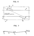
- the material (a) deflects due to its own weight against the tension for conveying the material (a), and sags down between support rolls (b) for supporting the material (a) thereon, whichprovides a catenary curve forming a catenary sag (c) with a considerable sagging amount (h) .
- an ordinary burner of a general type is used as a burner for heating the material having a shape of such a catenary curve.
- a large number of the burner are arranged at the upper side and lower side of the material and toward the furnace width direction from one furnace side wall to the other furnace side wall, whereby the material is heated from the upper side and lower side by heat radiations of the furnace wall heated by the burners and the burner flames.
- the width of furnace casing is narrow so as to match the width of the material. Therefore, if the capacity of burner is increased to obtain a larger heat input, the burner flames become longer than the transverse dimension of the furnace casing, and hence collide with the other furnace side wall facing thereto. Therefore, the other furnace side wall is overheated, and thereby refractories are damaged.
- burners with a low capacity have conventionally been arranged in a plural for the purpose of securing a necessary heat input.
- the conventional ordinary burner has a problem in terms of measures against exhaust gas, and also has low energy-saving performance. Therefore, a usage of a large number of such burners lacks compatibility with environmental protection, and it has been desired to constitute a furnace casing structure provided with burners replacing the above-described ordinary burners.
- the regenerative burner is constructed with a pair of burners that are arranged oppositely to alternately perform combustion operation and exhaust operation, a heat reservoir provided in each of the burners, and a selector valve for switching over the burner operation.
- the heat reservoir accumulates heat from exhaust gas during the exhaust operation of burner, and the heat reservoir accumulating heat heats combustion air, when the operation is switched over to the combustion operation. Therefore, the regenerative burner has excellent compatibility with environment.
- the furnace casing structure may be constructed by means that this regenerative burner in place of the above-described ordinaryburner is providedon the furnace side wall and is located at the upper side and lower side of the material.
- the heat input required to the regenerative burner is determined by the quantity of heat necessary for heating the material, the heat loss of exhaust gas, the preheating temperature of combustion air, the heat loss from furnace wall, and the like, and the necessary heat input per one burner of the regenerative burner is approximately two times, as comparing such input with the above-described ordinary burner. I f an attempt is made to secure the heat input two times, the flame length of burner naturally becomes long. Consequently, as in the case of the conventional ordinary burner, a problem of overheated furnace side wall occurs.
- the each heat input thereof must be restricted so as to match the width dimension of furnace casing.
- a considerably large number of regenerative burners must be provided.
- the number of auxiliary device such as the selector valve and heat reservoir increases. Therefore, not only the equipment but also the maintenance works increases.
- the furnace temperature fluctuates greatly, so that the heating treatment of the material may be affected adversely.
- the present invention has been made to solve above problems with the related art, and accordingly an object thereof is to provide a catenary furnace which has high compatibility with environmental protection, is easy to maintain, and can satisfactorily perform heating treatment of a material to be treated by restraining fluctuations in furnace temperature.
- the present invention provides a catenary furnace for heating a material, which is formed in a shape of a catenary curve and is conveyed in the longitudinal direction of a furnace casing, in the furnace casing heated by burners, characterized in that a lower burner, which is burned continuously toward the transverse direction of the furnace casing, is provided on the lower side of the material, and an alternate combustion type regenerative burner, which has a pair of burners burned alternately and is burned toward the longitudinal direction of the furnace casing, is provided on the upper side of the material.
- the regenerative burner can be burned with a necessary heat input without being restricted in the transverse dimension of furnace casing as compared with the case where the regenerative burner is arranged in the furnace width direction, by which the number of regenerative burners can be decreased as the whole of the furnace casing structure.
- the regenerative burner is used as a burner located at the upper side of the material, and on the other hand, the lower burner fired continuously is provided on the lower side of the material.
- the furnace temperature can be kept substantially constant, whereby fluctuations in furnace temperature caused by the switchover control of regenerative burner can be restrained, and the temperature distribution of the material can be maintained satisfactorily, by which proper heating treatment can be performed.
- the number of regenerative burners can be decreased, the maintenance work for auxiliary devices such as a selector valve and a heat reservoir can be lightened. Further, the use of the regenerative burner, which is excellent in terms of measures against exhaust gas and energy saving, can enhance the compatibility with environment of the catenary furnace.
- the catenary furnace in accordance with the present invention is characterized in that one set of the regenerative burner consisting of two is provided, so as to hold the furnace casing between the paired burners each of the regenerative burner from the width direction of the furnace casing.
- the furnace temperature can also be controlled in the furnace width direction by the two regenerative burners, and hence the temperature in the furnace width direction can be uniformed.
- the catenary furnace in accordance with the present invention is characterized in that the regenerative burner is provided in plural numbers along the longitudinal direction of the furnace casing. Thereby, high compatibility with environmental protection, ease of maintenance, and high performance of heating treatment for the material can be secured as the whole of the catenary furnace.
- the catenary furnace in accordance with the present invention is characterized in that the heat input of the regenerative burner and the lower burner are controlled individually. Thereby, the furnace temperature distribution can be optimized.
- the catenary furnace in accordance with the present invention is characterized in that the furnace casing has a plurality of furnace temperature control zones arranged in the conveying direction of the material, the regenerative burner and the lower burner are provided in the furnace temperature control zone on the upstream side in the conveying direction, and a burner arranged on side and burned continuously is provided in the furnace temperature control zone on the downstream side in the conveying direction.
- the material can be heated properly by the regenerative burner and the lower burner on the upstream side on which the necessary heat input is great, so that the catenary furnace can be configured rationally.
- the catenary furnace in accordance with the present invention is characterized in that the regenerative burner is of a diffusion combustion type. Thereby, the emission of NOx can be reduced.
- the catenary furnace is usually configured to provide a plurality of furnace temperature control zones in the longitudinal direction of the furnace casing corresponding to the direction of conveying a material to be treated.
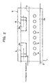
- Figures 1 and 2 show one furnace temperature control zone (S) of the catenary furnace 1 in accordance with this embodiment.
- a furnace casing 2 of the catenary furnace 1 of this embodiment is formed, as in the conventional example, so that the longitudinal dimension thereof is long and the transverse dimension (W) thereof is short so as to match the width of a material 3.
- the material 3 is heated while being conveyed in the longitudinal direction of the furnace casing 2 in the shape of a catenary curve within the furnace casing 2 heated by burners.
- the material 3 is conveyed so as to pass through a substantially central position in the height direction of the furnace casing 2.
- a plurality of lower burners 4 are arranged, and at the upper side of the material 3, alternate combustion type regenerative burners 5 and 6 are arranged.
- the material 3 is heated from the upper side and lower side by heat radiation from a furnace wall heated by the lower burners 4 and the regenerative burners 5 and 6 and their burner flames, and is subjected to heat treatment such as annealing and the like.
- the lower burners 4 are provided at intervals in the longitudinal direction of the furnace casing 2 in a lower part of a furnace side wall 2a considering a catenary sag of the material 3. As these lower burners 4, publicly known ordinary burners are used. These lower burners 4 are burned to the width direction of the furnace casing 2. Specifically, the lower burners 4 are fired so that the burner flames are directed in the transverse direction of the furnace casing 2, and also fired continuously or continually during the heating treatment of the conveyed material 3.
- the publicly known alternate combustion type regenerative burners 5 and 6, which have a pair of burners 5a, 5b, 6a and 6b burned alternately, are arranged so that the paired burners 5a, 5b, 6a and 6b face to each other along the longitudinal direction of the furnace casing 2, and are fired toward the longitudinal direction of the furnace casing 2, and in other words, they are burned such that the burner flames are directed toward the longitudinal direction of the furnace casing 2.
- the paired burners 5a, 5b, 6a and 6b are provided along the longitudinal direction of the furnace casing 2 so as to hold the furnace casing 2 therebetween in the transverse direction because they are provided in upper parts of the furnace side wall 2a.
- the paired burners 5a, 5b, 6a and 6b may be arranged so as to face to each other along the longitudinal direction of the furnace casing 2 by appropriately selecting the installation positions of the regenerative burners 5 and 6 with respect to the furnace casing 2.
- the two regenerative burners 5 and 6 are provided as one set so as to hold the furnace casing 2 therebetween.
- the paired burners 5a, 5b, 6a and 6b of the regenerative burners 5 and 6 perform combustion operation and exhaust operation alternately according to the switchover operation of the selector valve. Specifically, when the burners 5a and 6a in the upstream side in the conveying direction of the material 3 perform the combustion operation, the burners 5b and 6b in the downstream side perform the exhaust operation. When the burners 5b and 6b in the downstream side transfer to the combustion operation due to the switchover operation, the burners 5a and 6a in the upstream side perform the exhaust operation. Thereby, the furnace is operated while heat is stored in the heat reservoir and combustion air is heated.
- each heat input of them is controlled individually.
- a diffusion combustion type burner is preferably used for keeping the burner flame temperature low by means of mixing fuel and combustion air with each other within the furnace casing, so as to reduce the emission of NOx having high temperature dependency.
- furnace temperature control zones (Sa) being located at the upstream side of a plurality of the furnace temperature control zones (S) provided continuously along the conveying direction of the material 3, as shown in Figure 3, a plurality of burner combinations consisting of the regenerative burners 5 and 6 and the lower burners 4 are provided repeatedly along the longitudinal direction of the furnace casing 2.
- each heat input of the regenerative burners 5 and 6 and the lower burners 4 is controlled individually.
- furnace temperature control zones (Sb) located at the downstream side publicly known burners 7 arranged on a side are provided. These burners 7 are fired continuously during the heating treatment of the material 3.
- the catenary furnace 1 heated by burners continuously performs the heating treatment of the material 3 in a process in which the material 3 is conveyed along the longitudinal direction of the furnace casing 2 from the upstream side of the furnace temperature control zone (S) to the downstream side of the furnace temperature control zone (S) .
- the alternate combustion type regenerative burners 5 and 6 in the furnace temperature control zone (Sa) of the upstream side repeat the operation of alternately burning the paired burners 5a, 5b, 6a and 6b, and on the other hand, the lower burners 4 are burned continuously.
- the alternate combustion type regenerative burners 5 and 6 are fired toward the longitudinal direction of the furnace casing 2, these regenerative burners 5 and 6 can be burned with a necessary heat input without being restricted by the transverse dimension (W) of the furnace casing 2, as compared with the case where the regenerative burners are arranged toward the furnace width direction. Therefore, the number of the regenerative burners 5 and 6 can be decreased as the whole of the furnace casing structure.
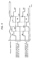
- the regenerative burners 5 and 6 are adopted, and on the other hand, the lower burners 4 fired continuously are provided on the lower side of the material 3, so that as shown in Figure 5, the lower burners 4 are burned continuously even for a period (Tb) during the switchover operation of the regenerative burners 5 and 6, by which the furnace temperature can be kept substantially constant.
- Tb a period during the switchover operation of the regenerative burners 5 and 6, by which the furnace temperature can be kept substantially constant.
- the maintenance service for auxiliary devices such as the selector valve and heat reservoir provided for the regenerative burners 5 and 6 can be lightened.
- the use of the regenerative burners 5 and 6, which are excellent in terms of measures against exhaust gas and energy saving, can enhance the compatibility with environment of the catenary furnace 1.
- the furnace temperature can be also controlled in the furnace width direction by controlling each heat input of these two regenerative burners 5 and 6 individually, and hence the temperature in the furnace width direction can be uniformed. Also, since each heat input of the regenerative burners 5 and 6 and the lower burners 4 is controlled individually, the furnace temperature distribution can be optimized.
- furnace temperature control zones (Sa) for arranging the regenerative burners 5 and 6 are provided, and the regenerative burners 5 and 6 are provided in plural numbers along the longitudinal direction of the furnace casing 2, the above-described operation and effects can be achieved not only as a single furnace temperature control zone (S) but also as the whole of the catenary furnace 1.
- the regenerative burners 5 and 6 and the lower burners 4 are provided in the furnace temperature control zone (Sa) on the upstream side in the conveying direction of the material 3, and side burners 7 fired continuously are provided in the furnace temperature control zone (Sb) on the downstream side in the conveying direction of the material 3, the material 3 can be heated properly by the regenerative burners 5 and 6 and the lower burners 4 on the upstream side on which the necessary heat input is great, so that the catenary furnace 1 can be configured rationally.
- the compatibility with environmental protection is high, the maintenance service is easy, and a material can be heated properly by restraining fluctuations in furnace temperature.
Landscapes
- Chemical & Material Sciences (AREA)
- Engineering & Computer Science (AREA)
- Materials Engineering (AREA)
- Thermal Sciences (AREA)
- Crystallography & Structural Chemistry (AREA)
- Mechanical Engineering (AREA)
- Physics & Mathematics (AREA)
- Metallurgy (AREA)
- Organic Chemistry (AREA)
- Heat Treatment Of Strip Materials And Filament Materials (AREA)
- Tunnel Furnaces (AREA)
- Waste-Gas Treatment And Other Accessory Devices For Furnaces (AREA)
- Air Supply (AREA)
Applications Claiming Priority (3)
| Application Number | Priority Date | Filing Date | Title |
|---|---|---|---|
| JP2003006356 | 2003-01-14 | ||
| JP2003006356A JP4278990B2 (ja) | 2003-01-14 | 2003-01-14 | カテナリ型炉 |
| PCT/JP2003/015394 WO2004063403A1 (ja) | 2003-01-14 | 2003-12-02 | カテナリ型炉 |
Publications (3)
| Publication Number | Publication Date |
|---|---|
| EP1584694A1 true EP1584694A1 (de) | 2005-10-12 |
| EP1584694A4 EP1584694A4 (de) | 2006-03-22 |
| EP1584694B1 EP1584694B1 (de) | 2012-09-05 |
Family
ID=32709059
Family Applications (1)
| Application Number | Title | Priority Date | Filing Date |
|---|---|---|---|
| EP03776019A Expired - Lifetime EP1584694B1 (de) | 2003-01-14 | 2003-12-02 | Durchhangofen |
Country Status (5)
| Country | Link |
|---|---|
| EP (1) | EP1584694B1 (de) |
| JP (1) | JP4278990B2 (de) |
| CN (1) | CN100419097C (de) |
| ES (1) | ES2394634T3 (de) |
| WO (1) | WO2004063403A1 (de) |
Families Citing this family (1)
| Publication number | Priority date | Publication date | Assignee | Title |
|---|---|---|---|---|
| US7452400B2 (en) * | 2005-07-07 | 2008-11-18 | The North American Manufacturing Company, Ltd. | Method and apparatus for melting metal |
Family Cites Families (11)
| Publication number | Priority date | Publication date | Assignee | Title |
|---|---|---|---|---|
| JPS5824491B2 (ja) * | 1980-07-16 | 1983-05-21 | 中外炉工業株式会社 | カテナリ−型炉の処理材搬送制御方法 |
| JPH0426722A (ja) * | 1990-05-18 | 1992-01-29 | Nkk Corp | ストリップ用カテナリー型連続炉 |
| JPH0554539A (ja) | 1991-08-20 | 1993-03-05 | Sony Corp | 記録方法及び記録媒体 |
| JPH0554539U (ja) * | 1991-12-19 | 1993-07-20 | 新日本製鐵株式会社 | 流動層連続熱処理ラインにおける鋼線通線用治具 |
| JP2788698B2 (ja) * | 1992-11-24 | 1998-08-20 | 日本ファーネス工業株式会社 | 低NOx燃焼法及びそのバーナ |
| JP3704177B2 (ja) * | 1995-05-16 | 2005-10-05 | 新日本製鐵株式会社 | 連続加熱装置および加熱方法 |
| JP3306580B2 (ja) * | 1997-03-25 | 2002-07-24 | 日本鋼管株式会社 | 蓄熱式バーナ炉 |
| JP4237842B2 (ja) * | 1998-03-05 | 2009-03-11 | 新日本製鐵株式会社 | 鋼片の連続加熱装置 |
| CN2372327Y (zh) * | 1999-05-11 | 2000-04-05 | 淄博中元工程有限公司 | 钢板弹簧的燃油(气)回火处理设备 |
| FR2794132B1 (fr) | 1999-05-27 | 2001-08-10 | Stein Heurtey | Perfectionnements apportes aux fours de rechauffage de produits siderurgiques |
| JP3962237B2 (ja) * | 2001-10-25 | 2007-08-22 | 新日本製鐵株式会社 | 連続式加熱炉 |
-
2003
- 2003-01-14 JP JP2003006356A patent/JP4278990B2/ja not_active Expired - Fee Related
- 2003-12-02 WO PCT/JP2003/015394 patent/WO2004063403A1/ja not_active Ceased
- 2003-12-02 ES ES03776019T patent/ES2394634T3/es not_active Expired - Lifetime
- 2003-12-02 EP EP03776019A patent/EP1584694B1/de not_active Expired - Lifetime
- 2003-12-02 CN CNB2003801061572A patent/CN100419097C/zh not_active Expired - Fee Related
Also Published As
| Publication number | Publication date |
|---|---|
| EP1584694A4 (de) | 2006-03-22 |
| JP2004218000A (ja) | 2004-08-05 |
| CN1726293A (zh) | 2006-01-25 |
| CN100419097C (zh) | 2008-09-17 |
| WO2004063403A1 (ja) | 2004-07-29 |
| EP1584694B1 (de) | 2012-09-05 |
| ES2394634T3 (es) | 2013-02-04 |
| JP4278990B2 (ja) | 2009-06-17 |
Similar Documents
| Publication | Publication Date | Title |
|---|---|---|
| JP2521386B2 (ja) | 鉄鋼加熱炉 | |
| EP1119733B1 (de) | Verfahren und vorrichtung zur gleichmässigen erzeugung von wärme in einem ofen | |
| CN105258504A (zh) | 一种隧道窑及其燃烧控制方法 | |
| US8083517B2 (en) | Method of operating a furnace | |
| EP1584694A1 (de) | Durchhangofen | |
| US5000158A (en) | Staged burning radiant tube | |
| JP4987689B2 (ja) | 直火型ローラーハース式連続熱処理炉 | |
| JP5211943B2 (ja) | 加熱炉の排気設備 | |
| JPH0797620A (ja) | 連続式加熱炉およびその燃焼方法 | |
| JP2006349281A (ja) | 連続式加熱炉、及びその燃焼制御方法 | |
| JP7115995B2 (ja) | 連続式加熱炉の炉圧制御方法、炉圧制御装置及び連続式加熱炉 | |
| JP4670715B2 (ja) | 連続式加熱炉群の被加熱物の振り分け方法 | |
| JP3417789B2 (ja) | 連続焼鈍炉 | |
| JPH08291328A (ja) | 連続加熱装置 | |
| JP2000028268A (ja) | 窯炉の熱交換システム及び熱交換方法 | |
| JP3924121B2 (ja) | リジェネレイティブバーナを備えた熱処理炉の炉温制御方法 | |
| JP3414942B2 (ja) | 加熱炉 | |
| JPH11132463A (ja) | 加熱炉用バーナ | |
| JP2755089B2 (ja) | 蓄熱式バーナを有する連続加熱炉の燃焼方法 | |
| JPH09126422A (ja) | 蓄熱式燃焼バーナおよびその燃焼方法 | |
| KR100317963B1 (ko) | 절환연소형 표면연소장치 | |
| JP2005213586A (ja) | 直接火焔加熱型無酸化炉のアフターバーン制御方法及び装置 | |
| JP2001208342A (ja) | ラジアントチューブバーナーの燃焼制御方法 | |
| JPH08120327A (ja) | 中間装入口を有する有効炉長が可変可能な加熱炉 | |
| JP2000097431A (ja) | 蓄熱式燃焼装置における排ガス吸引量制御方法 |
Legal Events
| Date | Code | Title | Description |
|---|---|---|---|
| PUAI | Public reference made under article 153(3) epc to a published international application that has entered the european phase |
Free format text: ORIGINAL CODE: 0009012 |
|
| 17P | Request for examination filed |
Effective date: 20050627 |
|
| AK | Designated contracting states |
Kind code of ref document: A1 Designated state(s): ES FI |
|
| A4 | Supplementary search report drawn up and despatched |
Effective date: 20060206 |
|
| 17Q | First examination report despatched |
Effective date: 20110727 |
|
| GRAP | Despatch of communication of intention to grant a patent |
Free format text: ORIGINAL CODE: EPIDOSNIGR1 |
|
| GRAS | Grant fee paid |
Free format text: ORIGINAL CODE: EPIDOSNIGR3 |
|
| GRAA | (expected) grant |
Free format text: ORIGINAL CODE: 0009210 |
|
| AK | Designated contracting states |
Kind code of ref document: B1 Designated state(s): ES FI |
|
| REG | Reference to a national code |
Ref country code: ES Ref legal event code: FG2A Ref document number: 2394634 Country of ref document: ES Kind code of ref document: T3 Effective date: 20130204 |
|
| PLBE | No opposition filed within time limit |
Free format text: ORIGINAL CODE: 0009261 |
|
| STAA | Information on the status of an ep patent application or granted ep patent |
Free format text: STATUS: NO OPPOSITION FILED WITHIN TIME LIMIT |
|
| 26N | No opposition filed |
Effective date: 20130606 |
|
| PGFP | Annual fee paid to national office [announced via postgrant information from national office to epo] |
Ref country code: FI Payment date: 20201222 Year of fee payment: 18 |
|
| PGFP | Annual fee paid to national office [announced via postgrant information from national office to epo] |
Ref country code: ES Payment date: 20210122 Year of fee payment: 18 |
|
| REG | Reference to a national code |
Ref country code: FI Ref legal event code: MAE |
|
| PG25 | Lapsed in a contracting state [announced via postgrant information from national office to epo] |
Ref country code: FI Free format text: LAPSE BECAUSE OF NON-PAYMENT OF DUE FEES Effective date: 20211202 |
|
| REG | Reference to a national code |
Ref country code: ES Ref legal event code: FD2A Effective date: 20230214 |
|
| PG25 | Lapsed in a contracting state [announced via postgrant information from national office to epo] |
Ref country code: ES Free format text: LAPSE BECAUSE OF NON-PAYMENT OF DUE FEES Effective date: 20211203 |