EP1583184A1 - Dichtelement für wasserdichten Verbinder und Formverfahren dafür - Google Patents
Dichtelement für wasserdichten Verbinder und Formverfahren dafür Download PDFInfo
- Publication number
- EP1583184A1 EP1583184A1 EP05007060A EP05007060A EP1583184A1 EP 1583184 A1 EP1583184 A1 EP 1583184A1 EP 05007060 A EP05007060 A EP 05007060A EP 05007060 A EP05007060 A EP 05007060A EP 1583184 A1 EP1583184 A1 EP 1583184A1
- Authority
- EP
- European Patent Office
- Prior art keywords
- sealing member
- cavity
- lip
- sealing
- circumferential surface
- Prior art date
- Legal status (The legal status is an assumption and is not a legal conclusion. Google has not performed a legal analysis and makes no representation as to the accuracy of the status listed.)
- Granted
Links
Images






Classifications
-
- H—ELECTRICITY
- H01—ELECTRIC ELEMENTS
- H01R—ELECTRICALLY-CONDUCTIVE CONNECTIONS; STRUCTURAL ASSOCIATIONS OF A PLURALITY OF MUTUALLY-INSULATED ELECTRICAL CONNECTING ELEMENTS; COUPLING DEVICES; CURRENT COLLECTORS
- H01R13/00—Details of coupling devices of the kinds covered by groups H01R12/70 or H01R24/00 - H01R33/00
- H01R13/46—Bases; Cases
- H01R13/52—Dustproof, splashproof, drip-proof, waterproof, or flameproof cases
- H01R13/521—Sealing between contact members and housing, e.g. sealing insert
-
- F—MECHANICAL ENGINEERING; LIGHTING; HEATING; WEAPONS; BLASTING
- F16—ENGINEERING ELEMENTS AND UNITS; GENERAL MEASURES FOR PRODUCING AND MAINTAINING EFFECTIVE FUNCTIONING OF MACHINES OR INSTALLATIONS; THERMAL INSULATION IN GENERAL
- F16J—PISTONS; CYLINDERS; SEALINGS
- F16J13/00—Covers or similar closure members for pressure vessels in general
- F16J13/02—Detachable closure members; Means for tightening closures
-
- F—MECHANICAL ENGINEERING; LIGHTING; HEATING; WEAPONS; BLASTING
- F16—ENGINEERING ELEMENTS AND UNITS; GENERAL MEASURES FOR PRODUCING AND MAINTAINING EFFECTIVE FUNCTIONING OF MACHINES OR INSTALLATIONS; THERMAL INSULATION IN GENERAL
- F16J—PISTONS; CYLINDERS; SEALINGS
- F16J15/00—Sealings
- F16J15/02—Sealings between relatively-stationary surfaces
- F16J15/021—Sealings between relatively-stationary surfaces with elastic packing
- F16J15/022—Sealings between relatively-stationary surfaces with elastic packing characterised by structure or material
- F16J15/024—Sealings between relatively-stationary surfaces with elastic packing characterised by structure or material the packing being locally weakened in order to increase elasticity
- F16J15/025—Sealings between relatively-stationary surfaces with elastic packing characterised by structure or material the packing being locally weakened in order to increase elasticity and with at least one flexible lip
-
- F—MECHANICAL ENGINEERING; LIGHTING; HEATING; WEAPONS; BLASTING
- F16—ENGINEERING ELEMENTS AND UNITS; GENERAL MEASURES FOR PRODUCING AND MAINTAINING EFFECTIVE FUNCTIONING OF MACHINES OR INSTALLATIONS; THERMAL INSULATION IN GENERAL
- F16J—PISTONS; CYLINDERS; SEALINGS
- F16J15/00—Sealings
- F16J15/02—Sealings between relatively-stationary surfaces
- F16J15/06—Sealings between relatively-stationary surfaces with solid packing compressed between sealing surfaces
- F16J15/062—Sealings between relatively-stationary surfaces with solid packing compressed between sealing surfaces characterised by the geometry of the seat
-
- H—ELECTRICITY
- H01—ELECTRIC ELEMENTS
- H01R—ELECTRICALLY-CONDUCTIVE CONNECTIONS; STRUCTURAL ASSOCIATIONS OF A PLURALITY OF MUTUALLY-INSULATED ELECTRICAL CONNECTING ELEMENTS; COUPLING DEVICES; CURRENT COLLECTORS
- H01R13/00—Details of coupling devices of the kinds covered by groups H01R12/70 or H01R24/00 - H01R33/00
- H01R13/44—Means for preventing access to live contacts
- H01R13/443—Dummy plugs
-
- H—ELECTRICITY
- H01—ELECTRIC ELEMENTS
- H01R—ELECTRICALLY-CONDUCTIVE CONNECTIONS; STRUCTURAL ASSOCIATIONS OF A PLURALITY OF MUTUALLY-INSULATED ELECTRICAL CONNECTING ELEMENTS; COUPLING DEVICES; CURRENT COLLECTORS
- H01R13/00—Details of coupling devices of the kinds covered by groups H01R12/70 or H01R24/00 - H01R33/00
- H01R13/46—Bases; Cases
- H01R13/52—Dustproof, splashproof, drip-proof, waterproof, or flameproof cases
- H01R13/5219—Sealing means between coupling parts, e.g. interfacial seal
Definitions
- an object of the invention is to provide a sealing member having an improved operability.
- the sealing member is centered by being guided by the inclined surface, and is at least partly inserted into the recessed portion while the wide and planar outer surface of the single lip portion is substantially uniformly resiliently compressed preferably over the substantially entire circumference. After the sealing member is substantially properly inserted, the outer surface of the lip is held substantially in close contact with the inner circumferential surface of the recessed portion preferably over the substantially entire circumference, thereby effectively sealing the recessed portion.
- the sealing member is substantially rotationally symmetric about its longitudinal axis.
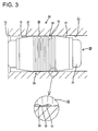
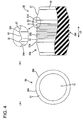
- the dummy plug 20 upon inserting the dummy plug 20 into the cavity 11, the dummy plug 20 is inserted with the top or outer surface 26 of the lip 25 substantially uniformly resiliently compressed preferably over the substantially entire circumference after being centered. Further, the fine undulated surface 30 preferably is formed in or at the top or outer surface 26 of the lip 25 to reduce a contact area between the top surface 26 of the lip 25 and the inner circumferential surface of the cavity 11, thereby decreasing a frictional resistance. Thus, an inserting force for the dummy plug 20 can be reduced to be smaller.
- the fine undulated surface 30 preferably is formed in the top or outer surface 26 of the single lip 25, it can be avoided, unlike the conventional general dummy plug having three lips, that the projecting ends of the lips successively come into contact with the opening edge of the cavity 11 upon inserting the dummy plug 20 into the cavity 11. Accordingly, the dummy plug 20 can be smoothly inserted, thereby protecting the lip 25 from being damaged or torn.
- the dummy plug 20 preferably is substantially centered by being guided by the inclined surface 27 and is inserted into a cavity 11 while the wide top or radially outer surface 26 of the single lip 25 is substantially uniformly resiliently compressed over the entire circumference, whereupon the top surface 26 is held substantially in close contact with the inner circumferential surface of the cavity 11 by the action of a resilient force, thereby sealing the cavity 11. Since the top or outer surface 26 preferably is formed with the fine undulated surface 30, a frictional resistance decreases and an area of contact also decreases. Thus, the dummy plug 20 can be smoothly inserted into the cavity 11 with a smaller force.
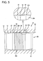
- a wide single lip or lip portion 76 is formed substantially preferably over the substantially entire width or extension, and an inclined surface 77 having a moderate downward (or radially inward) inclination is formed at an end of the lip 76 toward the mounting tube 74.
- the wide lip portion 76 preferably has a longitudinal extension of more than about 1/4, preferably of more than about 1/3, most preferably more than about half of the longitudinal extension of the plug main body 71.
- an undulated surface 78 having a short height or projecting distance is formed in the top or outer surface of the lip 76.
- the top or outer surface of the lip 76 of the waterproof rubber plug 70 is held in close contact with the inner circumferential surface of the entrance 62F of the cavity 61 F over the entire circumference by the action of a resilient force, thereby sealing the cavity 61 F.
- the waterproof rubber plug 70 is also used by being secured to an end of a wire W together with and behind a male terminal 63M and is inserted into an entrance 62M of a cavity 61 M to seal the cavity 61 M as the male terminal 63M is inserted into the cavity 61 M formed in a male housing 60M.
- the same functions and effects as in the case of being used in the female side can be obtained.
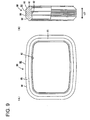
- a wide single lip or lip portion 84 is formed on the outer circumferential surface of the packing main body 81, and inclined surfaces 85 having a moderate downward or inward inclination (preferably of less than about 30°, preferably of less than about 20°, most preferably about 15° to the longitudinal direction LD) are formed at the opposite sides.
- the wide lip portion 84 preferably has a longitudinal extension of more than about 1/4, preferably of more than about 1/3, most preferably more than about half of the longitudinal extension of the packing main body 81.
- An undulated surface 86 having a short height or projecting distance is formed in the top or outer surface of the lip 84.
- the packing 80 is centered by being guided by the inclined surface 85 at the front side with respect to an inserting direction coming into contact with the opening edge of the projecting end of the receptacle 66, and is at least partly inserted into the receptacle 66 while the top or outer surface of the single lip 84 preferably is uniformly resiliently compressed over the substantially entire circumference.
- the packing 80 is resiliently squeezed preferably over the substantially entire circumference between the inner circumferential surface of the receptacle 66 and the outer circumferential surface of the tower portion 65, thereby providing sealing between the two housings 60F, 60M.
- the packing 80 of this embodiment is also formed with only one lip or lip portion 84 having the wide top or radially outer surface, a resiliently compressed volume is larger and a larger sealing force can be obtained. Further, upon at least partly inserting the packing 80 into the receptacle 66, the packing 80 is inserted with the top or outer surface of the lip 84 uniformly resiliently compressed preferably over the substantially entire circumference after being centered by the inclined surface 85. Further, the fine undulated surface 86 is formed in the top or outer surface of the lip 84 to reduce a contact area between the top surface of the lip 84 and the inner circumferential surface of the receptacle 66, thereby decreasing a frictional resistance. Thus, an inserting force for the packing 80 can be suppressed to be smaller and, in its turn, a connecting force for the female and male housings 60F, 60M can be suppressed to be smaller.
Landscapes
- Engineering & Computer Science (AREA)
- General Engineering & Computer Science (AREA)
- Mechanical Engineering (AREA)
- Physics & Mathematics (AREA)
- Geometry (AREA)
- Connector Housings Or Holding Contact Members (AREA)
- Gasket Seals (AREA)
Applications Claiming Priority (2)
| Application Number | Priority Date | Filing Date | Title |
|---|---|---|---|
| JP2004109831 | 2004-04-02 | ||
| JP2004109831A JP4200930B2 (ja) | 2004-04-02 | 2004-04-02 | 防水コネクタ用シール部材 |
Publications (2)
| Publication Number | Publication Date |
|---|---|
| EP1583184A1 true EP1583184A1 (de) | 2005-10-05 |
| EP1583184B1 EP1583184B1 (de) | 2008-05-07 |
Family
ID=34836615
Family Applications (1)
| Application Number | Title | Priority Date | Filing Date |
|---|---|---|---|
| EP05007060A Expired - Lifetime EP1583184B1 (de) | 2004-04-02 | 2005-03-31 | Dichtelement für wasserdichten Verbinder und Formverfahren dafür |
Country Status (5)
| Country | Link |
|---|---|
| US (1) | US7338320B2 (de) |
| EP (1) | EP1583184B1 (de) |
| JP (1) | JP4200930B2 (de) |
| CN (1) | CN100468879C (de) |
| DE (1) | DE602005006459D1 (de) |
Families Citing this family (24)
| Publication number | Priority date | Publication date | Assignee | Title |
|---|---|---|---|---|
| JP4512626B2 (ja) * | 2007-09-28 | 2010-07-28 | 日立オートモティブシステムズ株式会社 | 車載電子機器 |
| JP5614793B2 (ja) * | 2008-12-12 | 2014-10-29 | 矢崎総業株式会社 | パッキンの誤組付け防止構造 |
| JP5417954B2 (ja) * | 2009-04-09 | 2014-02-19 | 住友電装株式会社 | 防水コネクタ |
| PL2320527T3 (pl) * | 2009-11-09 | 2012-12-31 | Schaefer Werkzeug & Sonderma | Maszyna do montażu przepustów |
| CN101813257B (zh) * | 2010-04-07 | 2014-08-27 | 海洋王照明科技股份有限公司 | 一种照明装置 |
| JP5471947B2 (ja) * | 2010-08-02 | 2014-04-16 | 住友電装株式会社 | ゴム栓およびダミー栓 |
| US8485834B2 (en) * | 2011-05-12 | 2013-07-16 | International Business Machines Corporation | Mitigating electromagnetic interference using dummy plugs |
| JP5741861B2 (ja) * | 2012-01-31 | 2015-07-01 | アイコム株式会社 | 電子機器の電極構造および携帯電子機器 |
| JP6134303B2 (ja) * | 2014-10-07 | 2017-05-24 | 矢崎総業株式会社 | 防水栓 |
| DE102014118685A1 (de) * | 2014-12-15 | 2016-06-16 | Erni Production Gmbh & Co. Kg | Hermetisch dichtender Steckverbinder |
| JP6601242B2 (ja) * | 2016-01-29 | 2019-11-06 | 住友電装株式会社 | コネクタ |
| JP6551248B2 (ja) * | 2016-01-29 | 2019-07-31 | 住友電装株式会社 | コネクタ |
| EP3708882A4 (de) * | 2017-11-10 | 2021-08-04 | Nok Corporation | Dichtung |
| US11283211B2 (en) | 2018-05-18 | 2022-03-22 | Yazaki North America, Inc. | Electrical connector assembly with plug and cavity assembly and method of ultrasonically welding |
| JP7011532B2 (ja) * | 2018-05-21 | 2022-01-26 | 日本航空電子工業株式会社 | ダミーピン |
| CN111065011A (zh) * | 2018-10-16 | 2020-04-24 | 北京小米移动软件有限公司 | 密封部件、密封结构及终端设备 |
| JP7056525B2 (ja) * | 2018-11-15 | 2022-04-19 | 株式会社デンソー | 防水筐体 |
| JP7347146B2 (ja) * | 2019-11-15 | 2023-09-20 | 富士通オプティカルコンポーネンツ株式会社 | 光モジュール |
| JP7634342B2 (ja) * | 2020-01-10 | 2025-02-21 | 川崎重工業株式会社 | 気密端子、及びそれを備えるタンクバルブ装置 |
| CN111786147A (zh) * | 2020-07-13 | 2020-10-16 | 江苏协昌电子科技股份有限公司 | 一种接线座 |
| EP3979445A1 (de) | 2020-09-30 | 2022-04-06 | Corning Research & Development Corporation | Dichtungselement |
| JP7581978B2 (ja) * | 2021-03-08 | 2024-11-13 | 住友電装株式会社 | インレット組立体 |
| CN113352530B (zh) * | 2021-04-30 | 2022-09-09 | 河南方亿密封科技有限公司 | 一种橡胶密封圈的生产工艺 |
| JP2024053883A (ja) * | 2022-10-04 | 2024-04-16 | タイコエレクトロニクスジャパン合同会社 | シール部材およびコネクタ組立体 |
Citations (4)
| Publication number | Priority date | Publication date | Assignee | Title |
|---|---|---|---|---|
| US5328382A (en) * | 1993-04-13 | 1994-07-12 | Molex Incorporated | Electrical connector with external seal and internal terminal retaining means |
| EP0694993A1 (de) * | 1994-07-27 | 1996-01-31 | Sumitomo Wiring Systems, Ltd. | Wasserfeste Dichtung für Verbinder und Verfahren für die Herstellung |
| US5704796A (en) * | 1995-11-16 | 1998-01-06 | Swenson; Steven R. | Tearaway dummy plug for power cord receptacles |
| US20010007802A1 (en) * | 1999-10-28 | 2001-07-12 | Quality Synthetic Rubber | Dummy plug for wiring harness |
Family Cites Families (3)
| Publication number | Priority date | Publication date | Assignee | Title |
|---|---|---|---|---|
| JP3219755B2 (ja) | 1989-12-08 | 2001-10-15 | ソニー株式会社 | 半導体装置の製造方法 |
| JPH11354201A (ja) * | 1998-06-10 | 1999-12-24 | Yazaki Corp | 防水コネクタ |
| US6595789B2 (en) * | 2000-10-20 | 2003-07-22 | Autonetworks Technologies, Ltd. | Electronic unit, shield cable connecting structure, connecting method, wires waterproof-connecting structure, and method |
-
2004
- 2004-04-02 JP JP2004109831A patent/JP4200930B2/ja not_active Expired - Lifetime
-
2005
- 2005-03-31 US US11/096,100 patent/US7338320B2/en not_active Expired - Lifetime
- 2005-03-31 DE DE602005006459T patent/DE602005006459D1/de not_active Expired - Lifetime
- 2005-03-31 EP EP05007060A patent/EP1583184B1/de not_active Expired - Lifetime
- 2005-04-04 CN CNB2005100640032A patent/CN100468879C/zh not_active Expired - Lifetime
Patent Citations (4)
| Publication number | Priority date | Publication date | Assignee | Title |
|---|---|---|---|---|
| US5328382A (en) * | 1993-04-13 | 1994-07-12 | Molex Incorporated | Electrical connector with external seal and internal terminal retaining means |
| EP0694993A1 (de) * | 1994-07-27 | 1996-01-31 | Sumitomo Wiring Systems, Ltd. | Wasserfeste Dichtung für Verbinder und Verfahren für die Herstellung |
| US5704796A (en) * | 1995-11-16 | 1998-01-06 | Swenson; Steven R. | Tearaway dummy plug for power cord receptacles |
| US20010007802A1 (en) * | 1999-10-28 | 2001-07-12 | Quality Synthetic Rubber | Dummy plug for wiring harness |
Also Published As
| Publication number | Publication date |
|---|---|
| CN1677756A (zh) | 2005-10-05 |
| JP4200930B2 (ja) | 2008-12-24 |
| CN100468879C (zh) | 2009-03-11 |
| US20050179209A1 (en) | 2005-08-18 |
| EP1583184B1 (de) | 2008-05-07 |
| DE602005006459D1 (de) | 2008-06-19 |
| US7338320B2 (en) | 2008-03-04 |
| JP2005294146A (ja) | 2005-10-20 |
Similar Documents
| Publication | Publication Date | Title |
|---|---|---|
| EP1583184B1 (de) | Dichtelement für wasserdichten Verbinder und Formverfahren dafür | |
| CN103378445B (zh) | 连接器 | |
| US6443764B2 (en) | Watertight connector, a connector housing and a waterproof member therefor | |
| US6464522B2 (en) | Connector with terminal protective plate having internal and external sealing members | |
| US7252547B2 (en) | Connector | |
| EP0599329B1 (de) | Kabeldichtung für wasserdichte elektrische Verbinder | |
| US20110045696A1 (en) | Connector | |
| CN110518399A (zh) | 仿真销 | |
| US9570839B2 (en) | Waterproof connector | |
| EP1137111B1 (de) | Ein wasserdichter Verbinder und ein Dichtelement | |
| JP2002329554A (ja) | コネクタ | |
| JP5818100B2 (ja) | 防水コネクタ | |
| US20230208076A1 (en) | Connector | |
| US6609932B2 (en) | Watertight connector and a method for mounting it | |
| US6752644B2 (en) | Watertight connector | |
| JP2586314Y2 (ja) | 防水コネクタ | |
| JP2001351717A (ja) | コネクタ | |
| JP2004139758A (ja) | コネクタ | |
| JP3752982B2 (ja) | 防水コネクタ | |
| JP3551904B2 (ja) | コネクタ | |
| JP3090044B2 (ja) | 防水コネクタ用シールゴム栓 | |
| JP5696893B2 (ja) | 防水コネクタ | |
| JP3778023B2 (ja) | 防水コネクタ | |
| JP2011003356A (ja) | 防水コネクタ | |
| JP2004363068A (ja) | 防水コネクタ用ゴム栓 |
Legal Events
| Date | Code | Title | Description |
|---|---|---|---|
| PUAI | Public reference made under article 153(3) epc to a published international application that has entered the european phase |
Free format text: ORIGINAL CODE: 0009012 |
|
| 17P | Request for examination filed |
Effective date: 20050407 |
|
| AK | Designated contracting states |
Kind code of ref document: A1 Designated state(s): AT BE BG CH CY CZ DE DK EE ES FI FR GB GR HU IE IS IT LI LT LU MC NL PL PT RO SE SI SK TR |
|
| AX | Request for extension of the european patent |
Extension state: AL BA HR LV MK YU |
|
| AKX | Designation fees paid |
Designated state(s): DE FR |
|
| GRAP | Despatch of communication of intention to grant a patent |
Free format text: ORIGINAL CODE: EPIDOSNIGR1 |
|
| RIN1 | Information on inventor provided before grant (corrected) |
Inventor name: KOBAYASHI, YUTAKAC/O SUMITOMO WIRING SYSTEMS, LTD. |
|
| GRAS | Grant fee paid |
Free format text: ORIGINAL CODE: EPIDOSNIGR3 |
|
| GRAA | (expected) grant |
Free format text: ORIGINAL CODE: 0009210 |
|
| AK | Designated contracting states |
Kind code of ref document: B1 Designated state(s): DE FR |
|
| REF | Corresponds to: |
Ref document number: 602005006459 Country of ref document: DE Date of ref document: 20080619 Kind code of ref document: P |
|
| REG | Reference to a national code |
Ref country code: DE Ref legal event code: R096 Ref document number: 602005006459 Country of ref document: DE Effective date: 20080619 |
|
| PLBE | No opposition filed within time limit |
Free format text: ORIGINAL CODE: 0009261 |
|
| STAA | Information on the status of an ep patent application or granted ep patent |
Free format text: STATUS: NO OPPOSITION FILED WITHIN TIME LIMIT |
|
| 26N | No opposition filed |
Effective date: 20090210 |
|
| REG | Reference to a national code |
Ref country code: DE Ref legal event code: R097 Ref document number: 602005006459 Country of ref document: DE Effective date: 20090210 |
|
| REG | Reference to a national code |
Ref country code: FR Ref legal event code: PLFP Year of fee payment: 12 |
|
| REG | Reference to a national code |
Ref country code: FR Ref legal event code: PLFP Year of fee payment: 13 |
|
| REG | Reference to a national code |
Ref country code: DE Ref legal event code: R084 Ref document number: 602005006459 Country of ref document: DE |
|
| REG | Reference to a national code |
Ref country code: FR Ref legal event code: PLFP Year of fee payment: 14 |
|
| PGFP | Annual fee paid to national office [announced via postgrant information from national office to epo] |
Ref country code: DE Payment date: 20220203 Year of fee payment: 18 |
|
| P01 | Opt-out of the competence of the unified patent court (upc) registered |
Effective date: 20230517 |
|
| REG | Reference to a national code |
Ref country code: DE Ref legal event code: R119 Ref document number: 602005006459 Country of ref document: DE |
|
| PG25 | Lapsed in a contracting state [announced via postgrant information from national office to epo] |
Ref country code: DE Free format text: LAPSE BECAUSE OF NON-PAYMENT OF DUE FEES Effective date: 20231003 |
|
| PGFP | Annual fee paid to national office [announced via postgrant information from national office to epo] |
Ref country code: FR Payment date: 20240213 Year of fee payment: 20 |