EP1583132A1 - Elektronenkanone fürKathodenstrahlröhre mit verbessertem Strahlformungsbereich - Google Patents
Elektronenkanone fürKathodenstrahlröhre mit verbessertem Strahlformungsbereich Download PDFInfo
- Publication number
- EP1583132A1 EP1583132A1 EP05102213A EP05102213A EP1583132A1 EP 1583132 A1 EP1583132 A1 EP 1583132A1 EP 05102213 A EP05102213 A EP 05102213A EP 05102213 A EP05102213 A EP 05102213A EP 1583132 A1 EP1583132 A1 EP 1583132A1
- Authority
- EP
- European Patent Office
- Prior art keywords
- electrode
- electron gun
- expansion
- cathode
- gun
- Prior art date
- Legal status (The legal status is an assumption and is not a legal conclusion. Google has not performed a legal analysis and makes no representation as to the accuracy of the status listed.)
- Withdrawn
Links
- 238000007493 shaping process Methods 0.000 title claims abstract description 4
- 229910045601 alloy Inorganic materials 0.000 claims abstract description 19
- 239000000956 alloy Substances 0.000 claims abstract description 19
- 238000010894 electron beam technology Methods 0.000 claims abstract description 17
- 230000001590 oxidative effect Effects 0.000 claims abstract description 15
- 229910000831 Steel Inorganic materials 0.000 claims description 28
- 239000000463 material Substances 0.000 claims description 28
- 239000010959 steel Substances 0.000 claims description 28
- 229910001220 stainless steel Inorganic materials 0.000 claims description 14
- 239000010935 stainless steel Substances 0.000 claims description 12
- 229910002555 FeNi Inorganic materials 0.000 claims description 7
- 230000005672 electromagnetic field Effects 0.000 claims description 4
- 238000010438 heat treatment Methods 0.000 description 24
- 239000011521 glass Substances 0.000 description 18
- 230000006698 induction Effects 0.000 description 14
- 230000003647 oxidation Effects 0.000 description 9
- 238000007254 oxidation reaction Methods 0.000 description 9
- XEEYBQQBJWHFJM-UHFFFAOYSA-N iron Substances [Fe] XEEYBQQBJWHFJM-UHFFFAOYSA-N 0.000 description 8
- 229910052742 iron Inorganic materials 0.000 description 6
- 229910001092 metal group alloy Inorganic materials 0.000 description 6
- 238000005086 pumping Methods 0.000 description 6
- 239000002184 metal Substances 0.000 description 5
- 229910052751 metal Inorganic materials 0.000 description 5
- 238000007789 sealing Methods 0.000 description 4
- 230000000694 effects Effects 0.000 description 3
- OAICVXFJPJFONN-UHFFFAOYSA-N Phosphorus Chemical compound [P] OAICVXFJPJFONN-UHFFFAOYSA-N 0.000 description 2
- 238000010586 diagram Methods 0.000 description 2
- 238000004519 manufacturing process Methods 0.000 description 2
- MYMOFIZGZYHOMD-UHFFFAOYSA-N Dioxygen Chemical compound O=O MYMOFIZGZYHOMD-UHFFFAOYSA-N 0.000 description 1
- 230000001133 acceleration Effects 0.000 description 1
- 230000004913 activation Effects 0.000 description 1
- QVGXLLKOCUKJST-UHFFFAOYSA-N atomic oxygen Chemical compound [O] QVGXLLKOCUKJST-UHFFFAOYSA-N 0.000 description 1
- 230000015572 biosynthetic process Effects 0.000 description 1
- 239000003086 colorant Substances 0.000 description 1
- 230000006835 compression Effects 0.000 description 1
- 238000007906 compression Methods 0.000 description 1
- 238000005336 cracking Methods 0.000 description 1
- 238000007872 degassing Methods 0.000 description 1
- 230000001627 detrimental effect Effects 0.000 description 1
- 229910001882 dioxygen Inorganic materials 0.000 description 1
- 238000010494 dissociation reaction Methods 0.000 description 1
- 230000005593 dissociations Effects 0.000 description 1
- 229910000833 kovar Inorganic materials 0.000 description 1
- 239000000696 magnetic material Substances 0.000 description 1
- 238000005259 measurement Methods 0.000 description 1
- 239000000155 melt Substances 0.000 description 1
- 150000002739 metals Chemical class 0.000 description 1
- 239000001301 oxygen Substances 0.000 description 1
- 229910052760 oxygen Inorganic materials 0.000 description 1
- 239000002574 poison Substances 0.000 description 1
- 231100000614 poison Toxicity 0.000 description 1
- 208000024891 symptom Diseases 0.000 description 1
Images


Classifications
-
- E—FIXED CONSTRUCTIONS
- E02—HYDRAULIC ENGINEERING; FOUNDATIONS; SOIL SHIFTING
- E02D—FOUNDATIONS; EXCAVATIONS; EMBANKMENTS; UNDERGROUND OR UNDERWATER STRUCTURES
- E02D29/00—Independent underground or underwater structures; Retaining walls
- E02D29/02—Retaining or protecting walls
- E02D29/025—Retaining or protecting walls made up of similar modular elements stacked without mortar
-
- H—ELECTRICITY
- H01—ELECTRIC ELEMENTS
- H01J—ELECTRIC DISCHARGE TUBES OR DISCHARGE LAMPS
- H01J29/00—Details of cathode-ray tubes or of electron-beam tubes of the types covered by group H01J31/00
- H01J29/46—Arrangements of electrodes and associated parts for generating or controlling the ray or beam, e.g. electron-optical arrangement
- H01J29/48—Electron guns
- H01J29/484—Eliminating deleterious effects due to thermal effects, electrical or magnetic fields; Preventing unwanted emission
-
- E—FIXED CONSTRUCTIONS
- E02—HYDRAULIC ENGINEERING; FOUNDATIONS; SOIL SHIFTING
- E02D—FOUNDATIONS; EXCAVATIONS; EMBANKMENTS; UNDERGROUND OR UNDERWATER STRUCTURES
- E02D17/00—Excavations; Bordering of excavations; Making embankments
- E02D17/20—Securing of slopes or inclines
- E02D17/205—Securing of slopes or inclines with modular blocks, e.g. pre-fabricated
-
- E—FIXED CONSTRUCTIONS
- E02—HYDRAULIC ENGINEERING; FOUNDATIONS; SOIL SHIFTING
- E02D—FOUNDATIONS; EXCAVATIONS; EMBANKMENTS; UNDERGROUND OR UNDERWATER STRUCTURES
- E02D29/00—Independent underground or underwater structures; Retaining walls
- E02D29/02—Retaining or protecting walls
- E02D29/0258—Retaining or protecting walls characterised by constructional features
- E02D29/0266—Retaining or protecting walls characterised by constructional features made up of preformed elements
-
- E—FIXED CONSTRUCTIONS
- E02—HYDRAULIC ENGINEERING; FOUNDATIONS; SOIL SHIFTING
- E02D—FOUNDATIONS; EXCAVATIONS; EMBANKMENTS; UNDERGROUND OR UNDERWATER STRUCTURES
- E02D2200/00—Geometrical or physical properties
- E02D2200/16—Shapes
- E02D2200/1607—Shapes round, e.g. circle
-
- E—FIXED CONSTRUCTIONS
- E02—HYDRAULIC ENGINEERING; FOUNDATIONS; SOIL SHIFTING
- E02D—FOUNDATIONS; EXCAVATIONS; EMBANKMENTS; UNDERGROUND OR UNDERWATER STRUCTURES
- E02D2600/00—Miscellaneous
- E02D2600/20—Miscellaneous comprising details of connection between elements
Definitions
- the invention relates to an electron gun and, in particular, an electron gun which is more resistant to the emission problem caused by oxidation of the electrodes G1 and/or G2 when it is being sealed into the tube (mount-sealing) and more resistant to the problem of thermomechanically induced remanent deformation caused by heating in the course of the radiofrequency induction (RF heating) carried out when pumping the cathode-ray tube.
- RF heating radiofrequency induction
- the problem is that the characteristics of certain electrodes may become modified during the manufacture of a cathode-ray tube, and may consequently modify certain characteristics of the tube.
- radiofrequency induction heating of the gun is carried out by means of an electromagnetic self-inductance with a view to degassing the gun.
- the metal parts of the gun are heated and therefore expand, respectively as a function of their temperature and the coefficient of thermal expansion of their material. Mechanical stresses are created because the expansions are not balanced between the parts, which are rigidly connected to two sintered glass bars VF1 and VF2 constituting the framework of the gun.
- the hottest parts of the gun are in this case the electrodes G2 (heated to a temperature of about 750°C), G3 (heated to a temperature of about 790°C) and G1 (heated to a temperature of about 680°C).
- the drawback of the mechanical stresses is a remanent deformation of certain parts of the gun, and in the worst case cracking or fracture of the two sintered glass bars VF1 and VF2 (especially if they experience mechanical stresses when the gun is being cooled after the end of the RF heating).
- the cost of the gun depends in particular on the cost of the materials constituting the parts of the gun.
- Alloys having low coefficients of thermal expansion such as the metal alloys of the family FeNi (that is to say in which Fe and Ni make up more than 95% of the mass) and the metal alloys of the family FeNiCo (that is to say in which Fe, Ni and Co make up more than 95% of the mass) are more expensive than stainless steels.
- Electron guns in which the electrodes are made of FeNi, and which for example have the characteristics summarised in the table below, are known: Tube startup, 6.3V being applied RF induction heating of the gun Selected material Expansible width between the glass bars T° stabilized Coeffici ent of expansio n of the material Expansion at startup ( ⁇ m) T° stabilized Coeff. of expansion of the material RF expansion ( ⁇ m) Units mn °C 10 -6 /°C ⁇ m °C 10 -6 /°C ⁇ m G4 et seq.
- Figure 2 represents a graph indicating the expansions of the electrodes G1 to G4 and of the cathode supports in such an electron gun during RF induction heating and at startup of the gun. It can be seen that such an electron gun exhibits expansions which are acceptable and, in particular, approximately uniform for the various electrodes in RF.
- the electrodes G1 and G2 are not resistant to the oxidation and present a strong risk of having poor electron emission.
- Another type of electron gun such as the Toshiba and Matsushita guns in particular, uses the material "Kovar” (FeNiCo alloy) for G1 and G2.
- This alloy has a low coefficient of thermal expansion but cannot withstand the oxidation as much a stainless steel, and it is more expensive.
- a conventional solution to the problem of oxidation is to use a conventional stainless steel from the family of austenitic steels, such as the Type 305 steel whose UNS designation is S30500, for the electrodes G1 and G2.
- the electron gun will not be resistant to the problem of thermomechanically induced remanent deformation caused by heating in the course of the radiofrequency induction (RF heating) for pumping.
- the gun then has a mediocre "CTC" (colour temperature change).
- the known solution is to use alloys having lower coefficients of thermal expansion for the electrodes G1, G2 and G3, and more specifically metal alloys whose coefficient of expansion between 20°C and 300°C lies between 3 10 -6 /°C and 7 10 -6 /°C.
- an electron gun When wishing to provide the gun with an acceptable "CTC" (colour temperature change), for example as described in US Patent 4492894, an electron gun may be provided in which the materials of the successive electrodes of the gun are selected so as to balance the expansions of these electrodes in the steady-state regime corresponding to the time at which the filaments and the cathodes have reached their rated temperatures (generally with 6.3 V across the terminals of the filaments). The hottest electrodes will therefore have the lowest coefficients of expansion.
- CTC colour temperature change
- the electrode G3 will have a higher coefficient of thermal expansion than G2 even though G3 is already hotter then G2, and the electrode G2 will have a higher coefficient of thermal expansion then G1 even though G2 is already hotter then G1.
- the electron gun will not therefore be resistant to the problem of thermomechanically induced remanent deformation caused by heating in the course of the radiofrequency induction (RF heating) for pumping.
- RF heating radiofrequency induction
- US Patent 4468588 addresses the CTC problem.
- This patent describes a solution in which the cathode supports minimize the deformations of the electrode G1 with respect to the cathodes.
- This document does not resolve the emission problem caused by oxidation of the electrodes G1 and/or G2 when it is being sealed into the tube (mount-sealing), nor the problem of making the gun more resistant to the thermomechanically induced remanent deformations caused by heating in the course of the radiofrequency induction (RF heating) carried out when pumping the cathode-ray tube.
- RF heating radiofrequency induction
- the invention therefore relates to an electron gun making it possible to resolve these problems.
- the invention therefore relates to an electron gun, comprising at least:
- the first and second electrodes are made of a non-oxidizing alloy whose coefficient of expansion between 20°C and 300°C lies between 4 10 -6 /°C and 13 10 -6 /°C .
- the third electrode may be made of FeNi, and in particular FeNi48, whose coefficient of expansion differs little from that of the first and second electrodes.
- the third electrode is made of a non-oxidizing alloy whose coefficient of expansion between 20°C and 300°C lies between 4 10 -6 /°C and 13 10 -6 /°C .
- the cathode supports are made of a non-oxidizing alloy whose coefficient of expansion between 20°C and 300°C lies between 4 10 -6 /°C and 13 10 -6 /°C.
- the fourth electrode (G4) may also be made of a stainless steel, either from the common family of austenitic steels or from the family of ferritic steels, such as the subfamily referred to as Type 430 whose UNS designation is S43000.
- the said non-oxidizing alloy whose coefficient of expansion between 20°C and 300°C lies between 4 10 -6 /°C and 13 10 -6 /°C is preferably a steel from the family of ferritic steels, such as the subfamily referred to as Type 430 whose UNS designation is S43000.
- the third electrode G3 also preferably includes a piece of FeNi material which can delimit the electromagnetic field of the deflector.
- a conventional television tube has a substantially flat rectangular front panel or screen.
- the screen is provided on its inner face with a mosaic of phosphor spots or pixels which, when stimulated by an electron beam, emit light that may be blue, green or red depending on which phosphor is stimulated.
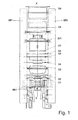
- An electron gun as represented in Figure 1 sealed in the envelope of the tube, is directed at the centre of the screen and makes it possible to emit the electron beam towards the various points on the screen through a perforated mask (or shadow mask).
- the electron gun allows the electron beam to be focussed on the inner face of the screen carrying the phosphors.
- the electron gun in Figure 1 therefore has:
- the invention relates to an electron gun structure characterized by the use of particular metal alloys for certain parts.
- the object of the invention is to obtain an electron gun:
- the invention therefore proposes that, for the electrodes G1 and G2, a non-oxidizing alloy should be used whose coefficient of expansion between 20°C and 300°C lies between 4 10 -6 /°C and 13 10 -6 /°C (for example between 7 10 -6 /°C and 13 10 -6 /°C).
- This alloy is preferably a stainless steel from the family of ferritic steels, preferably from the subfamily referred to as Type 430 whose designation in the UNS standard is S43000, and which will be referred to as Inox 430 steel in the rest of the description.
- This Inox 430 steel is described in the document Atlas Stainless Steel Grades from the AISI (American Iron and Steel Institute).
- Such a metal presents the advantages of having a low coefficient of thermal expansion, of being inexpensive and of not oxidizing.
- This material was chosen for the electrodes G1 and G2 because these electrodes are the ones most liable to be both oxidized and bombarded by the electron beam.
- the table below summarises the characteristics of such an electron gun.
- the electrode G3 is, for example, made of FeNi48.
- Figure 3a furthermore illustrates the expansions of the electrodes G1 to G4 and of the cathode supports, such as SK1, by diagrams.
- the expansions of these various elements are substantially equivalent in RF induction heating and at startup of the gun.
- the expansions of the elements connected to the sintered glass bars VF1 and VF2 may therefore be regarded as substantially homogeneous. There is therefore little remanent deformation of the metal parts and little risk of creating stresses in the glass bars VF1 and VF2.
- Such an electron gun is thus advantageous because of the homogeneous expansions of the electrodes G1 to G4 and of the electrode supports, the low risk of oxidizing the electrodes G1 and G2, its acceptable CTC (colour temperature change) and for economic reasons.
- the electrode G3 is liable to be bombarded by the electron beam, but is exposed very little to oxidation during manufacture of the tube because it is not heated greatly during the sealing.
- the part(s) of G3 which are connected to the 2 sintered glass bars VF1 and VF2 may be made of a non-oxidizing alloy whose coefficient of expansion between 20°C and 300°C lies between 4 10 -6 /°C and 13 10 -6 /°C (for example, 7 10 -6 /°C and 13 10 -6 /°C). It may, for example, be a non-oxidizing metal alloy of the family of steels such as Inox 430 steel.
- the third electrode G3 also includes a piece of a material which can delimit the electromagnetic field of the deflector, for example an "insert" piece of FeNi48.
- Figure 4 represents an exemplary embodiment of such an electrode G3 made of Inox 430 steel provided with a piece of FeNi48.
- the table below illustrates the characteristics of an electron gun in which the electrodes G1 to G3 are made of Inox 430 steel.
- FIGs in Figure 3b illustrate the expansions of the electrodes G1 to G4 and of the cathode supports in this alternative embodiment.
- the expansions of these elements appear homogeneous.
- the electrodes G1 and G2 are made of a material as defined above (Inox 430 steel) and an alloy with a low coefficient of thermal expansion is used for the cathode supports.
- This alloy need not be resistant to oxidation since the supports are never bombarded by the electron beam, but it is preferable to use a stainless steel from the family of ferritic steels, namely the family referred to as Type 430 whose US designation is S43000.
- the table below gives the characteristics of such an electron gun: Tube startup, 6.3V being applied RF induction heating of the gun Selected material Expansible width between the glass bars T° stabilized Coefficient of expansion of the material Expansion at startup ( ⁇ m) T° stabilized Coeff.
- Figure 3c represents the expansions of the electrodes G1 to G4 and of the cathode supports in this variant. These expansions appear homogeneous for the various elements. As before, there is a good resistance to oxidation and an acceptable CTC (sufficient flexibility being imparted to the cathode supports such as SK1).
- the electrodes G1 to G3 and the cathode supports are made of Inox 430 steel.
- the electrode G4 it is sufficient to use an inexpensive material such as a stainless steel either from the common family of austenitic steels or from the family of ferritic steels, such as the subfamily referred to as Type 430 whose UNS designation is S43000.
- an inexpensive material such as a stainless steel either from the common family of austenitic steels or from the family of ferritic steels, such as the subfamily referred to as Type 430 whose UNS designation is S43000.
- the electrodes G4 et seq. may be made of this material.
Landscapes
- Engineering & Computer Science (AREA)
- Mining & Mineral Resources (AREA)
- Life Sciences & Earth Sciences (AREA)
- General Life Sciences & Earth Sciences (AREA)
- Paleontology (AREA)
- Civil Engineering (AREA)
- General Engineering & Computer Science (AREA)
- Structural Engineering (AREA)
- Environmental & Geological Engineering (AREA)
- Electrodes For Cathode-Ray Tubes (AREA)
- Microwave Tubes (AREA)
Applications Claiming Priority (2)
| Application Number | Priority Date | Filing Date | Title |
|---|---|---|---|
| FR0450617A FR2868597B1 (fr) | 2004-03-30 | 2004-03-30 | Canon a electrons pour tube a rayons cathodiques a zone de formation des faisceaux amelioree |
| FR0450617 | 2004-03-30 |
Publications (1)
| Publication Number | Publication Date |
|---|---|
| EP1583132A1 true EP1583132A1 (de) | 2005-10-05 |
Family
ID=34878498
Family Applications (1)
| Application Number | Title | Priority Date | Filing Date |
|---|---|---|---|
| EP05102213A Withdrawn EP1583132A1 (de) | 2004-03-30 | 2005-03-21 | Elektronenkanone fürKathodenstrahlröhre mit verbessertem Strahlformungsbereich |
Country Status (8)
| Country | Link |
|---|---|
| US (1) | US7486009B2 (de) |
| EP (1) | EP1583132A1 (de) |
| JP (1) | JP2005285772A (de) |
| KR (1) | KR20060044890A (de) |
| CN (1) | CN1677610A (de) |
| FR (1) | FR2868597B1 (de) |
| MX (1) | MXPA05002986A (de) |
| TW (1) | TW200532740A (de) |
Citations (4)
| Publication number | Priority date | Publication date | Assignee | Title |
|---|---|---|---|---|
| US4492894A (en) * | 1979-05-18 | 1985-01-08 | International Standard Electric Corporation | Electron-beam forming system for multi-beam cathode-ray tubes |
| EP0425205A2 (de) * | 1989-10-24 | 1991-05-02 | Thomson Consumer Electronics, Inc. | Farbbildröhre mit Elektronenkanone mit verringerter Konvergenzveränderung |
| US5081393A (en) * | 1989-03-18 | 1992-01-14 | Hitachi, Ltd. | Electron gun having electrodes effective for improving convergence in a color cathode-ray tube |
| FR2753566A1 (fr) * | 1996-09-18 | 1998-03-20 | Thomson Tubes & Displays | Methode de fabrication de tubes image couleur utilisant differents types de canons electroniques |
Family Cites Families (6)
| Publication number | Priority date | Publication date | Assignee | Title |
|---|---|---|---|---|
| JPH0668956B2 (ja) * | 1986-06-23 | 1994-08-31 | 株式会社東芝 | 陰極線管 |
| US4952186A (en) * | 1989-10-24 | 1990-08-28 | Rca Licensing Corporation | Method of making a color picture tube electron gun with reduced convergence drift |
| JPH05258685A (ja) * | 1992-03-10 | 1993-10-08 | Hitachi Ltd | 電子銃構体 |
| KR100322067B1 (ko) * | 1999-01-25 | 2002-02-04 | 김순택 | 칼라 음극선관용 전자총 |
| JP2003208858A (ja) * | 2002-01-11 | 2003-07-25 | Toshiba Corp | 陰極線管装置 |
| CN1271673C (zh) * | 2003-01-27 | 2006-08-23 | Lg飞利浦显示器(韩国)株式会社 | 彩色阴极射线管的电子枪 |
-
2004
- 2004-03-30 FR FR0450617A patent/FR2868597B1/fr not_active Expired - Fee Related
-
2005
- 2005-03-04 TW TW094106514A patent/TW200532740A/zh unknown
- 2005-03-17 MX MXPA05002986A patent/MXPA05002986A/es active IP Right Grant
- 2005-03-18 US US11/084,658 patent/US7486009B2/en not_active Expired - Fee Related
- 2005-03-21 EP EP05102213A patent/EP1583132A1/de not_active Withdrawn
- 2005-03-29 JP JP2005095309A patent/JP2005285772A/ja active Pending
- 2005-03-29 KR KR1020050025802A patent/KR20060044890A/ko not_active Withdrawn
- 2005-03-30 CN CNA2005100629137A patent/CN1677610A/zh active Pending
Patent Citations (4)
| Publication number | Priority date | Publication date | Assignee | Title |
|---|---|---|---|---|
| US4492894A (en) * | 1979-05-18 | 1985-01-08 | International Standard Electric Corporation | Electron-beam forming system for multi-beam cathode-ray tubes |
| US5081393A (en) * | 1989-03-18 | 1992-01-14 | Hitachi, Ltd. | Electron gun having electrodes effective for improving convergence in a color cathode-ray tube |
| EP0425205A2 (de) * | 1989-10-24 | 1991-05-02 | Thomson Consumer Electronics, Inc. | Farbbildröhre mit Elektronenkanone mit verringerter Konvergenzveränderung |
| FR2753566A1 (fr) * | 1996-09-18 | 1998-03-20 | Thomson Tubes & Displays | Methode de fabrication de tubes image couleur utilisant differents types de canons electroniques |
Also Published As
| Publication number | Publication date |
|---|---|
| FR2868597A1 (fr) | 2005-10-07 |
| FR2868597B1 (fr) | 2007-01-12 |
| US7486009B2 (en) | 2009-02-03 |
| TW200532740A (en) | 2005-10-01 |
| KR20060044890A (ko) | 2006-05-16 |
| MXPA05002986A (es) | 2005-10-05 |
| CN1677610A (zh) | 2005-10-05 |
| JP2005285772A (ja) | 2005-10-13 |
| US20050218776A1 (en) | 2005-10-06 |
Similar Documents
| Publication | Publication Date | Title |
|---|---|---|
| US6124667A (en) | Electron gun for a cathode-ray tube for image display having an electrode with a reduced electron beam limiting hole and a cathode with an electron emissive layer mainly made of an oxide of an alkaline metal and containing an oxide of a rare earth metal | |
| US7486009B2 (en) | Electron gun for cathode-ray tube with improved beam shaping region | |
| KR100393988B1 (ko) | 칼라음극선관용 레일(Rail)구조체의 조성물 | |
| KR100322067B1 (ko) | 칼라 음극선관용 전자총 | |
| KR100209632B1 (ko) | 브라운관의 산화 방지용 프리터블 게터구조 | |
| JP4194952B2 (ja) | カラー受像管 | |
| BE1007350A3 (nl) | Kathodestraalbeeldbuis. | |
| JPH11162371A (ja) | 電子銃 | |
| JPWO2004081962A1 (ja) | 傍熱型陰極及びこれを備えた陰極線管 | |
| JPH11176315A (ja) | 含浸型陰極構体及びこの陰極構体を用いた電子銃 | |
| JP2002279893A (ja) | 電子銃構体の製造方法並びに電子銃構体及び陰極線管 | |
| JP2000188065A (ja) | 陰極線管の電子銃 | |
| JPH04255649A (ja) | 陰極線管用電子銃 | |
| JPH1116509A (ja) | 陰極線管 | |
| JP2002216663A (ja) | 電子銃構体及び陰極線管 | |
| JPH02288132A (ja) | 平面型表示装置 | |
| den Engelsen | Manufacturing of CRTs in Historic Perspective | |
| JP2002184320A (ja) | カラー陰極線管 | |
| JPH1083770A (ja) | カラー陰極線管用電子銃構体 | |
| JPH11213859A (ja) | 陰極構体、電子銃構体および電子管 | |
| JPH07262906A (ja) | 含浸形カソード構体とこれを用いた陰極線管 | |
| JP2000057962A (ja) | 陰極線管 | |
| JP2002100277A (ja) | 含浸型陰極構体を有する電子銃を具備した陰極線管 | |
| KR19990086206A (ko) | 칼라 브라운관용 전자총의 전극구조 | |
| JP2000299072A (ja) | 陰極線管用電子銃 |
Legal Events
| Date | Code | Title | Description |
|---|---|---|---|
| PUAI | Public reference made under article 153(3) epc to a published international application that has entered the european phase |
Free format text: ORIGINAL CODE: 0009012 |
|
| AK | Designated contracting states |
Kind code of ref document: A1 Designated state(s): AT BE BG CH CY CZ DE DK EE ES FI FR GB GR HU IE IS IT LI LT LU MC NL PL PT RO SE SI SK TR |
|
| AX | Request for extension of the european patent |
Extension state: AL BA HR LV MK YU |
|
| 17P | Request for examination filed |
Effective date: 20060329 |
|
| AKX | Designation fees paid |
Designated state(s): DE FR GB |
|
| 17Q | First examination report despatched |
Effective date: 20091103 |
|
| RAP1 | Party data changed (applicant data changed or rights of an application transferred) |
Owner name: THOMSON LICENSING |
|
| STAA | Information on the status of an ep patent application or granted ep patent |
Free format text: STATUS: THE APPLICATION IS DEEMED TO BE WITHDRAWN |
|
| 18D | Application deemed to be withdrawn |
Effective date: 20100316 |