EP1580938B1 - Dispositif de commande de communication, dispositif de terminal de communication, dispositif de serveur, et procédé de commande de communication - Google Patents
Dispositif de commande de communication, dispositif de terminal de communication, dispositif de serveur, et procédé de commande de communication Download PDFInfo
- Publication number
- EP1580938B1 EP1580938B1 EP04706297.1A EP04706297A EP1580938B1 EP 1580938 B1 EP1580938 B1 EP 1580938B1 EP 04706297 A EP04706297 A EP 04706297A EP 1580938 B1 EP1580938 B1 EP 1580938B1
- Authority
- EP
- European Patent Office
- Prior art keywords
- section
- network
- change
- communication
- radio
- Prior art date
- Legal status (The legal status is an assumption and is not a legal conclusion. Google has not performed a legal analysis and makes no representation as to the accuracy of the status listed.)
- Expired - Fee Related
Links
Images


Classifications
-
- H—ELECTRICITY
- H04—ELECTRIC COMMUNICATION TECHNIQUE
- H04L—TRANSMISSION OF DIGITAL INFORMATION, e.g. TELEGRAPHIC COMMUNICATION
- H04L69/00—Network arrangements, protocols or services independent of the application payload and not provided for in the other groups of this subclass
- H04L69/30—Definitions, standards or architectural aspects of layered protocol stacks
- H04L69/32—Architecture of open systems interconnection [OSI] 7-layer type protocol stacks, e.g. the interfaces between the data link level and the physical level
-
- H—ELECTRICITY
- H04—ELECTRIC COMMUNICATION TECHNIQUE
- H04W—WIRELESS COMMUNICATION NETWORKS
- H04W24/00—Supervisory, monitoring or testing arrangements
-
- H—ELECTRICITY
- H04—ELECTRIC COMMUNICATION TECHNIQUE
- H04L—TRANSMISSION OF DIGITAL INFORMATION, e.g. TELEGRAPHIC COMMUNICATION
- H04L47/00—Traffic control in data switching networks
- H04L47/10—Flow control; Congestion control
- H04L47/24—Traffic characterised by specific attributes, e.g. priority or QoS
- H04L47/2475—Traffic characterised by specific attributes, e.g. priority or QoS for supporting traffic characterised by the type of applications
-
- H—ELECTRICITY
- H04—ELECTRIC COMMUNICATION TECHNIQUE
- H04W—WIRELESS COMMUNICATION NETWORKS
- H04W8/00—Network data management
- H04W8/02—Processing of mobility data, e.g. registration information at HLR [Home Location Register] or VLR [Visitor Location Register]; Transfer of mobility data, e.g. between HLR, VLR or external networks
- H04W8/04—Registration at HLR or HSS [Home Subscriber Server]
Definitions
- the present invention relates to a communication control apparatus, communication terminal apparatus, server apparatus, and communication control method that are used in a mobile network system employing radio access points and radio base stations, and enable conversational type and streaming type media services, for example, to be provided to users.
- nth layer of a communication terminal of such a system is configured so that communication is performed with the nth layer of a far-end terminal via a function provided from layer (n-1) of the terminal, and therefore an upper layer application can operate as long as it can obtain information of one layer lower, and does not need to obtain information of two or more layers lower.
- control relating to data transmission is performed only between a device control section that performs physical layer and data link layer processing and a network distribution control section that performs network layer processing, and reporting of information to an application is performed only via transport layer processing.
- a system that performs the above-described hierarchical processing is basically used as-is.
- a technology that takes variations in radio communication quality into consideration in performing data communication is disclosed in Unexamined Japanese Patent Publication No. 2000-209654 .
- e-mail and other application programs disclosed in this publication simply issue unilateral data transmission requests to a data communication control section without concern for radio communication conditions, and subsequently the data communication control section originates a call automatically when the radio communication quality satisfies predetermined conditions, and when the call is established, transmits data that has been waiting for transmission.
- Radio connections are now becoming the mainstream on the Internet, and it has become possible for users to maintain Internet access while moving around freely by using the advantages of radio.
- this kind of Internet access handover is possible not only between radio base stations and between radio access points, but also between a radiobase station and a radio access point, and a user can maintain Internet access while moving between a number of radio networks.
- JP 2000 295276 A and US 6 603 975 B1 describe a system that conducts flow for each application of a radio mobile terminal in the outgoing direction packet communication from the Internet to the ratio mobile terminal.
- control related to a session between a media stream data transmission source and reception destination is performed based on information relating to communication conditions of a layer lower than the transport layer (for example, by conveying information relating to radio layer or network layer communication conditions directly to a layer higher than the transport layer without going via the transport layer).
- a communication control apparatus employs a configuration having a detection section that detects at least one of a radio environment or a network environment ; a management section that stores a detected radio environment or network environment, and monitors whether or not a change has occurred in the radio environment or network environment; and a control section that performs application communication service control when a change has occurred in the radio environment or network environment.
- a communication terminal apparatus employs a configuration having the above-described communication control apparatus.
- a server apparatus employs a configuration having the above-described communication control apparatus.
- a communication control method has a step of detecting at least one of a radio environment or a network environment; a step of storing a detected radio environment or network environment, and monitoring whether or not a change has occurred in the radio environment or network environment; and a step of performing application communication service control when a change has occurred in the radio environment or network environment.
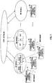
- FIG.1 is a drawing showing an example of the overall configuration of a network according to Embodiment 1 of the present invention.
- networks 1 through n are domain-unit networks such as LANs (Local Area Networks) or WANs (Wide Area Networks), with network 1 including a plurality of radio base stations (base station 1 and base station 2), and network 2 including a plurality of radio access points (AP1 and AP2), for example. That is to say, each of networks 1 through n corresponds to, for example, a public mobile phone network, private premises radio LAN, hot spot, home radio network, or the like, and is here assumed to be an IP-based network.
- These individual domain networks are connected to a core network typified by the Internet.
- Communication terminal apparatuses 10 through 30 perform video or voice communication on a one-to-one or one-to-many basis. If, for example, communication terminal apparatus 10 moves and changes from a state in which it receives radio waves from base station 1 to a state in which it receives radio waves from base station 2, handover is performed between the base stations, and communication terminal apparatus 10 can continue to perform its pre-movement communication after the movement without interruption. The same applies to the case of movement from the connection range of AP1 to the connection range of AP2.
- network layer handover (handover via the networks) is performed, and communication can be maintained. That is to say, if, for example, communication terminal apparatus 20 moves and changes from a state in which its is connected to base station 2 to a state in which its is connected to API, communication processing can be continued regardless of the fact that communication terminal apparatus 20 has moved to a different network (here, from network 1 to network 2) .
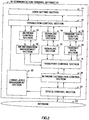
- FIG.2 is a block diagram showing the internal configuration of communication terminal apparatus 10 according to Embodiment 1 of the present invention.
- Communication terminal apparatus 10 may be a mobile telephone apparatus, or may be a PDA or personal computer with a function for connection to a radio network.
- Communication terminal apparatuses 20 and 30 are also assumed to have the same kind of configuration as communication terminal apparatus 10.
- communication terminal apparatus 10 has a hierarchical configuration, comprising connection control systems 12 through 18 above the transport layer, a transport control section 19 that performs transport layer processing, and data transmission control systems 20 and 21 below the transport layer. Also, in this embodiment, a lower layer management section 22 is newly provided to enable information relating to communication conditions of a layer lower than the transport layer of the communication terminal apparatus to be conveyed directly to a layer higher than the transport layer.
- connection control sections 12 include a connection control section 12, a network control section 13, a signaling control section 14, and a transmit data control section 15.
- Connection control section 12 is included in an application program, or used by an application program, and has a function of receiving a service request from a user and converting the service definition information to a format that can be interpreted and executed by network control section 13, signaling control section 14, and transmit data control section 15 (hereinafter referred to collectively as “control sections").
- control sections 13 through 15 check the service conditions and software execution environment controlled by connection control section 12, and issue service execution directives to NW (network) information management section 16, signaling section 17, and transmit data section 18 as necessary.
- NW network information management section
- Transport control section 19 and lower-level data transmission control systems comprising network distribution controlsection20 (performing network layer processing) and device control section 21 (performing radio device control - that is, physical layer and data link layer processing), transmit and receive data created by the high-level connection control systems to/from a network 23, and implement the service desired by the user.
- Device control section 21 can handle radio modulation schemes used in a plurality of networks in which communication terminal apparatus 10 can perform data transmission/reception.
- Network distribution control section 20 supports mobile IP (stipulated in RFC2002 of the Internet Engineering Task Force (IETF)), for example, whereby communication terminal apparatus 10 is able to carry out data transmission and reception in a plurality of different kinds of networks.
- IETF Internet Engineering Task Force
- the individual sections of communication terminal apparatus 10 may be implemented by means of hardware or software, or a combination thereof.
- Lower layer management section 22 uses a database to manage communication environment conditions detected by device control section 21 and network distribution control section 20 (detected by means of general-purpose signals, control information, performance monitoring, fault monitoring, and so forth) .
- Lower layer management section 22 reports various kinds of information recorded in the database to connection control section 12, which is an upper layer section. Specifically, lower layer management section 22 records, for example, information for identifying network 23 to which communication terminal apparatus 10 belongs, information on the modulation scheme used in this network 23, information relating to radio communication field intensity, and so forth, in the database, and in the event of a change in the recorded information, reports that information to connection control section 12.
- connection control section 12 is a part of an application, or is used directly by an application, through the operation of lower layer management section 22, radio device or network layer (typically Internet Protocol layer) communication conditions are reported directly to the application, and communication terminal apparatus 10 can perform optimal control of video, voice or suchlike data transmission from the application side. That is to say, connection control section 12 of an application is able to ascertain movement to a different network, radio wave conditions, transmission traffic, and so forth, and can implement various kinds of services centered on video/voice applications.
- network layer typically Internet Protocol layer
- Connection control section 12 provides a service generation environment, and has a function of enabling rapid application and service deployment. Specifically, connection control section 12 controls three kinds of functions: network centered service functions such as band control and authentication (corresponding to network control section 13), a signaling based control function that performs call connection to implement communication (corresponding to signaling control section 14), and user centered application service functions including profiling, content (video/voice), and so forth (corresponding to transmit data control section 15).
- network centered service functions such as band control and authentication (corresponding to network control section 13)
- signaling based control function that performs call connection to implement communication
- user centered application service functions including profiling, content (video/voice), and so forth (corresponding to transmit data control section 15).
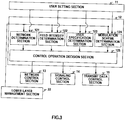
- a user setting section 11 is an input/output section whereby the user performs communication terminal apparatus settings and operations, and comprises a screen, buttons, a mouse, and so forth.
- Connection control section 12 also controls execution of commands specified by the user by means of this user setting section 11.
- connection control section 12 has a network determination section 121, a field intensity determination section 122, a user specification determination section 123, a modulation scheme determination section 124, and acontrol operation decision section 125.
- Network determination section 121 determines whether or not the network to which communication terminal apparatus 10 belongs has changed, based on information reported from lower layer management section 22. Specifically, network determination section 121 detects that a change in a prefix serving as the network identifier has been reported by lower layer management section 22, and determines that the network has changed.
- Field intensity determination section 122 determines whether or not field intensity indicating the state of radio communication has changed, based on information reported from lower layer management section 22. Specifically, field intensity determination section 122 receives notification that the field intensity recorded in the database of lower layer management section 22 has changed, and determines that the field intensity has changed.
- User specification determination section 123 determines whether or not information recorded in the database of lower layer management section 22 has been changed to a value set by user setting section 11. User specification determination section 123 monitors all the information recorded in the aforementioned database, and detects that the communication environment is in the state the user has set via user setting section 11.
- Modulation scheme determination section 124 determines whether or not the modulation scheme used by the network to which communication terminal apparatus 10 belongs has changed, based on information reported from lower layer management section 22. Specifically, modulation scheme determination section 124 receives notification that the modulation scheme recorded in the database of lower layer management section 22 has changed, and determines that the modulation scheme has changed.
- Control operation decision section 125 decides on an operation for service control in accordance with the determinations of the above-described four determination sections. That is to say, control operation decision section 125 decides on a control operation such as restricting the band for content (video/voice) transmission, or transmitting predetermined signaling information, for example, in accordance with changes in the network, field intensity, modulation scheme, and so forth. These control operations are executed by control sections 13 through 15.
- network control section 13 performs network transmission band control and authentication for a real-time application. Specifically, network control section 13 performs setting of network transmission service quality control and authentication information. Then NW information management section 16 adds information for transmitting/receiving service quality and authentication information controlled by network control section 13 to/from network 23.
- Signaling control section 14 controls the state of a call when call connection to the communicating party is performed.
- a call in this case denotes a session set up by the session layer (the layer above the transport layer) or by higher layers.
- signaling section 17 Based on the call state controlled by signaling control section 14, signaling section 17 then creates information used in call connection when there us a call connection request (far-end address, port number, and so forth), and adds information for transmitting/receiving data for establishing or clearing a call to a communicating party to/from network 23.
- Transmit data control section 15 performs creation and control of data used in real-time communication, such as video and voice data.
- the created data is coded/decoded data.
- transmit data section 18 adds information for transmitting/receiving the video, voice, or other data created by transmit data control section 15 to/from network 23.
- transport control section 19 Before data created in an upper layer is sent to network distribution control section 20, transport control section 19 links each data to a corresponding higher-level function (NW information management section 16, signaling section 17, or transmit data section 18), and when data received by a lower layer is accepted from network distribution control section 20, transport control section 19 distributes that data to the appropriate higher-level function.
- NW information management section 16, signaling section 17, or transmit data section 18 When data received by a lower layer is accepted from network distribution control section 20, transport control section 19 distributes that data to the appropriate higher-level function.
- Network distribution control section 20 sets address information and so forth necessary for transmitting data to network 23, and transmits/receives created data to/from network 23 via device control section 21.
- Device control section 21 controls a radio device (radio) necessary for performing radio communication.
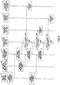
- FIG.4 is a sequence diagram exemplifying the relationship of the operations of the various sections of communication terminal apparatus 10
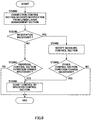
- FIG.5 is a flowchart showing the processing procedure of communication terminal apparatus 10.
- Communication terminal apparatus 10 is assumed to perform data communication for video, voice, and suchlike communications via radio access points and radio base stations.
- the connection mode may be a one-to-one mode or a communication mode such as a multipoint conference involving multiple persons.
- the user of communication terminal apparatus 10 can move around freely, making use of the advantages of radio.
- whether or not the radio environment has changed is monitored and determined constantly by device control section 21 (ST1000), and if device control section 21 detects that the radio field intensity has weakened during movement, for example, the value of the field intensity after the change (or the level value if the field intensity is indicated by a plurality of levels) is reported to lower layer management section 22 (ST1200) .
- Lower layer management section 22 writes the reported value in the field intensity location in its management database (ST1300) .
- Device control section 21 not only informs lower layer management section 22 of a change in the field intensity, but also determines whether or not the state of the radio link (link connected state (UP) or disconnected state (DOWN)) has changed, and informs lower layer management section 22 if a change is detected (ST1200) . Lower layer management section 22 then writes the reported change in the relevant location in its management database (ST1300).
- UP link connected state
- DOWN disconnected state
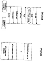
- Device control section 21 may also inform lower layer management section 22 each time the modulation scheme (type of radio signal method) changes, and/or each time the radio access point congestion state changes, and write to the location of the changed item in the management database. Not only changes in the radio access point congestion state (the number of terminals currently using that radio access point), but also changes in the radio base station congestion state may be managed. These items of information are classified as device control information in the management database of lower layer management section 22 as shown in FIG 6A , for example.
- FIG 6A shows an example of items stored in the management database of lower layer management section 22 and the value of each item.
- network distribution control section 20 detects changes in the network environment (ST1100) . If, for instance, network distribution control section 20 detects a change in the network prefix (comprising predetermined high-order bits of the IP address, for example, and serving as a network identifier (ID)), network distribution control section 20 reports the prefix value (network ID) after the change to lower layer management section 22 (ST1200). Lower layer management section 22 then writes the reported value in the prefix location in its management database (ST1300).
- a change in the network prefix comprising predetermined high-order bits of the IP address, for example, and serving as a network identifier (ID)
- network distribution control section 20 reports the prefix value (network ID) after the change to lower layer management section 22 (ST1200).
- Lower layer management section 22 then writes the reported value in the prefix location in its management database (ST1300).
- Network distribution control section 20 may also similarly inform lower layer management section 22 not only in the event of a change in the prefix, but also when the receive buffer size or the number of retransmissions changes, and write to the location of the changed item in the management database.
- the receive buffer size is a parameter that determines the amount of data sent from the communicating party that is temporarily stored in the terminal.
- the data transmitting side continuously transmits an amount of data that fills this receive buffer, and the data receiving side notifies the transmitting side of the end of reception when this receive buffer is full.
- An optimal value is selected for this receive buffer size according to the state of the network so that exchanges between the transmitting side and receiving side are not excessive, and the loss is not too great if part of the data cannot be received.
- the number of retransmissions is a value obtained by counting the number of times the same data has been retransmitted by the transmitting side when the receiving side sends the transmitting side the number of a packet that has been lost during transmission and not received, and the transmitting side resends the packet indicated by that number.
- Lower layer management section 22 constantly monitors whether or not a newly reported value has been written to the management database. Each time there is a write to the management database, the change indicated by the write is reported to connection control section 12 of the application (ST1400) . The information reported here is assumed to be only information on the changed item when there are a plurality of items in the management database. These series of operations (from detection of a radio environment change to database management, and from detection of a network environment change to database management) are carried out simultaneously and in parallel in the various sections, as shown in FIG.4 .
- Connection control section 12 performs application control based on the reported information. Since the degree of change of a particular radio environment or network environment item that should cause application control to be changed differs according to the type of application or the wishes of the user, lower layer management section 22 automatically performs a write to the management database and notification of connection control section 12 when an item changes, and whether or not application control should be changed in accordance with that change is determined on the application side - that is, by connection control section 12 (ST1500).
- a change of application control is performed by a change item being determined by network determination section 121, field intensity determination section 122, user specification determination section 123, or modulation scheme determination section 124, and service definition information or the like conveyed to transmit data control section 15 being changed by control operation decision section 125.
- information of the format shown in FIG 6B is reported from control operation decision section 125 to control sections 13 through 15.
- connection control section 12 when, for example, connection control section 12 is informed from lower layer management section 22 that the radio field intensity has changed from level 2 to level 5 (communication conditions have improved), it is determined by field intensity determination section 122 that the field intensity has changed, and as a result of this determination, it is determined by control operation decision section 125 that a change is necessary to improve the image quality and/or sound quality in video/voice communication currently in progress.
- Information relating to transmit data control shown in FIG 6B is then reported to transmit data control section 15 involved in this change (in this information, the video/voice coding parameter has a value that enables better video/voice to be obtained).
- the video/voice coding parameter is a parameter used in coding processing and decoding processing
- the transmission/reception format is basic information necessary for transmitting video/voice data to the network.
- control operation decision section 125 may also determine that control for changing the image quality and/or sound quality is necessary when the radio field intensity level value improves by 2 or more, for example.
- a change policy may be established by the application, may be built into communication terminal apparatus 10 in advance, or may be set by the user via user setting section 11. According to the change policy in this example, control operation decision section 125 does not change application control even if a change in the radio field intensity from level 2 to level 3 is reported by field intensity determination section 122.
- transmit data control section 15 begins transmit data section 18 control using this new control information (ST1600) .
- connection control section 12 when, for example, connection control section 12 is informed from lower layer management section 22 that the network prefix has changed from ID3 to ID4 due to movement of communication terminal apparatus 10, it is determined by network determination section 121 that the network has changed, and as a result of this determination, it is determined by control operation decision section 125 whether or not a change from current data communication is necessary. That is to say, if, for example, the prefix value means that a move has been made to a network with a narrower band than the network prior to the move, control operation decision section 125 determines that it is necessary to change the bandwidth to be reserved. In this case, control operation decision section 125 may store in advance network band widths corresponding to prefix values.
- the change policy as to the degree of band change for which band reservation should be changed may be established by the application, may be built into communication terminal apparatus 10 in advance, or may be set by the user via user setting section 11.
- control operation decision section 125 determines that a change is necessary, information relating to network control shown in FIG 6B is reported to network control section 13 involved in this change (in this information, the bandwidth is narrower) .
- the authentication ID is an authentication number necessary for a network move
- bandwidth is the bandwidth that optimizes data transmission.
- network control section 13 controls NW information management section 16 using this new control information so that the current bandwidth setting is changed to the new value, and implements a bandwidth reservation change corresponding to the network.
- connection control section 12 when, for example, connection control section 12 is informed from lower layer management section 22 that the radio link state has changed from UP to DOWN, it is determined by user specification determination section 123 that a change specified by the user has occurred, and as a result of this determination, it is determined by control operation decision section 125 whether or not a change from current data communication is necessary. That is to say, if, for example, upon continuing video/voice communication, a higher-level session layer call is cleared each time the radio link is cut, and it is inconvenient to set up a call again each time the radio link is connected, control is changed so that the session layer call is maintained for a predetermined time after the radio link changes from UP to DOWN. In this case, how long a session is to be maintained after the radio link is cut may be established by the application, may be built into communication terminal apparatus 10 in advance, or may be set by the user via user setting section 11.
- control operation decision section 125 determines that a change is necessary, information relating to signaling control shown in FIG 6B is reported to signaling control section 14 involved in this change. By this means, signaling section 17 is controlled so that the specified session is maintained for the specified time.
- control operation decision section 125 Depending on the kind of change determined to be necessary by control operation decision section 125, notification may be given to a plurality of control sections. For example, if it is necessary to exchange information that decides the type of video/voice or utilization parameters with the communicating party, control operation decision section 125 performs message exchange with the communicating party via signaling section 17 by notifying signaling control section 14 of the connection destination IP address, port number, and session number, together with the new video/voice type and utilization parameters as body information. Control operation decision section 125 also notifies transmit data control section 15 of the new coding parameters and transmission/reception format established by this message exchange.
- communication terminal apparatus 10 when communication terminal apparatus 10 performs data communication by means of an application that employs radio communication, reporting radio environment changes or network environment changes to the application as soon as they are detected enables the application to learn directly of lower layer information that it was not previously able to ascertain, and makes it possible to use that information to provide various seamless services matching user needs.
- Cases (1) through (8) below give specific examples of the use of communication terminal apparatus 10 according to this embodiment when performing video communication using an MPEG-4 coding scheme suitable for narrow-band moving image communication called FGS (Fine Granularity Scalability), which offers excellent adaptability to band variations.
- FGS Full Granularity Scalability
- MPEG-4 FGS which is specified in the ISO/IEC 14496-2 Amendment 4 Streaming Video Profile, allows smooth image quality adaptation to stepless transmission bands.
- An FGS moving image is composed of Base Layers and Enhancement Layers, as shown in FIG. 7 .
- the base layers (layers 0 and 4) are generated by ordinary MPEG-4 coding, and provide minimal quality.
- the enhancement layers (layers 1 through 3 and 5 through 7) are obtained by executing discrete cosine transformation, bit plane transformation, and bit plane variable-length coding on the difference between the source image and the image reconstructed from the base layer, and higher-quality moving images are provided by decoding these layers together with the base layers.
- layers 0 through 3 are an IVOP (Intra Video Object Plane) coded with only information within a frame
- layers 4 through 7 are a PVOP (Predicted Video Object Plane) prediction-coded using other frame information as well.
- a feature of this FGS image is that the image can be coded and transmitted divided into layers, and each layer can be freely selected and played back (decoded) inside the receiving-side terminal.
- Communication terminal apparatus 10 can decide which layers to code (transmit) and which layers to receive (decode) according to the communication conditions.
- an FGS moving image stream is assumed to be multicast-transmitted divided into eight separate layers.
- the receiving side can selectively receive and decode only the layers wanted by the terminal.
- network distribution control section 20 On detecting a change in the number of retransmissions, network distribution control section 20 writes the changed current value of 3 to the management database of lower layer management section 22 as the number of retransmissions . Triggered by the change in the number of retransmissions in the management database from 0 to 3, lower layer management section 22 reports "Number of retransmissions 3" to the application's connection control section 12.
- connection control section 12 When “Number of retransmissions 3" is reported to connection control section 12, the fact that the number of retransmissions has changed is detected by network determination section 121, and based on the reported "Number of retransmissions 3" control operation decision section 125 determines whether or not a transmit data control section 15 change is necessary.
- a transmit data control section 15 change In this example, as a point at which a change is necessary and the change method for that point, it is determined to be necessary to change to video transmission in which image quality is lowered and priority is given to motion by halting coding of layers 5 through 7 when the number of retransmissions increases to 3 or more. This point and the selection of layers to be transmitted are not uniquely fixed, and can be changed freely by the user by means of user setting section 11.
- control operation decision section 125 determines that a change in the layers transmitted is necessary, and reports the video/voice coding parameter value within the report information format for transmit data control section 15 (see FIG 6B ) as "Layers 0 through 4.”
- transmit data control section 15 informs transmit data section 18 that coding control is to be changed from transmission of full-quality layers 0 through 7 to halting of transmission of layers 5 through 7, and starts coding and transmission of layers 0 through 4.
- the number of retransmissions may differ according to the far-end terminal.
- transmission may be performed with all of layers 0 through 7 coded, for example, as appropriate for the far-end terminal with the smallest number of retransmissions, and with some layers selected from the coded layers for far-end terminals with a larger number of retransmissions for which the amount of data should be reduced.
- control operation decision section 125 may determine that it is not necessary to carry out a change that will lower image quality.
- control operation decision section 125 may determine that it is not necessary to carry out a change that will lower image quality if the radio field intensity has fallen to a predetermined level or below but the access point congestion state has not deteriorated. It is desirable for precise criteria of this kind to be settable and modifiable via user setting section 11 in order to reflect the user's wishes.
- the descriptions are based on MPEG-4 FGS, which allows control of the amount of data coded and transmitted on the transmitting side, and control of the amount of data received and decoded on the receiving-side, to be performed independently, but other video/voice coding schemes may of course also be used.
- MPEG-4 FGS allows control of the amount of data coded and transmitted on the transmitting side, and control of the amount of data received and decoded on the receiving-side, to be performed independently, but other video/voice coding schemes may of course also be used.
- the transmitting side when the transmitting side detects that the network band has narrowed, or detects that speed is constrained by an increase in the number of users, it can switch to a coding scheme that lowers image quality and/or sound quality and reduces the amount of data sent to the communicating party.
- transmitting-side communication conditions can be detected by the transmitting-side communication terminal apparatus, enabling control changes to be made within the transmitting-side communication terminal apparatus (although, in the case of a change of coding scheme, the change may be made after an exchange of messages with the receiving side), but receiving-side communication conditions cannot be detected directly by the transmitting-side communication terminal apparatus.
- the receiving-side communication terminal apparatus detects a change in the receiving-side radio environment or network environment, it changes the transmitting-side coding scheme by sending a signaling message to the transmitting-side communication terminal apparatus.
- This signaling message may include information concerning the coding scheme after a change (whether or not a change of coding scheme is necessary being determined by the receiving-side communication terminal apparatus based on a change in the receiving-side communication conditions), or may include information directly indicating the receiving-side communication conditions (whether or not a change of coding scheme is necessary being determined by the transmitting-side communication terminal apparatus based on a change in the receiving-side communication conditions).
- control operation decision section 125 determines whether or not it is necessary to change application control each time a radio environment or network environment item changes, but it is also possible to have this determination made by the user. That is to say, when, for example, it is detected that the radio field intensity has deteriorated, control operation decision section 125 asks the user via user setting section 11 whether or not control of control sections 13 through 15 is to be changed (and may also have the user select the kind of change to be made), and changes control in accordance with the user's instructions.
- points about which the user is to be asked can be set beforehand in control operation decision section 125 (these settings can also be made via user setting section 11) instead of asking the user about all changes, and for transmit output signal 25 to perform determination concerning communication condition changes not covered by these set points.
- control operation decision section 125 performs determination, the criteria can still be set by the user via user setting section 11.
- Set criteria can also easily be changed via user setting section 11. For example, if a user setting made when an application is started up stipulates that a change is to be made from video stream full-quality (layer 0 through 7) reception to selection and reception of layers 0 through 4 only when the field intensity changes from level 5 to level 3 (with no change being made for other radio environment changes), when "Field intensity level 3" is reported from lower layer management section 22 to device control section 21, whether or not the condition set by the user at the time of startup has been matched is determined by user specification determination section 123. In this example only one condition is set for making a change, but a plurality of conditions may be set simultaneously.
- connection control section 12 determines that it is necessary to change the service generation environment of an application based on information reported from lower layer management section 22, the change is carried out within that terminal.
- Embodiment 2 on the other hand, a case will be described in which negotiation is conducted with the communicating party.
- the local terminal may request the agreement of the far-end terminal concerning a change proposed by the local terminal in order for the agreed-to change to be executed by the local terminal, or in order for a change proposed by the local terminal to be executed by the far-end terminal, or in order for the conditions of the local terminal to be reported to the far-end terminal and to have the far-end terminal propose a change.
- connection control section 12 is the only point of difference from Embodiment 1.
- FIG.8 is a block diagram showing the detailed configuration of connection control section 12 according to Embodiment 2. Parts in FIG.8 identical to those in FIG.3 are assigned the same codes as in FIG.3 and descriptions thereof are omitted. As shown in FIG. 8 , this embodiment differs from Embodiment 1 in that control operation decision section 125 in connection control section 12 includes a signaling notification section 125a.
- signaling notification section 125a When negation with the communicating party becomes necessary as a result of determination by any of the four determination sections 121 through 124, signaling notification section 125a notifies signaling control section 14 that updating of a call involving the communication terminal is to be started.
- a communication terminal apparatus operates in the same way as in FIG. 5 up to reception by connection control section 12 of notification from lower layer management section 22. That is to say, on detecting a change in the radio environment during movement or the like, device control section 21 notifies lower layer management section 22, and lower layer management section 22 writes that change to the management database. Then, each time a change is written to the management database, the changed information is reported to connection control section 12 (ST2000). Similarly, if network distribution control section 20 detects a change in the network environment during movement or the like, the changed information is reported to connection control section 12 (ST2000).
- control operation decision section 125 determines whether or not negotiation with the communicating party is necessary based on the reported information (ST2100). For example, negotiation is necessary if a method other than the video/voice coding/decoding scheme currently being used has to be selected (such as when image disturbance occurs with the current video coding/decoding scheme due to deterioration of the radio field intensity), or if the local terminal does not have the authority to decide on an application control change.
- signaling notification section 125a in control operation decision section 125 uses the communication information format for signaling control shown in FIG 6B to notify signaling control section 14 that updating of a call involving the communicating party is to be started (ST2400).
- the information reported to signaling control section 14 includes the connection destination IP, port number, and session number, together with body information in which is written the far-end terminal, type of video/voice, and candidate information for re-determining the utilization parameters, for example.
- Signaling notification section 125a can also write information indicating lower layer communication conditions reports by lower layer management section 22 in the body information.
- signaling control section 14 On receiving this notification, signaling control section 14 changes the call status, and performs call updating via signaling section 17. Then, as a result of this signaling, it is determined by control operation decision section 125 whether or not a change in control is necessary in network control section 13 or transmit data control section 15 (ST2500), and if a change is necessary, control using the new control information is started by the relevant control section (ST2300).
- control operation decision section 125 after being notified of a lower layer information change, first determines the necessity of changing control information in control sections 13 through 15, and then determines whether or not negotiation with the communicating party is necessary in order to implement the change determined to be necessary.
- SIP Session Initiation Protocol
- SIP is text-based signaling in the application layer by means of which a session is set up between application layers.
- SIP Session Description Protocol
- RFC2327 SDP (Session Description Protocol) stipulated in RFC2327, for example, can be used as body information, and new body information can be defined and added to the header information.
- FIG.10B shows the connection sequence when communication terminal apparatuses perform MPEG4-FGS video communication (a kind of media call), for example, by means of SIP.
- the calling terminal adds SDP describing MPEG4-FGS setup to the body information, and issues an SIP message INVITE.
- the called terminal On receiving INVITE, the called terminal, when enabling communication based on the SDP contained in INVITE, transmits response 200 OK to the calling terminal. 100 Trying and 180 Ringing are provisional responses indicating that processing is in progress.
- the calling terminal On receiving 200 OK from the called terminal, the calling terminal finally returns call establishment response ACK to the called terminal, a communication session is established, and MPEG4-FGS video communication begins.
- voice and video parameters can be decided upon by means of signaling, but with a communication terminal apparatus of this embodiment, the timing for issuing signaling can be determined in accordance with communication conditions. Also, with a communication terminal apparatus of this embodiment, lower layer information of the terminal (such as the terminal's radio field intensity and currently used bandwidth) can be added as body information, and reported to connection control section 12 of the far-end terminal's application.
- lower layer information of the terminal such as the terminal's radio field intensity and currently used bandwidth
- An example of a case where negotiation is conducted with the communicating party is when the communicating party is a conventional communication terminal apparatus and does not have a lower layer management section.
- connection control section 12 of the local terminal reports the radio environment and network environment in the local terminal's network to connection control section 12, and connection control section 12 causes signaling control section 14 of the local terminal to start signaling in accordance with the flowchart in FIG.9 .
- a message provided by this signaling reaches the signaling control section of the far-end terminal, and the signaling body information is shared between connection control section 12 and the connection control section of the far-end terminal.
- This body information may be a new video/voice type or utilization parameters proposed by connection control section 12, or may be lower layer information (such as the radio field intensity received by the local terminal) reported by connection control section 12 from lower layer management section 22.
- connection control section of the far-end terminal performs a change of control information of each control section using the proposed parameters, etc., in the former case, or, in the latter case, determines whether a change of control is necessary in each control section based on the reported lower layer information.
- a lower layer management section is newly introduced that reports lower layer information to an upper layer, and the connection control section that provides an application's service generation environment recognizes lower layer information directly.
- various kinds of status determination and control changes based on lower layer information are made possible at the application level, and a video/voice communication service that the user feels to be clearly visible and audible can continue to be provided, as far as possible, even if communication conditions change in a mobile environment.
- the content distribution server (communication terminal apparatus 10) in this example monitors radio network congestion information and so forth based on information transmitted directly from a lower layer, and can perform transmission control in line with the currently used communication environment. Even in a case where a conventional type of mobile terminal with no lower layer management section receives video/voice content distribution from the content distribution server in this example, it is possible for the user to receive communication that has a more seamless feel.
- a content distribution server is installed in a fixed manner, but is provided with a radio device, and distributes video, voice, and suchlike data communications to a plurality of communication terminal apparatuses.
- the connection mode may be one-to-one distribution or 1-to-N distribution.
- device control section 21 of the content distribution server On detecting that the radio field intensity has weakened due to an increase in the number of users, for example, device control section 21 of the content distribution server writes the changed radio status to the management database of lower layer management section 22. Similarly, on detecting an increase in the number of retransmissions, a change in the receive buffer size, or the like, network distribution control section 20 writes the changed value to the management database of lower layer management section 22.
- Such a phenomenon may occur when the field intensity of a distribution destination communication terminal apparatus is poor, or in the event of severance of the radio link.
- connection control section 12 Each time there is an update in the management database, lower layer management section 22 notifies connection control section 12 of the application. On receiving this notification, control is performed in connection control section 12 to reduce the amount of data coded if the signal is weak, change to a control method that lowers video image quality and gives priority to motion (smoothness) if the number of retransmissions has increased, and so forth, in the same way as described in the various examples given above.
- a video and/or voice application requiring real-time capability is handled in a network system that includes mobile terminals whose communication conditions change from moment to moment as the terminal moves
- switching to a service adapted to a change in communication conditions can be performed more rapidly on the application side, and communication that the user feels to be more seamless can be provided in a mobile environment.
- the present invention is applicable to a communication control apparatus, communication terminal apparatus, server apparatus, and communication control method that are used in a mobile network system employing radio access points and radio base stations, and can provide users with conversational type and streaming type media services, for example.
Claims (8)
- Dispositif de contrôle de communication comprenant :une section de détection (20, 21) adaptée pour détecter au moins un d'un environnement radio, comprenant une intensité de champ de communication radio et un schéma de modulation pour une communication radio ou un environnement réseau dans une couche inférieure à une couche de transport, comprenant des informations d'identificationd'un réseau avec lequel le dispositif de contrôle de communication est associé et une condition de communication du réseau,et caractérisé par l'inclusion d'une section de gestion de couche inférieure (22) adaptée pour stocker des informations de l'environnement radio détecté ou de l'environnement réseau, et surveiller si un changement s'est ou non produit dans l'environnement radio ou dans l'environnement réseau et pour fournir un résultat de surveillance à une couche d'application, sans que le résultat ne soit acheminé via la couche de transport ; etune section de contrôle (12) adaptée pour effectuer un contrôle de service de communication dans la couche d'application, selon le résultat de surveillance reçu de la section de gestion de couche inférieure (22) sans que le résultat ne soit acheminé via la couche de transport.
- Le dispositif de contrôle de communication selon la revendication 1, dans lequel :la section de gestion de couche inférieure (22) surveille un changement dans l'environnement radio ou dans l'environnement réseau dans la couche inférieure à la couche de transport dans un modèle hiérarchique OSI (Open System Interconnection) ; etla section de contrôle (12) effectue un contrôle de service au moyen de la couche d'application selon le changement dans l'environnement dans la couche inférieure inférieure à la couche de transport.
- Le dispositif de contrôle de communication selon la revendication 2, dans lequel la section de contrôle (12) comprend
une section de décision (125) qui, lorsque le changement dans l'environnement radio ou dans l'environnement réseau satisfait à une condition prédéterminée, décide d'une opération de contrôle pour changer le service de communication selon le changement dans l'environnement radio ou dans l'environnement réseau. - Le dispositif de contrôle de communication selon la revendication 3, dans lequel la section de décision (125) change un fonctionnement relatif à au moins une d'une qualité de service dans une transmission réseau, une transmission/réception d'informations de signalisation ou une transmission/réception de données à transmettre.
- Le dispositif de contrôle de communication selon la revendication 4, dans lequel :la section de contrôle (12) comprend en outre une section de notification (125a) qui, lorsqu'une négociation avec une station communicante est nécessaire, notifie la station communicante qu'un appel impliquant la station communicante est à actualiser ; etla section de décision (125) décide d'une opération de contrôle après qu'un appel a été actualisé.
- Dispositif de terminal de communication comprenant le dispositif de contrôle de communication selon l'une des revendications 1 à 5.
- Dispositif de serveur comprenant le dispositif de contrôle de communication selon l'une des revendications 1 à 5.
- Procédé de contrôle de communication d'un dispositif de contrôle de communication, le procédé comprenant :détection d'au moins un d'un environnement radio, comprenant une intensité de champ de communication radio et un schéma de modulation pour une communication radio ou un environnement réseau dans une couche inférieure à une couche de transport, comprenant des informations d'identification d'un réseau avec lequel le dispositif de contrôle de communication est associé et une condition de communication du réseau,se caractérisant parun stockage d'informations de l'environnement radio détecté ou de l'environnement réseau, et une surveillance d'une intervention ou non d'un changement dans l'environnement radio ou dans l'environnement réseau et fourniture d'un résultat de surveillance à une couche d'application, sans que le résultat ne soit acheminé via la couche de transport ; etexécution d'un contrôle de service de communication dans la couche d'application, selon le résultat de surveillance reçu sans que le résultat ne soit acheminé via la couche de transport.
Applications Claiming Priority (3)
| Application Number | Priority Date | Filing Date | Title |
|---|---|---|---|
| JP2003021838 | 2003-01-30 | ||
| JP2003021838A JP4100182B2 (ja) | 2003-01-30 | 2003-01-30 | 通信端末装置及びその制御方法 |
| PCT/JP2004/000834 WO2004068806A1 (fr) | 2003-01-30 | 2004-01-29 | Dispositif de commande de communication, dispositif de terminal de communication, dispositif de serveur, et procede de commande de communication |
Publications (3)
| Publication Number | Publication Date |
|---|---|
| EP1580938A1 EP1580938A1 (fr) | 2005-09-28 |
| EP1580938A4 EP1580938A4 (fr) | 2015-07-15 |
| EP1580938B1 true EP1580938B1 (fr) | 2019-01-23 |
Family
ID=32820666
Family Applications (1)
| Application Number | Title | Priority Date | Filing Date |
|---|---|---|---|
| EP04706297.1A Expired - Fee Related EP1580938B1 (fr) | 2003-01-30 | 2004-01-29 | Dispositif de commande de communication, dispositif de terminal de communication, dispositif de serveur, et procédé de commande de communication |
Country Status (7)
| Country | Link |
|---|---|
| US (1) | US7634574B2 (fr) |
| EP (1) | EP1580938B1 (fr) |
| JP (1) | JP4100182B2 (fr) |
| KR (1) | KR100709971B1 (fr) |
| CN (1) | CN100496018C (fr) |
| BR (1) | BRPI0407059B1 (fr) |
| WO (1) | WO2004068806A1 (fr) |
Families Citing this family (47)
| Publication number | Priority date | Publication date | Assignee | Title |
|---|---|---|---|---|
| JP4100182B2 (ja) * | 2003-01-30 | 2008-06-11 | 松下電器産業株式会社 | 通信端末装置及びその制御方法 |
| CN1753493A (zh) * | 2004-09-24 | 2006-03-29 | 松下电器产业株式会社 | 无线多媒体通信系统的跨层联合方法 |
| US10270511B2 (en) * | 2004-11-17 | 2019-04-23 | Koninklijke Philips N.V. | Robust wireless multimedia transmission in multiple in multiple-out (MIMO) system assisted by channel state information |
| JP4454635B2 (ja) * | 2004-11-29 | 2010-04-21 | シャープ株式会社 | 帯域割り当て方法、帯域割り当てプログラム及びプログラム記録媒体 |
| US7827141B2 (en) * | 2005-03-10 | 2010-11-02 | Oracle International Corporation | Dynamically sizing buffers to optimal size in network layers when supporting data transfers related to database applications |
| US20060271658A1 (en) * | 2005-05-26 | 2006-11-30 | Cisco Technology, Inc. | Method and system for transmitting data over a network based on external non-network stimulus |
| JP4640856B2 (ja) | 2005-06-02 | 2011-03-02 | シャープ株式会社 | 通信システム及び通信端末 |
| JP2006345251A (ja) * | 2005-06-09 | 2006-12-21 | Kyocera Corp | 無線通信端末及び通信方法 |
| JP4999425B2 (ja) * | 2005-11-29 | 2012-08-15 | パナソニック株式会社 | 通信装置および通信方法 |
| US8571215B2 (en) | 2006-01-05 | 2013-10-29 | Telefonaktiebolaget L M Ericsson (Publ) | Combined storage and transmission of scalable media |
| KR100738548B1 (ko) * | 2006-01-11 | 2007-07-11 | 삼성전자주식회사 | VoIP 화상 통화 장치 및 그 방법 |
| US8244051B2 (en) * | 2006-03-15 | 2012-08-14 | Microsoft Corporation | Efficient encoding of alternative graphic sets |
| JP4779827B2 (ja) | 2006-06-29 | 2011-09-28 | 日本電気株式会社 | ネットワーク制御システム、無線通信装置、及びネットワーク制御方法 |
| KR100750189B1 (ko) * | 2006-07-04 | 2007-08-17 | 삼성전자주식회사 | 이동통신 단말기에서 화상통화 화면 공유 장치 및 방법 |
| KR100893863B1 (ko) * | 2006-09-05 | 2009-04-20 | 엘지전자 주식회사 | 무선 통신 시스템에서의 링크 적응적 데이터 전송 방법 |
| JP4806336B2 (ja) * | 2006-11-29 | 2011-11-02 | 京セラ株式会社 | 無線通信端末及び無線通信方法 |
| CN101595695B (zh) * | 2007-01-26 | 2012-11-14 | 日本电气株式会社 | 视频分发系统和视频分发方法 |
| JP2008259094A (ja) * | 2007-04-09 | 2008-10-23 | Matsushita Electric Ind Co Ltd | 無線lan電話通信方法及びシステム |
| WO2009037735A1 (fr) * | 2007-09-18 | 2009-03-26 | Fujitsu Limited | Procédé de communication, système de communication, serveur et programme pertinent pour transfert de gestion de session |
| US20100228553A1 (en) * | 2007-09-21 | 2010-09-09 | Panasonic Corporation | Communication terminal device, communication system, and communication method |
| CN101754004B (zh) * | 2008-12-16 | 2013-06-12 | 浪潮乐金数字移动通信有限公司 | 一种3g可视电话及其工作方法 |
| KR101390045B1 (ko) * | 2008-12-24 | 2014-04-30 | 에릭슨엘지엔터프라이즈 주식회사 | 통화 장치 및 그 제어 장치 |
| WO2010073671A1 (fr) | 2008-12-25 | 2010-07-01 | パナソニック株式会社 | Procédé de commande de transmission tcp et procédé de commande d'une transmission tcp |
| JP5247567B2 (ja) | 2009-04-06 | 2013-07-24 | キヤノン株式会社 | 情報処理装置及びその制御方法、並びに該制御方法をコンピュータに実行させるためのプログラム |
| CN101932034B (zh) * | 2009-06-26 | 2013-10-02 | 华为技术有限公司 | 提高服务质量的方法及系统和应用网网元 |
| WO2011001758A1 (fr) * | 2009-06-30 | 2011-01-06 | 日本電気株式会社 | Système sans fil et procédé de commutation du niveau de résolution d'images animées |
| US9538299B2 (en) | 2009-08-31 | 2017-01-03 | Hewlett-Packard Development Company, L.P. | Acoustic echo cancellation (AEC) with conferencing environment templates (CETs) |
| US20110099227A1 (en) * | 2009-10-27 | 2011-04-28 | Walls Jeffrey J | Communication application with steady-state conferencing |
| US8462797B2 (en) * | 2009-11-30 | 2013-06-11 | Alcatel Lucent | Method of priority based transmission of wireless video |
| US8713131B2 (en) * | 2010-02-23 | 2014-04-29 | RHPiscan Systems, Inc. | Simultaneous image distribution and archiving |
| JP5269850B2 (ja) * | 2010-09-17 | 2013-08-21 | 株式会社東芝 | 放送素材再生装置及びデータ送出方法 |
| CN102547266B (zh) * | 2010-12-29 | 2015-03-11 | 中国移动通信集团公司 | 一种视频数据传输方法及设备 |
| KR101744355B1 (ko) | 2011-01-19 | 2017-06-08 | 삼성전자주식회사 | 상호 계층 최적화를 이용한 멀티미디어 데이터 패킷을 송신하는 방법 및 장치 |
| CN103004281A (zh) * | 2011-03-17 | 2013-03-27 | 松下电器产业株式会社 | 控制装置、终端装置以及通信系统 |
| US8978074B2 (en) | 2011-08-29 | 2015-03-10 | At&T Mobility Ii Llc | Method and apparatus for providing wireless digital television service |
| GB2495712B (en) | 2011-10-17 | 2014-01-08 | Skype | Controlling transmission of data |
| JP2013258657A (ja) * | 2012-06-14 | 2013-12-26 | Nippon Hoso Kyokai <Nhk> | P2pネットワークサービスに用いる端末装置及びプログラム |
| JP2014003359A (ja) * | 2012-06-15 | 2014-01-09 | Samsung Electronics Co Ltd | 映像データをストリーム型データ転送するために用いられるデータ転送システム及びデータ転送システムに用いられる送信装置、受信装置及びプログラム |
| JP5642225B2 (ja) * | 2013-04-11 | 2014-12-17 | キヤノン株式会社 | 情報処理装置及びその制御方法、並びに該制御方法をコンピュータに実行させるためのプログラム |
| JP5902653B2 (ja) * | 2013-08-30 | 2016-04-13 | ソフトバンク株式会社 | 動画配信システム、動画配信装置、端末装置、及びプログラム |
| WO2015048569A2 (fr) | 2013-09-26 | 2015-04-02 | Coherent Logix, Incorporated | Système et procédé de diffusion de prochaine génération |
| CN104185235B (zh) * | 2014-08-19 | 2016-01-06 | 小米科技有限责任公司 | 无线网络调整方法及装置 |
| US9794896B2 (en) | 2014-08-19 | 2017-10-17 | Xiaomi Inc. | Method and device for adjusting state of wireless network |
| JP6582722B2 (ja) | 2015-08-19 | 2019-10-02 | ヤマハ株式会社 | コンテンツ配信装置 |
| JP2017163287A (ja) * | 2016-03-08 | 2017-09-14 | 富士ゼロックス株式会社 | 表示装置 |
| KR102421791B1 (ko) * | 2016-05-26 | 2022-07-15 | 삼성전자주식회사 | Mmt 네트워크 시스템에서 미디어 시간 정보를 전송 하는 방법 및 장치 |
| CN107395404B (zh) * | 2017-07-07 | 2018-10-30 | 腾讯科技(深圳)有限公司 | 为网络应用提示网络环境、预测服务质量的方法和装置 |
Family Cites Families (12)
| Publication number | Priority date | Publication date | Assignee | Title |
|---|---|---|---|---|
| JP2908209B2 (ja) * | 1993-11-29 | 1999-06-21 | 郵政大臣 | 移動端末装置及びこれを用いた移動体衛星通信システム |
| JPH0951571A (ja) | 1995-08-07 | 1997-02-18 | Matsushita Electric Ind Co Ltd | 移動通信装置 |
| JPH114476A (ja) | 1997-06-11 | 1999-01-06 | Nec Corp | 移動通信システム及びそのトラヒック収集制御方法並びにトラヒック収集制御プログラムを記録した記録媒体 |
| US5987033A (en) * | 1997-09-08 | 1999-11-16 | Lucent Technologies, Inc. | Wireless lan with enhanced capture provision |
| JP3236827B2 (ja) | 1999-01-18 | 2001-12-10 | 株式会社神戸製鋼所 | 無線電話装置 |
| JP2000295276A (ja) * | 1999-04-02 | 2000-10-20 | Hitachi Ltd | 通信制御システム |
| US6587479B1 (en) * | 1999-04-21 | 2003-07-01 | Opencell Corp. | Architecture for signal distribution in wireless data network |
| AU2001253740A1 (en) * | 2000-04-22 | 2001-11-07 | Atheros Communications, Inc. | Methods for controlling shared access to wireless transmission systems and increasing throughput of the same |
| US6845397B1 (en) * | 2000-12-29 | 2005-01-18 | Nortel Networks Limited | Interface method and system for accessing inner layers of a network protocol |
| JP2002344484A (ja) * | 2001-05-21 | 2002-11-29 | Nec Corp | ネットワークの接続復旧方法及びシステム |
| JP4121298B2 (ja) * | 2002-04-18 | 2008-07-23 | 松下電器産業株式会社 | 通信端末装置及び通信制御方法 |
| JP4100182B2 (ja) * | 2003-01-30 | 2008-06-11 | 松下電器産業株式会社 | 通信端末装置及びその制御方法 |
-
2003
- 2003-01-30 JP JP2003021838A patent/JP4100182B2/ja not_active Expired - Lifetime
-
2004
- 2004-01-29 EP EP04706297.1A patent/EP1580938B1/fr not_active Expired - Fee Related
- 2004-01-29 CN CNB2004800030393A patent/CN100496018C/zh not_active Expired - Fee Related
- 2004-01-29 BR BRPI0407059-3A patent/BRPI0407059B1/pt not_active IP Right Cessation
- 2004-01-29 US US10/543,176 patent/US7634574B2/en active Active
- 2004-01-29 KR KR1020057013997A patent/KR100709971B1/ko active IP Right Grant
- 2004-01-29 WO PCT/JP2004/000834 patent/WO2004068806A1/fr active Application Filing
Non-Patent Citations (1)
| Title |
|---|
| None * |
Also Published As
| Publication number | Publication date |
|---|---|
| EP1580938A1 (fr) | 2005-09-28 |
| JP2004266330A (ja) | 2004-09-24 |
| BRPI0407059B1 (pt) | 2018-01-02 |
| CN1745551A (zh) | 2006-03-08 |
| WO2004068806A1 (fr) | 2004-08-12 |
| KR100709971B1 (ko) | 2007-04-25 |
| KR20050104362A (ko) | 2005-11-02 |
| EP1580938A4 (fr) | 2015-07-15 |
| US20060253888A1 (en) | 2006-11-09 |
| CN100496018C (zh) | 2009-06-03 |
| US7634574B2 (en) | 2009-12-15 |
| JP4100182B2 (ja) | 2008-06-11 |
| BRPI0407059A (pt) | 2006-01-17 |
Similar Documents
| Publication | Publication Date | Title |
|---|---|---|
| EP1580938B1 (fr) | Dispositif de commande de communication, dispositif de terminal de communication, dispositif de serveur, et procédé de commande de communication | |
| JP4323428B2 (ja) | 異種ネットワーク間の垂直ハンドオーバにおけるQoSをサポートするシステムおよび方法 | |
| US8014381B2 (en) | Communication system and communication terminal | |
| US10034235B2 (en) | Method and apparatus for wireless communication using location based information | |
| EP1435748A1 (fr) | Transfert entre réseaux mobiles de technologies différentes | |
| US20080130563A1 (en) | Communication Terminal and Network Control Device | |
| RU2350046C2 (ru) | Способ, схема сети связи, сервер сети связи, терминал и программное средство для выбора и изменения режимов работы для голосового соединения с коммутацией пакетов | |
| WO2006075685A1 (fr) | Procede de selection de routeur, dispositif d'agent local, routeur mobile et systeme de reseau mobile | |
| CN101741741A (zh) | 一种通信方法及通信系统 | |
| Adamopoulou et al. | Intelligent access network selection in heterogeneous networks-simulation results | |
| CN102546418A (zh) | 基于重叠网络多径传输的ims客户端及媒体交换方法 | |
| CA2542015C (fr) | Systeme et procede permettant de gerer la mobilite des couches ip dans un reseau sans fil | |
| JP2003527011A (ja) | 移動通信網 | |
| KR20070072853A (ko) | 이종 환경에서의 투명한 서비스 적합화 | |
| CN100589640C (zh) | 一种传送语音呼叫连续性业务的业务状态的方法 | |
| JP4705863B2 (ja) | セッション制御システム、セッション制御方法及び移動端末装置 | |
| CN109818901A (zh) | 报文头压缩机制确定方法、设备及系统 | |
| CN100473059C (zh) | 一种切换媒体流编解码格式的方法 | |
| JP2004265154A (ja) | ヘテロジニアスネットワークにおけるセッション維持方法及びその移動ノード | |
| JP5722171B2 (ja) | 通信システム、アクセスポイント、サーバ装置および通信制御方法 | |
| JP3588570B2 (ja) | 通信フロー制御方法、通信端末、そのプログラム記録媒体 | |
| JP2000278325A (ja) | 伝送制御方法 | |
| JP4995637B2 (ja) | 通信装置および無線通信方法 | |
| US11979332B2 (en) | Adaptive networking for resilient communications | |
| JP4578414B2 (ja) | 階層符号化マルチキャスト通信システム |
Legal Events
| Date | Code | Title | Description |
|---|---|---|---|
| PUAI | Public reference made under article 153(3) epc to a published international application that has entered the european phase |
Free format text: ORIGINAL CODE: 0009012 |
|
| 17P | Request for examination filed |
Effective date: 20050715 |
|
| AK | Designated contracting states |
Kind code of ref document: A1 Designated state(s): AT BE BG CH CY CZ DE DK EE ES FI FR GB GR HU IE IT LI LU MC NL PT RO SE SI SK TR |
|
| AX | Request for extension of the european patent |
Extension state: AL LT LV MK |
|
| DAX | Request for extension of the european patent (deleted) | ||
| RBV | Designated contracting states (corrected) |
Designated state(s): DE FR GB |
|
| RIN1 | Information on inventor provided before grant (corrected) |
Inventor name: XU, MING QIANGC/O MATSUSHITA ELECTRIC INDUSTRIAL Inventor name: TAKESHITA, SACHIKO Inventor name: NAKANO, GO Inventor name: SENGA, SATOSHI |
|
| RIN1 | Information on inventor provided before grant (corrected) |
Inventor name: XU, MING QIANGMATSUSHITA ELECTRIC INDUSTRIAL Inventor name: TAKESHITA, SACHIKO Inventor name: NAKANO, GOMATSUSHITA ELECTRIC INDUSTRIAL CO.LTD. Inventor name: SENGA, SATOSHI |
|
| RAP1 | Party data changed (applicant data changed or rights of an application transferred) |
Owner name: PANASONIC CORPORATION |
|
| RAP1 | Party data changed (applicant data changed or rights of an application transferred) |
Owner name: PANASONIC INTELLECTUAL PROPERTY CORPORATION OF AME |
|
| RA4 | Supplementary search report drawn up and despatched (corrected) |
Effective date: 20150617 |
|
| RIC1 | Information provided on ipc code assigned before grant |
Ipc: H04L 12/801 20130101ALI20150611BHEP Ipc: H04L 12/859 20130101AFI20150611BHEP Ipc: H04W 24/00 20090101ALI20150611BHEP |
|
| STAA | Information on the status of an ep patent application or granted ep patent |
Free format text: STATUS: EXAMINATION IS IN PROGRESS |
|
| 17Q | First examination report despatched |
Effective date: 20170303 |
|
| GRAP | Despatch of communication of intention to grant a patent |
Free format text: ORIGINAL CODE: EPIDOSNIGR1 |
|
| STAA | Information on the status of an ep patent application or granted ep patent |
Free format text: STATUS: GRANT OF PATENT IS INTENDED |
|
| INTG | Intention to grant announced |
Effective date: 20181002 |
|
| GRAS | Grant fee paid |
Free format text: ORIGINAL CODE: EPIDOSNIGR3 |
|
| GRAA | (expected) grant |
Free format text: ORIGINAL CODE: 0009210 |
|
| STAA | Information on the status of an ep patent application or granted ep patent |
Free format text: STATUS: THE PATENT HAS BEEN GRANTED |
|
| AK | Designated contracting states |
Kind code of ref document: B1 Designated state(s): DE FR GB |
|
| REG | Reference to a national code |
Ref country code: GB Ref legal event code: FG4D |
|
| REG | Reference to a national code |
Ref country code: DE Ref legal event code: R096 Ref document number: 602004053656 Country of ref document: DE |
|
| REG | Reference to a national code |
Ref country code: DE Ref legal event code: R097 Ref document number: 602004053656 Country of ref document: DE |
|
| PLBE | No opposition filed within time limit |
Free format text: ORIGINAL CODE: 0009261 |
|
| STAA | Information on the status of an ep patent application or granted ep patent |
Free format text: STATUS: NO OPPOSITION FILED WITHIN TIME LIMIT |
|
| GBPC | Gb: european patent ceased through non-payment of renewal fee |
Effective date: 20190423 |
|
| 26N | No opposition filed |
Effective date: 20191024 |
|
| PG25 | Lapsed in a contracting state [announced via postgrant information from national office to epo] |
Ref country code: GB Free format text: LAPSE BECAUSE OF NON-PAYMENT OF DUE FEES Effective date: 20190423 |
|
| PG25 | Lapsed in a contracting state [announced via postgrant information from national office to epo] |
Ref country code: FR Free format text: LAPSE BECAUSE OF NON-PAYMENT OF DUE FEES Effective date: 20190323 |
|
| REG | Reference to a national code |
Ref country code: DE Ref legal event code: R079 Ref document number: 602004053656 Country of ref document: DE Free format text: PREVIOUS MAIN CLASS: H04L0012859000 Ipc: H04L0047247500 |
|
| PGFP | Annual fee paid to national office [announced via postgrant information from national office to epo] |
Ref country code: DE Payment date: 20220119 Year of fee payment: 19 |
|
| REG | Reference to a national code |
Ref country code: DE Ref legal event code: R119 Ref document number: 602004053656 Country of ref document: DE |
|
| PG25 | Lapsed in a contracting state [announced via postgrant information from national office to epo] |
Ref country code: DE Free format text: LAPSE BECAUSE OF NON-PAYMENT OF DUE FEES Effective date: 20230801 |