EP1580490B1 - Verkleidungsplatte für die Frontseite eines Heizkörpers sowie Verfahren zur Herstellung der Verkleidungsplatte - Google Patents
Verkleidungsplatte für die Frontseite eines Heizkörpers sowie Verfahren zur Herstellung der Verkleidungsplatte Download PDFInfo
- Publication number
- EP1580490B1 EP1580490B1 EP05006114A EP05006114A EP1580490B1 EP 1580490 B1 EP1580490 B1 EP 1580490B1 EP 05006114 A EP05006114 A EP 05006114A EP 05006114 A EP05006114 A EP 05006114A EP 1580490 B1 EP1580490 B1 EP 1580490B1
- Authority
- EP
- European Patent Office
- Prior art keywords
- cladding panel
- edges
- chamfer
- radius
- panel
- Prior art date
- Legal status (The legal status is an assumption and is not a legal conclusion. Google has not performed a legal analysis and makes no representation as to the accuracy of the status listed.)
- Expired - Lifetime
Links
- 238000000034 method Methods 0.000 title claims description 5
- 238000005253 cladding Methods 0.000 claims abstract description 136
- 238000005452 bending Methods 0.000 claims abstract description 32
- 239000000463 material Substances 0.000 claims abstract description 24
- 238000007493 shaping process Methods 0.000 claims description 13
- 238000004519 manufacturing process Methods 0.000 claims description 11
- 238000012545 processing Methods 0.000 claims description 8
- 230000007704 transition Effects 0.000 description 10
- 210000002105 tongue Anatomy 0.000 description 6
- 230000015572 biosynthetic process Effects 0.000 description 3
- 230000006378 damage Effects 0.000 description 3
- 229920001817 Agar Polymers 0.000 description 2
- 208000027418 Wounds and injury Diseases 0.000 description 2
- 238000005520 cutting process Methods 0.000 description 2
- 230000002349 favourable effect Effects 0.000 description 2
- 208000014674 injury Diseases 0.000 description 2
- 238000010008 shearing Methods 0.000 description 2
- 238000004026 adhesive bonding Methods 0.000 description 1
- 238000007688 edging Methods 0.000 description 1
- 230000001747 exhibiting effect Effects 0.000 description 1
- 238000007689 inspection Methods 0.000 description 1
- 239000002184 metal Substances 0.000 description 1
- 230000000116 mitigating effect Effects 0.000 description 1
- 238000012805 post-processing Methods 0.000 description 1
- 238000002360 preparation method Methods 0.000 description 1
- 238000004080 punching Methods 0.000 description 1
- 238000003856 thermoforming Methods 0.000 description 1
- 230000009466 transformation Effects 0.000 description 1
- 238000009966 trimming Methods 0.000 description 1
Images

Classifications
-
- F—MECHANICAL ENGINEERING; LIGHTING; HEATING; WEAPONS; BLASTING
- F24—HEATING; RANGES; VENTILATING
- F24D—DOMESTIC- OR SPACE-HEATING SYSTEMS, e.g. CENTRAL HEATING SYSTEMS; DOMESTIC HOT-WATER SUPPLY SYSTEMS; ELEMENTS OR COMPONENTS THEREFOR
- F24D19/00—Details
- F24D19/06—Casings, cover lids or ornamental panels, for radiators
Definitions
- the invention relates to a cladding panel for the front of a radiator, in particular a panel radiator, according to claim 1 and a method for producing such a cladding panel according to claim 12.
- Radiators and in particular panel radiators are usually clad by additional components in the outer area of the radiator and thereby made visually pleasing. If the largest possible surface for the heat exchange with the air flowing through is desired for the interior of a radiator, the outer surfaces of the radiator should be as smooth as possible and thus visually pleasing and simply kept clean. Therefore, both on the top of panel radiators as well as on the sides and increasingly in the front of the panel radiator corresponding covers and panels are provided, which are attached to the actual radiator and meet the criteria mentioned above. The cladding of the front of a panel radiator is becoming increasingly important.
- cladding panels formed from sheets on the front of the panel heater by gluing or by releasable connections, which have the dimensions of the panel radiator substantially and extend up to the arranged in the region of the top and sides of the panel radiator covering parts.
- the front cladding panels should be both visually pleasing and mitigating designed with respect to protruding edges, sharp corners or the like, so that about the plate radiator passing or handling these people can not be injured or otherwise damaged. Therefore, such cladding panels are designed so that the cladding panels are rounded in the open area, in particular, the corners are rounded.
- Such a cladding panel is for example also from the EP 0703415 B1 known.
- a rounded corner at the four corners of the cladding plate is formed by the fact that at least two tongues are formed in the region of the corner of the blank of the cladding plate, which are bent to form a rounding corresponding to the edges, their flanks close together or tight should come to rest against the ends of the bent edges.
- Such a trim panel takes advantage of the fact that the stiffening and also to reduce the above-mentioned problems, the edges of the trim panel usually about 180 degrees to form a relatively tight bend radius to the level of the trim panel and into the interior of the trim panel and thus in the assembled state be designed to show the panel radiator.
- the present invention seeks to provide a cladding panel generic type, which is easy to manufacture and still forms a visually pleasing and largely on the outside of the panel radiator optically closed design of the cladding panel in the corner.
- a cladding panel for the front of a radiator in particular a panel radiator, is proposed, whose edges are bent with a tight bending radius by about 180 ° on one side of the cladding panel and having a corner connecting the edges rounding.
- such a generic cladding panel is further developed in that the flat blank of the cladding panel has at least at one corner substantially arranged at an angle chamfer and / or an arcuately curved course, the corner region bounding edges after bending on one side Covering plate spaced from each other to come to rest and the material of the blank on the chamfer and / or the arcuate curve in the space between the edges is also deformed so far to this side of the cladding panel that in this distance range substantially to the apex of the bending radius extending and substantially perpendicular to the plane of the cladding panel jetgekanteter boundary wall forms.
- the basic idea of the proposed cladding panel is it, in the corner between to make the bent edges of the cladding panel no real bending of the material of the flat blank, which runs similar to the bending of the edges of the cladding panel, but as in a deep-drawing of flat cups only the outer area of the corner between the end portions of the edges of the cladding panel as high to make that, based on the position of use of the cladding panel on the panel radiator, results in a substantially optically closed configuration of the corner.
- this corner must not necessarily be completely bent as the edges around 180 degrees to the plane of the cladding panel around, but must only be folded so far that can be visually reach a rounded corner. This can be achieved even with a fold of 90 ° or a little more.
- the outer edge of the material of the blank does not have to be trimmed cautiously beforehand and then individual sections such as the tongues or tabs of an otherwise necessary special blank are elaborately bent and applied to the adjacent areas of the edges of the trim panel, but it is by deformation of this Range only up to the extent that the material superscript by a thermoforming similar deformation that approximately up to the apex of the bending radius results in the navalgekantete boundary wall.
- This boundary wall thus visually laminated only the corner portion of the cladding panel to the outside, without producing an actual end of the gap between the edges on the inside of the cladding panel or even try.
- This little deformation of the material for the boundary wall can be made in the same work operation as the bending of the edges of the cladding panel, possibly a little post-processing for smooth application of the Begrenzungswall to the desired contour of the rounding of the cladding panel is necessary. This is because when bending the edges in the area of the chamfer locally the material of the cladding panel bulges slightly outward and therefore this bulge must be corrected again in further deformation of the boundary wall.
- the chamfer of the flat blank of the cladding panel is arranged at an angle of substantially 45 ° to the adjacent edges of the blank. Such a shape is particularly easy to produce about when cutting the sheets and requires little effort and thus low costs. It is conceivable that instead of a simple chamfer, the basic shape of a chamfer is combined with radii provided transition areas or sections to adjust the boundary wall after shaping to an optimal height relative to the level of the cladding panel and on a visually favorable design. It is conceivable in another embodiment that the chamfer of the flat blank of the cladding panel has an edge dimension of about 15 mm. Depending on the size of the rounding to be produced in the corner region of the cladding panel, this measure must be adjusted accordingly.
- the arcuately curved course of the flat blank of the cladding panel has a substantially circular radius.
- more material for producing the Begrenzungswalls is provided there just in the distance region relative to the training as a straight chamfer, where this material is needed to achieve a favorable height of the Begrenzungswalls.
- the size of the radius and the location of the radius relative to the edges of the material available for forming the Begrenzungswalls available material can be varied accordingly.
- a particularly advantageous embodiment can be achieved in that the circular radius has a radius of about 100 mm and merges in a further embodiment substantially tangentially in the edges of the blank.
- the invention further relates to a method for producing a cladding panel for the front of a radiator, in particular a cladding panel according to claim 1.
- a chamfer is attached to at least one corner region of the blank of the cladding panel, the edges of the blank adjacent the chamfer Angle of less than substantially 180 ° to one side of the cladding plate to form a tight radius are bent and formed in the corner of the cladding panel by forming a rounding, after which in a further processing step, the end position of the edges by bending to an angle of substantially 180 ° based adjusted to the level of the cladding panel.
- the two-stage shaping of the edges by a first bending by an angle of less than 180 degrees makes it possible to perform the deformation in the region of the Begrenzungswalls and position the not yet completed cladding panel and fix so that the deformation of the Begrenzungswall can be made as intended , Only after the boundary wall has been manufactured as intended is then carried out in the area of the edges, the final bending of the edges to 180 degrees with respect to the plane of the cladding panel and additionally once again material in the boundary wall, which may have set up beyond the desired level , pressed flat again.
- a corner forms, which has no sharp edges and therefore no cause for accidents or injuries or damage.
- the pre-bent corner region of the cladding panel can only assume the initial position necessary for the transformation and a correspondingly designed forming tool bring about the formation of the boundary wall.
- a recessed rounded forming die which is approximately perpendicular to the plane of the cladding panel to proceed to the corner and the corner area, forming the rounding with its depression, absorbs and transforms.
- This forming die can also carry out several corresponding forming operations, with which the material of the Begrenzungswalls is gradually brought into the desired shape gradually.
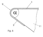
- a cladding panel 1 according to the invention is shown in various stages of processing, wherein in the FIGS. 1 a and 1 b respectively different embodiments of the blank, in the FIGS. 2 and 3 a first processing state after the partial bending of the edges 2, in the FIG. 4 a processing status after the production of the Begrenzungswall 8 in the region of the rounding 9 and in the FIG. 5 the finished processing status of the cladding panel 1 with flattened edges 2 is shown.
- FIG. 6 is then a receptacle for the positioning and clamping of a cladding panel 1 according to the invention in the manufacture of the Begrenzungswall 8 shown.
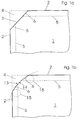
- FIG. 1 a is a blank of a cladding panel 1 to be seen from a flat material consisting approximately of sheet metal, in which a chamfer 3 is separated at an angle of about 45 degrees to the two adjacent edges 2.
- the cut portion 4 is separated from the blank of the trim panel 1 by shearing on a shearing machine or the like, for example.
- the bending of the edges 2 serves on the one hand to stiffen the cladding panel 1 and on the other to the otherwise sharply formed edges of the cladding panel 1 after bending in a configuration in the intended assembled state of the cladding panel 1 to the interior of a non-illustrated Radiator shows no one can hurt and therefore prevents injury.
- FIG. 1b another embodiment of the blank of a trim panel 1 is shown in which the chamfer 3 according to FIG. 1 a is replaced by a combination of radii 14, 15 and thus forms an arcuate curve 13.
- a large radius 14 is arranged so that it essentially the function of the chamfer 3 in accordance FIG. 1 a takes over and the cut-away material 4 separates from the material required for the formation of the boundary wall 8 of the blank 1.
- each smaller radius sections are provided as a transition end of the radius 14, which are part of a dashed radius 15 and form a smooth transition between the radius 14 and the edges 2.
- corner region of the blank 1 By such a design of the corner region of the blank 1 can be taken to ensure that material for shaping the Begrenzungswalls 8 is available just where the boundary wall 8 can be formed without wrinkling of the material low and yet the easy to wrinkle-prone material outside the later Begrenzungswalls 8 is minimized.
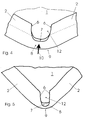
- the bending of the edges 2 in a first processing step is not the same as in generic cladding panels at an angle of 180 degrees to the plate plane of the cladding panel 1 around, but by an angle which is smaller by the angle ⁇ than 180 degrees ,
- the chamfer 3 and the bending of the edges 2 forms a substantially U-shaped cutout 12 in the area of the later to be produced rounding 9 the end portions 6 of the edges 2, which remains in its deepest region 7 continues at the height of the plane of the cladding panel 1.
- this bending of the edges 2 as a normal folding as with a sheet of paper, wherein the opening of the U-shaped cutout 12 is formed solely by the chamfer of the chamfer 3.
- the opening of the U-shaped cutout 12 is formed solely by the chamfer of the chamfer 3.
- a recess in the form of the later desired rounding 9 exhibiting tool approximately perpendicular to the corner of the cladding panel 1 and parallel to the plane of the cladding panel 1 in the direction of the arrow marked with 10 on the corner shifted, which deforms the initially still further outward portions of the later upper edge 7 of the Begrenzungswalls 8 in the direction of the trim panel 1.
- this area along the previous chamfer 3 will raise itself to a provided with a small radius Begrenzungswalls 8, which is slightly above the plane of the cladding panel 1 to form the rounding 9.
- the tool is formed with its recess so that parallel to the edge 2 of this Begrenzungswalls also has the bending radius of the edges 2, then in the later intended mounted state of the cladding panel 1 of this boundary wall 8 ensure a visually largely complete completion of the corner region of the cladding panel 1.
- the upper edge 7 of the Begrenzungswalls 8 is made only so far up out of the plane of the cladding panel 1 out that the upper edge 7 approximately at the apex of the later bending radius of the edges 2 according to the FIG. 5 in the final state of the panel 1 comes to rest.
- the upper edge 7 of the Begrenzungswalls 8 is placed about 90 degrees or slightly more out of the plane of the cladding panel 1 upwards and thus the gap between the end portions 6 of the edges 2 only in the visible region of the intended mounted trim panel 1 essentially covers the entire surface.
- the U-shaped cutout 12 To the interior of the cladding panel 1 out remains the U-shaped cutout 12, so that no great accuracy in deforming the end portions 6 of the edges 2 is required here.
- the final state of the corner region of the cladding panel 1 is shown, wherein the edges 2 were bent by a subsequent forming about by a flat punch now about 180 degrees relative to the plane of the cladding panel 1 and thus approximately parallel to the plane of the cladding panel 1 above this level to be roughly parallel.
- the upper edge 7 of the Begrenzungswalls 8 is approximately in the plane of the top of the bent edges 2, so that when viewing the cladding panel 1 parallel to the plane of the cladding panel 1, the area of the rounding 9 is apparently completely closed by the boundary wall 8.
- FIG. 6 is schematically illustrated in a section across a portion in the region of the bent edges 2, as a cladding panel 1 according to the state in the FIG. 2 placed on a receptacle 11 and fixed there, in engages the bent by the angle ⁇ area between the plane of the cladding panel 1 and the partially bent edges 2 and against which the edges 2 can be supported. So determined on the receptacle 11, the rounding 9 can be made with the tool not shown.
Landscapes
- Engineering & Computer Science (AREA)
- Physics & Mathematics (AREA)
- Thermal Sciences (AREA)
- Chemical & Material Sciences (AREA)
- Combustion & Propulsion (AREA)
- Mechanical Engineering (AREA)
- General Engineering & Computer Science (AREA)
- Bending Of Plates, Rods, And Pipes (AREA)
- Finishing Walls (AREA)
- Shaping Of Tube Ends By Bending Or Straightening (AREA)
- Re-Forming, After-Treatment, Cutting And Transporting Of Glass Products (AREA)
Priority Applications (1)
| Application Number | Priority Date | Filing Date | Title |
|---|---|---|---|
| PL05006114T PL1580490T3 (pl) | 2004-03-23 | 2005-03-21 | Płyta okładziny dla przedniej strony grzejnika oraz sposób wytwarzania płyty okładziny |
Applications Claiming Priority (2)
| Application Number | Priority Date | Filing Date | Title |
|---|---|---|---|
| DE102004014606 | 2004-03-23 | ||
| DE102004014606A DE102004014606B3 (de) | 2004-03-23 | 2004-03-23 | Verkleidungsplatte für die Frontseite eines Heizkörpers sowie Verfahren zur Herstellung der Verkleidungsplatte |
Publications (3)
| Publication Number | Publication Date |
|---|---|
| EP1580490A2 EP1580490A2 (de) | 2005-09-28 |
| EP1580490A3 EP1580490A3 (de) | 2006-01-04 |
| EP1580490B1 true EP1580490B1 (de) | 2011-10-12 |
Family
ID=34745455
Family Applications (1)
| Application Number | Title | Priority Date | Filing Date |
|---|---|---|---|
| EP05006114A Expired - Lifetime EP1580490B1 (de) | 2004-03-23 | 2005-03-21 | Verkleidungsplatte für die Frontseite eines Heizkörpers sowie Verfahren zur Herstellung der Verkleidungsplatte |
Country Status (4)
| Country | Link |
|---|---|
| EP (1) | EP1580490B1 (pl) |
| AT (1) | ATE528593T1 (pl) |
| DE (1) | DE102004014606B3 (pl) |
| PL (1) | PL1580490T3 (pl) |
Families Citing this family (3)
| Publication number | Priority date | Publication date | Assignee | Title |
|---|---|---|---|---|
| ITPD20050026U1 (it) * | 2005-04-13 | 2006-10-14 | Tubes Radiatori Srl | Radiatore per uso riscaldamento |
| CN102954530A (zh) * | 2012-11-22 | 2013-03-06 | 无锡鸿声铝业有限公司 | 艺术散热器 |
| DE102013202058A1 (de) * | 2013-02-08 | 2014-08-14 | Caradon Stelrad B.V. | Verfahren zum Verkleiden eines Plattenheizkörpers |
Family Cites Families (3)
| Publication number | Priority date | Publication date | Assignee | Title |
|---|---|---|---|---|
| DE9415520U1 (de) * | 1994-09-24 | 1995-01-19 | Ulamo Beheer B.V., Ulft | Frontverkleidung für Plattenheizkörper |
| DE29611922U1 (de) * | 1996-07-09 | 1996-09-05 | Wiemann GmbH, 58644 Iserlohn | Verkleidungsplatte |
| DE29912593U1 (de) * | 1999-07-20 | 1999-11-04 | Ulamo Beheer B.V., Ulft | Frontpaneele |
-
2004
- 2004-03-23 DE DE102004014606A patent/DE102004014606B3/de not_active Expired - Fee Related
-
2005
- 2005-03-21 PL PL05006114T patent/PL1580490T3/pl unknown
- 2005-03-21 AT AT05006114T patent/ATE528593T1/de active
- 2005-03-21 EP EP05006114A patent/EP1580490B1/de not_active Expired - Lifetime
Also Published As
| Publication number | Publication date |
|---|---|
| EP1580490A2 (de) | 2005-09-28 |
| ATE528593T1 (de) | 2011-10-15 |
| DE102004014606B3 (de) | 2005-08-11 |
| EP1580490A3 (de) | 2006-01-04 |
| PL1580490T3 (pl) | 2012-07-31 |
Similar Documents
| Publication | Publication Date | Title |
|---|---|---|
| DE10392607T5 (de) | Verfahren und Vorrichtung zur Herstellung eines Falzes | |
| EP2841217B1 (de) | Verfahren zum biegen eines verbundblechs | |
| EP3714735B1 (de) | Schubladenseitenwand | |
| EP1580490B1 (de) | Verkleidungsplatte für die Frontseite eines Heizkörpers sowie Verfahren zur Herstellung der Verkleidungsplatte | |
| DE19741856A1 (de) | Rippe für einen Wärmeübertrager und Verfahren zur Herstellung von Rippendurchzügen in derartigen Rippen | |
| DE102007006664A1 (de) | Flachrohr für Wärmetauscher | |
| DE4442434C1 (de) | Verfahren zum Herstellen rollgeformter Hohlprofile aus Blech | |
| DE102012106420A1 (de) | Verfahren und Vorrichtung zum Biegen eines Leichtblechs | |
| DE19753653A1 (de) | Stahlblechtür | |
| DE10018093A1 (de) | Verzahnung für eine Synchronisiereinheit | |
| DE10114078A1 (de) | Wärmetauscher und Herstellungsverfahren | |
| DE20103473U1 (de) | Spülebecken | |
| EP3478426B1 (de) | Verfahren zur herstellung von zierleisten und unter verwendung des verfahrens hergestellte zierleisten | |
| DE3515329A1 (de) | Gestanzter anschlusskopf fuer ein scheibenwischerelement, verfahren zu dessen herstellung und ein diesen kopf aufweisendes scheibenwischerelement | |
| DE69301550T2 (de) | Armierung für Abdichtungsleisten und Abdichtungsleisten mit einer solchen Armierung | |
| DE10062836A1 (de) | Verfahren zur Herstellung eines rohrförmigen Hohlkörpers | |
| CH95866A (de) | Wellblech. | |
| DE102008034636A1 (de) | Herstellungsverfahren für Pressteile und zugehöriges Umformwerkzeug | |
| DE4140958A1 (de) | Wischarm, insbesondere zur reinigung von scheiben an kraftfahrzeugen | |
| DE69908732T2 (de) | Aus gefalzten Blechen bestehendes Bauteil, sowie dessen Herstellungsverfahren | |
| EP1970612A1 (de) | Eckwinkelsystem für Verbindungsflanschabschnitte von Blechkanalabschnitten | |
| DE2020702A1 (de) | Scherenartiges Werkzeug | |
| AT392026B (de) | Formteil zur herstellung von rohrfoermigen teilen mit laengsnaht und daraus hergestelltes rohr bzw. rohrstueck | |
| DE4417917C2 (de) | Lamellen-Einsatz zur Abschirmung der Lichtaustrittsöffnung von Lichtrohren | |
| DE29508974U1 (de) | Profilelement |
Legal Events
| Date | Code | Title | Description |
|---|---|---|---|
| PUAI | Public reference made under article 153(3) epc to a published international application that has entered the european phase |
Free format text: ORIGINAL CODE: 0009012 |
|
| AK | Designated contracting states |
Kind code of ref document: A2 Designated state(s): AT BE BG CH CY CZ DE DK EE ES FI FR GB GR HU IE IS IT LI LT LU MC NL PL PT RO SE SI SK TR |
|
| AX | Request for extension of the european patent |
Extension state: AL BA HR LV MK YU |
|
| PUAL | Search report despatched |
Free format text: ORIGINAL CODE: 0009013 |
|
| AK | Designated contracting states |
Kind code of ref document: A3 Designated state(s): AT BE BG CH CY CZ DE DK EE ES FI FR GB GR HU IE IS IT LI LT LU MC NL PL PT RO SE SI SK TR |
|
| AX | Request for extension of the european patent |
Extension state: AL BA HR LV MK YU |
|
| 17P | Request for examination filed |
Effective date: 20060704 |
|
| AKX | Designation fees paid |
Designated state(s): AT BE BG CH CY CZ DE DK EE ES FI FR GB GR HU IE IS IT LI LT LU MC NL PL PT RO SE SI SK TR |
|
| 17Q | First examination report despatched |
Effective date: 20090325 |
|
| GRAP | Despatch of communication of intention to grant a patent |
Free format text: ORIGINAL CODE: EPIDOSNIGR1 |
|
| GRAS | Grant fee paid |
Free format text: ORIGINAL CODE: EPIDOSNIGR3 |
|
| GRAA | (expected) grant |
Free format text: ORIGINAL CODE: 0009210 |
|
| AK | Designated contracting states |
Kind code of ref document: B1 Designated state(s): AT BE BG CH CY CZ DE DK EE ES FI FR GB GR HU IE IS IT LI LT LU MC NL PL PT RO SE SI SK TR |
|
| REG | Reference to a national code |
Ref country code: GB Ref legal event code: FG4D Free format text: NOT ENGLISH |
|
| REG | Reference to a national code |
Ref country code: CH Ref legal event code: EP |
|
| REG | Reference to a national code |
Ref country code: IE Ref legal event code: FG4D |
|
| REG | Reference to a national code |
Ref country code: DE Ref legal event code: R096 Ref document number: 502005011993 Country of ref document: DE Effective date: 20111215 |
|
| REG | Reference to a national code |
Ref country code: NL Ref legal event code: T3 |
|
| LTIE | Lt: invalidation of european patent or patent extension |
Effective date: 20111012 |
|
| PG25 | Lapsed in a contracting state [announced via postgrant information from national office to epo] |
Ref country code: LT Free format text: LAPSE BECAUSE OF FAILURE TO SUBMIT A TRANSLATION OF THE DESCRIPTION OR TO PAY THE FEE WITHIN THE PRESCRIBED TIME-LIMIT Effective date: 20111012 Ref country code: IS Free format text: LAPSE BECAUSE OF FAILURE TO SUBMIT A TRANSLATION OF THE DESCRIPTION OR TO PAY THE FEE WITHIN THE PRESCRIBED TIME-LIMIT Effective date: 20120212 |
|
| REG | Reference to a national code |
Ref country code: IE Ref legal event code: FD4D |
|
| PG25 | Lapsed in a contracting state [announced via postgrant information from national office to epo] |
Ref country code: GR Free format text: LAPSE BECAUSE OF FAILURE TO SUBMIT A TRANSLATION OF THE DESCRIPTION OR TO PAY THE FEE WITHIN THE PRESCRIBED TIME-LIMIT Effective date: 20120113 Ref country code: SI Free format text: LAPSE BECAUSE OF FAILURE TO SUBMIT A TRANSLATION OF THE DESCRIPTION OR TO PAY THE FEE WITHIN THE PRESCRIBED TIME-LIMIT Effective date: 20111012 Ref country code: SE Free format text: LAPSE BECAUSE OF FAILURE TO SUBMIT A TRANSLATION OF THE DESCRIPTION OR TO PAY THE FEE WITHIN THE PRESCRIBED TIME-LIMIT Effective date: 20111012 Ref country code: PT Free format text: LAPSE BECAUSE OF FAILURE TO SUBMIT A TRANSLATION OF THE DESCRIPTION OR TO PAY THE FEE WITHIN THE PRESCRIBED TIME-LIMIT Effective date: 20120213 |
|
| PG25 | Lapsed in a contracting state [announced via postgrant information from national office to epo] |
Ref country code: CY Free format text: LAPSE BECAUSE OF FAILURE TO SUBMIT A TRANSLATION OF THE DESCRIPTION OR TO PAY THE FEE WITHIN THE PRESCRIBED TIME-LIMIT Effective date: 20111012 |
|
| PG25 | Lapsed in a contracting state [announced via postgrant information from national office to epo] |
Ref country code: SK Free format text: LAPSE BECAUSE OF FAILURE TO SUBMIT A TRANSLATION OF THE DESCRIPTION OR TO PAY THE FEE WITHIN THE PRESCRIBED TIME-LIMIT Effective date: 20111012 Ref country code: BG Free format text: LAPSE BECAUSE OF FAILURE TO SUBMIT A TRANSLATION OF THE DESCRIPTION OR TO PAY THE FEE WITHIN THE PRESCRIBED TIME-LIMIT Effective date: 20120112 Ref country code: DK Free format text: LAPSE BECAUSE OF FAILURE TO SUBMIT A TRANSLATION OF THE DESCRIPTION OR TO PAY THE FEE WITHIN THE PRESCRIBED TIME-LIMIT Effective date: 20111012 Ref country code: EE Free format text: LAPSE BECAUSE OF FAILURE TO SUBMIT A TRANSLATION OF THE DESCRIPTION OR TO PAY THE FEE WITHIN THE PRESCRIBED TIME-LIMIT Effective date: 20111012 Ref country code: IE Free format text: LAPSE BECAUSE OF FAILURE TO SUBMIT A TRANSLATION OF THE DESCRIPTION OR TO PAY THE FEE WITHIN THE PRESCRIBED TIME-LIMIT Effective date: 20111012 |
|
| REG | Reference to a national code |
Ref country code: PL Ref legal event code: T3 |
|
| PLBE | No opposition filed within time limit |
Free format text: ORIGINAL CODE: 0009261 |
|
| STAA | Information on the status of an ep patent application or granted ep patent |
Free format text: STATUS: NO OPPOSITION FILED WITHIN TIME LIMIT |
|
| PG25 | Lapsed in a contracting state [announced via postgrant information from national office to epo] |
Ref country code: RO Free format text: LAPSE BECAUSE OF FAILURE TO SUBMIT A TRANSLATION OF THE DESCRIPTION OR TO PAY THE FEE WITHIN THE PRESCRIBED TIME-LIMIT Effective date: 20111012 Ref country code: IT Free format text: LAPSE BECAUSE OF FAILURE TO SUBMIT A TRANSLATION OF THE DESCRIPTION OR TO PAY THE FEE WITHIN THE PRESCRIBED TIME-LIMIT Effective date: 20111012 |
|
| 26N | No opposition filed |
Effective date: 20120713 |
|
| PG25 | Lapsed in a contracting state [announced via postgrant information from national office to epo] |
Ref country code: MC Free format text: LAPSE BECAUSE OF NON-PAYMENT OF DUE FEES Effective date: 20120331 |
|
| REG | Reference to a national code |
Ref country code: CH Ref legal event code: PL |
|
| REG | Reference to a national code |
Ref country code: DE Ref legal event code: R097 Ref document number: 502005011993 Country of ref document: DE Effective date: 20120713 |
|
| REG | Reference to a national code |
Ref country code: FR Ref legal event code: ST Effective date: 20121130 |
|
| PG25 | Lapsed in a contracting state [announced via postgrant information from national office to epo] |
Ref country code: LI Free format text: LAPSE BECAUSE OF NON-PAYMENT OF DUE FEES Effective date: 20120331 Ref country code: CH Free format text: LAPSE BECAUSE OF NON-PAYMENT OF DUE FEES Effective date: 20120331 Ref country code: FR Free format text: LAPSE BECAUSE OF NON-PAYMENT OF DUE FEES Effective date: 20120402 |
|
| PG25 | Lapsed in a contracting state [announced via postgrant information from national office to epo] |
Ref country code: ES Free format text: LAPSE BECAUSE OF FAILURE TO SUBMIT A TRANSLATION OF THE DESCRIPTION OR TO PAY THE FEE WITHIN THE PRESCRIBED TIME-LIMIT Effective date: 20120123 |
|
| REG | Reference to a national code |
Ref country code: AT Ref legal event code: MM01 Ref document number: 528593 Country of ref document: AT Kind code of ref document: T Effective date: 20120321 |
|
| PG25 | Lapsed in a contracting state [announced via postgrant information from national office to epo] |
Ref country code: FI Free format text: LAPSE BECAUSE OF FAILURE TO SUBMIT A TRANSLATION OF THE DESCRIPTION OR TO PAY THE FEE WITHIN THE PRESCRIBED TIME-LIMIT Effective date: 20111012 |
|
| PG25 | Lapsed in a contracting state [announced via postgrant information from national office to epo] |
Ref country code: AT Free format text: LAPSE BECAUSE OF NON-PAYMENT OF DUE FEES Effective date: 20120321 |
|
| PG25 | Lapsed in a contracting state [announced via postgrant information from national office to epo] |
Ref country code: TR Free format text: LAPSE BECAUSE OF FAILURE TO SUBMIT A TRANSLATION OF THE DESCRIPTION OR TO PAY THE FEE WITHIN THE PRESCRIBED TIME-LIMIT Effective date: 20111012 |
|
| PGFP | Annual fee paid to national office [announced via postgrant information from national office to epo] |
Ref country code: CZ Payment date: 20140314 Year of fee payment: 10 Ref country code: DE Payment date: 20140227 Year of fee payment: 10 Ref country code: NL Payment date: 20140122 Year of fee payment: 10 |
|
| PG25 | Lapsed in a contracting state [announced via postgrant information from national office to epo] |
Ref country code: LU Free format text: LAPSE BECAUSE OF NON-PAYMENT OF DUE FEES Effective date: 20120321 |
|
| PGFP | Annual fee paid to national office [announced via postgrant information from national office to epo] |
Ref country code: PL Payment date: 20140121 Year of fee payment: 10 |
|
| PGFP | Annual fee paid to national office [announced via postgrant information from national office to epo] |
Ref country code: GB Payment date: 20140318 Year of fee payment: 10 |
|
| PG25 | Lapsed in a contracting state [announced via postgrant information from national office to epo] |
Ref country code: HU Free format text: LAPSE BECAUSE OF FAILURE TO SUBMIT A TRANSLATION OF THE DESCRIPTION OR TO PAY THE FEE WITHIN THE PRESCRIBED TIME-LIMIT Effective date: 20050321 |
|
| PGFP | Annual fee paid to national office [announced via postgrant information from national office to epo] |
Ref country code: BE Payment date: 20140502 Year of fee payment: 10 |
|
| REG | Reference to a national code |
Ref country code: DE Ref legal event code: R119 Ref document number: 502005011993 Country of ref document: DE |
|
| PG25 | Lapsed in a contracting state [announced via postgrant information from national office to epo] |
Ref country code: CZ Free format text: LAPSE BECAUSE OF NON-PAYMENT OF DUE FEES Effective date: 20150321 |
|
| GBPC | Gb: european patent ceased through non-payment of renewal fee |
Effective date: 20150321 |
|
| REG | Reference to a national code |
Ref country code: NL Ref legal event code: MM Effective date: 20150401 |
|
| PG25 | Lapsed in a contracting state [announced via postgrant information from national office to epo] |
Ref country code: GB Free format text: LAPSE BECAUSE OF NON-PAYMENT OF DUE FEES Effective date: 20150321 Ref country code: DE Free format text: LAPSE BECAUSE OF NON-PAYMENT OF DUE FEES Effective date: 20151001 |
|
| PG25 | Lapsed in a contracting state [announced via postgrant information from national office to epo] |
Ref country code: PL Free format text: LAPSE BECAUSE OF NON-PAYMENT OF DUE FEES Effective date: 20150321 |
|
| PG25 | Lapsed in a contracting state [announced via postgrant information from national office to epo] |
Ref country code: NL Free format text: LAPSE BECAUSE OF NON-PAYMENT OF DUE FEES Effective date: 20150401 |
|
| PG25 | Lapsed in a contracting state [announced via postgrant information from national office to epo] |
Ref country code: BE Free format text: LAPSE BECAUSE OF NON-PAYMENT OF DUE FEES Effective date: 20150331 |