EP1580339A2 - Waste water installation and method for actuating a weir element of a waste water installation - Google Patents
Waste water installation and method for actuating a weir element of a waste water installation Download PDFInfo
- Publication number
- EP1580339A2 EP1580339A2 EP05101565A EP05101565A EP1580339A2 EP 1580339 A2 EP1580339 A2 EP 1580339A2 EP 05101565 A EP05101565 A EP 05101565A EP 05101565 A EP05101565 A EP 05101565A EP 1580339 A2 EP1580339 A2 EP 1580339A2
- Authority
- EP
- European Patent Office
- Prior art keywords
- baffle
- installation according
- intermediate wall
- sieve
- water
- Prior art date
- Legal status (The legal status is an assumption and is not a legal conclusion. Google has not performed a legal analysis and makes no representation as to the accuracy of the status listed.)
- Withdrawn
Links
Images


Classifications
-
- E—FIXED CONSTRUCTIONS
- E03—WATER SUPPLY; SEWERAGE
- E03F—SEWERS; CESSPOOLS
- E03F5/00—Sewerage structures
- E03F5/14—Devices for separating liquid or solid substances from sewage, e.g. sand or sludge traps, rakes or grates
-
- B—PERFORMING OPERATIONS; TRANSPORTING
- B01—PHYSICAL OR CHEMICAL PROCESSES OR APPARATUS IN GENERAL
- B01D—SEPARATION
- B01D21/00—Separation of suspended solid particles from liquids by sedimentation
- B01D21/24—Feed or discharge mechanisms for settling tanks
- B01D21/2405—Feed mechanisms for settling tanks
-
- B—PERFORMING OPERATIONS; TRANSPORTING
- B01—PHYSICAL OR CHEMICAL PROCESSES OR APPARATUS IN GENERAL
- B01D—SEPARATION
- B01D21/00—Separation of suspended solid particles from liquids by sedimentation
- B01D21/30—Control equipment
- B01D21/34—Controlling the feed distribution; Controlling the liquid level ; Control of process parameters
-
- B—PERFORMING OPERATIONS; TRANSPORTING
- B01—PHYSICAL OR CHEMICAL PROCESSES OR APPARATUS IN GENERAL
- B01D—SEPARATION
- B01D2221/00—Applications of separation devices
- B01D2221/12—Separation devices for treating rain or storm water
-
- C—CHEMISTRY; METALLURGY
- C02—TREATMENT OF WATER, WASTE WATER, SEWAGE, OR SLUDGE
- C02F—TREATMENT OF WATER, WASTE WATER, SEWAGE, OR SLUDGE
- C02F1/00—Treatment of water, waste water, or sewage
- C02F1/006—Water distributors either inside a treatment tank or directing the water to several treatment tanks; Water treatment plants incorporating these distributors, with or without chemical or biological tanks
Definitions
- the present invention relates to a sewage plant with an inflow side for contaminated water and a discharge side for purified water, with a baffle on the inflow side and an intermediate wall for separation the inflow side from the discharge side, being between the diving wall and the intermediate wall a sieve with a spiral screw and a the screw spiral is arranged partially surrounding sieve.
- the invention relates to a method for actuating a storage element a sewage plant between an inflow side for contaminated Water and a discharge side for purified water, the effective Height of the damming element as a function of the amount of accumulated water is controlled.
- EP 0 614 397 B1 discloses a wastewater installation with a built-in screening unit known. Between an inflow side and an outflow side is an intermediate wall provided on which a cleaning device in the form a Sie réelles is arranged. To increase the storage volume is located in the flow direction behind the screen rake inclined to the vertical plane Storage element. With this baffle element, the passage speed and the pressure distribution of the water with respect to the crushing evened out.
- the disclosed device has the disadvantage that, in particular Suspended solids and sediments, e.g. Sand, the inclined formed damming element can not overcome. Especially after big rain events there accumulate impurities and lead to an increased Wear between screen rake and rake cleaner.
- the object of the present invention is therefore an installation and a method to create, on the one hand, the water level in a basin is controllable and on the other hand, a sieve, which is dirt filtered wastewater, is easily accessible for maintenance purposes.
- the wastewater treatment plant according to the invention has an inflow side for contaminated Water and a drain for purified water.
- On the inflow side is arranged a diving wall.
- the inflow side and the outflow side are separated by an intermediate wall.
- Between the Submerged wall and the intermediate wall is a sieve with a Schnekkenplanetaryl and a sieve partially surrounding the screw arranged sieve.
- On the extension of the intermediate wall a baffle element is arranged, the effective storage area is formed changeable and the at least in its greatest extent about the helix and the spiral Sieve protrudes.
- variable storage area of the storage element Due to the variable storage area of the storage element is advantageously causes a regulation of the water level on the inflow side is possible. With a large amount of water on the inflow side is the effective storage area of the storage element is reduced, allowing more water can drain and the water level on the inflow side total about stays the same.
- the water flowing from the inflow side into the outflow side passes, flows through the screen with the spiral screw and the sieve. Contaminants will stick in the sieve and become with Help of the rotating helix to the end of the helix transported there and can be taken there from the sewage plant.
- the effective storage area, d. H. the projection of the storage element on the backwater, thereby affecting the height of the backlogged Water table.
- the water especially from below through the Screening passes, increases its flow rate in dependence of how much water is released by the weir-like damming element becomes.
- the baffle extends at least in its largest effective Stau configuration beyond the helix and the sieve addition, it is advantageous causes the complete strainer to flow through and thus a very good cleaning effect and a very good removal of impurities becomes possible.
- the effective storage area in height is formed changeable.
- the lower edge of the storage element either raised or lowered the top of the baffle.
- the dammed up water flows under or under the baffle element and ensures uniform over the entire length of the baffle element Flow through the sieve.
- the purification of the wastewater is with it effected quickly and evenly. A very uneven collection contamination in the sieve can also be avoided.
- the baffle element about a horizontal and vertical Axis is pivotally mounted.
- the baffle When stored around a horizontal axis the baffle is pivoted so that the remote from the axis Stowage element in the projection to the backwater approaching the axis and thereby reducing the effective storage area. at pivoting back the effective storage area is in turn increased and thus causes a greater backflow effect than before.
- the sides of the storage element are pivoted. This also makes the effective storage area with respect to the backwater changed, causing water to be retained or more or less can be drained quickly.
- the storage element is vertically displaceable stored.
- the baffle is moved down or up and As a result, the return edge of the storage element changed in position.
- the baffle is lowered, causing the upper edge of the dam gets more or less under the water level and thereby at least the influx of water into the drainage side more or less allowed.
- the storage element is to be arranged on the intermediate wall.
- the partition is usually built so stable that they Stowage element, its storage and in particular the forces during backwater of the water.
- damming element is arranged on the sieve system, then it is advantageous especially easy to assemble. It can already be done with the Screening plant pre-assembled and brought to the site and there in very be grown for a short time, for example, to the partition.
- the baffle wall is used for water supply, which forced the water is on the way from the inflow side to the outflow side through the sieve to flow through.
- On the baffle usually arise no great forces, making them very easy on a housing of the sieve can be arranged.
- the diving wall a sheet, in particular a stainless steel sheet, which is connected to the housing the screening plant is connected.
- the diving wall protrudes above the Water level, so that ensures the flow through the sieve is.
- the sieve surrounds the helix essentially in its upper half, so does the flowing water with the impurities at the snail spiral passed and finally passed through the sieve.
- the impurities stick to the sieve in the area of the spiral helix and may be at a movement of the screw spiral to the end of Schneckenplanetaryl be promoted.
- Important is the flow through the Sieve plant essentially from bottom to top.
- the blocking element protrudes in its greatest extent beyond the helix and the sieve. It is particularly advantageous in addition, if the intermediate wall to substantially the height of Axis of the screw flight reaches and then the baffle element starts.
- the baffle thus acts approximately from the height of the axis the spiral of spiral in the area of the sieve.
- a cleaning of the room between the baffle element and the sieve or the baffle wall is characterized very easily possible by the baffle, for example, completely open and thus this space flows through water and impurities, which have passed through the sieve are removed from this space can. Of course, also a manual cleaning of this area possible. Also, this type of cleaning is easier to perform, if in the cleaning position of the storage element no bad accessible Area is present.
- the storage element is a hydraulic device for movement associated with the storage element.
- the hydraulic device allows ever according to construction of the storage element lifting, lowering and / or turning of the storage element about an axis.
- a drive train construction or a spindle drive for moving the storage element be provided.
- such a construction be beneficial.
- the storage element can advantageously in the intermediate wall be sunk.
- the baffle element and possibly the drive mechanism for The storage element can be kept protected here.
- baffle element If the baffle element is subdivided into subareas, then a more metered opening can be used and closing the weir by moving only a few of the faces become.
- a sewage plant between a supply side for contaminated water and a purified water discharge side will be the effective height of the Stowage element controlled depending on the amount of water produced.
- the baffle element is in a cleaning position emotional.
- the damming element is preferably raised. As a result, the space in which suspended matter in front of the storage element have rinsed, rinsed. The sediments are thereby removed.
- the storage element is advantageously lowered substantially completely, So not only the sediment, but also before the damming element dammed up floating matter and thus lead to a Cleaning the room in front of the storage element.
- FIG. 1 shows a cross-section of a wastewater treatment plant in the region of an intermediate wall 1 and a baffle 2.
- a sieve with a spiral screw 3 and a Screen 4 arranged.
- the partition wall 1 ends approximately at the height of a Axis 5 of the spiral screw 3.
- the baffle 2 extends approximately from the height of the axis 5 of the screw flight 3 up to the height of the maximum permissible water level 6 of the inflow side 7.
- the sieve 4 extends substantially from the intermediate wall 1 to the baffle 2 and surrounds the upper Half of the spiral spiral 3.
- a baffle element 8 is arranged on the intermediate wall 1 on the intermediate wall 1.
- the baffle element 8 is mounted at its end facing the intermediate wall 1 in a horizontally arranged axis 9.
- a hydraulic cylinder 10 is arranged at the end of the baffle element 8 facing away from the intermediate wall 1.
- the baffle element 8 By an actuation of the hydraulic cylinder 10, the baffle element 8 from the illustrated vertical position in a horizontal position shown in dashed lines or any intermediate position is rotatable.
- a storage space 11 is formed, which depends on the upper edge of the storage element 8. In the illustrated vertical position, the water in the storage space 11 will be aufstaubar up to a water level 12, since the effective storage area of the storage element corresponds to a vertical height and thus the actual height of the storage element 8.
- the baffle element 8 If the baffle element is in a rotated position, the effective storage area is lower and the water level 12 of the storage space is correspondingly lower. As a result, more water will flow out of the storage space 11 and thus out of the inflow side 7 into an outflow side 13.
- the baffle element 8 In an inclined position of the baffle element 8, as shown for example by the dot-dashed representation of the baffle element 8, the baffle element 8 has a relation to the vertical position reduced effective storage area, which is determined by the vertical height H w .
- the screen 4 cleans the wastewater from Parts that are carried by the wastewater. By a turn the helix 3, these parts to the end of the helix 3 and can be removed there. Materials, which can not be retained by the sieve 4, get into the storage space 11. In particular sediments, which are in the water of the storage space 11 are located on the partition wall 11 and before the Deposit the baffle element 8. For big rain events, this can be done in a larger Scope take place.
- the storage element 8 to Cleaning but also for maintenance in a horizontal at least Twisted position, causing water, which flows from the inflow side 7 to the outflow side 13 flows, the entrained sediment on the partition wall 1 and thus cleans the storage space 11.
- this cleaning position of the storage element 8 taken at predetermined intervals so is a cleaning the storage space 11 largely automatically possible without manual intervention be.
- Impurities, which nevertheless deposit in the storage space 11, can due to the mobility of the baffle element 8 and the so In addition, good accessibility can be easily cleaned manually.
- Figure 2 shows a similar arrangement of the storage element 8 on the intermediate wall 1 as in Figure 1. While in Figure 1, the axis 9 at the top the intermediate wall 1 is fixed, it is in the embodiment Figure 2 on the outflow side of the partition 1. By the Arrangement of the axis 9 below the top of the intermediate wall 1 can the baffle element 8 in particular for taking the cleaning position so be lowered, that the top of the intermediate wall 1 completely from the effluent water can be cleaned.
- the baffle element 8 also forms in the embodiment of Figure 2 a Extension of the intermediate wall 1 to beyond the sieve 4 addition. hereby the sieve 4 is the passage of the water from the inflow side 7 to Storage space 11 and the discharge side 13 completely flushed through and prevented doing so that contamination of the water on the discharge side 13 only accumulate individual points of the sieve 4 and possibly even to would cause a blockage of the sieve 4.
- FIG. 3 Another embodiment of the arrangement of the storage element 8 shows the figure 3.
- the baffle element 8 is fixed to the wire 4.
- it can be a pre-assembly of the storage element 8 take place on the housing of the sieve 4.
- the almost finished unit can then be mounted on site to the intermediate wall 1. This approach reduces the effort on the construction site and thus lowers the assembly costs.
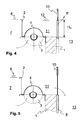
- FIG. 1 Another embodiment of the damming element is shown in FIG.
- the baffle element 8 ' is not rotatably arranged on the intermediate wall 1, but it is arranged vertically displaceable on the outflow side 13.
- the storage element 8 ' can be lowered to change the effective storage area with the hydraulic cylinder 10.
- the upper edge of the baffle element 8 ' is thereby moved in the direction of the top of the intermediate wall 1, whereby the effective height H w is reduced.
- the water from the storage space 10 then flows over the upper edge of the storage element 8 'to the outflow side 13.
- Figure 5 shows the embodiment of Figure 4, wherein the baffle element 8 'is in the cleaning position.
- the effective height H w of the damming element 8 ' is in this state 0.
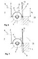
- Figures 6 and 7 show substantially the same embodiment as is the case with FIGS. 4 and 5.
- the difference is that the damming element 8 'rests on the inflow side 7 is retractable. It may be similar to the embodiment 3, the storage element 8 'on the on the sieve 4 or be attached to the housing of the screening plant. A pre-assembly of the storage element 8 'together with the screw 3 and the wire 4 can hereby be performed.
- the baffle 2 is also on the housing of the sieve, in particular attached to the wire 4. It can as in the illustrated embodiments be made of sheet metal. Of course she can too be concreted and thus the guiding function for guiding the water of the Inflow side 7 through the sieve in the storage space 10 and thus to the discharge side 13 effect.
- the baffle 8 ' are not only lowered into, but can also be brought into a raised position.
- the inflow not over the upper edge of the storage element 8 'but over the lower edge thereof respectively.
- This creates a gap between the top of the partition 1 and the underside of the baffle element 8 ', through which the Water can flow into the discharge side 13.
- the effective height of the damming element 8 'then lies between the water level 12 of the storage space 11th and the lower edge of the baffle element 8 '.
- rotational movements of the storage element 8 are not just about one horizontal axis 9, but also on vertical axes, not shown possible.
- the baffle element 8 is thereby rotated about the vertical axis and opens in two places a gap through which the water from the storage space 11 can flow into the discharge side 13.
Abstract
Description
Die vorliegende Erfindung betrifft eine Abwasseranlage mit einer Zuflussseite für verunreinigtes Wasser und eine Abflussseite für gereinigtes Wasser, mit einer Tauchwand auf der Zuflussseite und einer Zwischenwand zur Abtrennung der Zuflussseite von der Abflussseite, wobei zwischen der Tauchwand und der Zwischenwand eine Siebanlage mit einer Schneckenwendel und einem die Schneckenwendel teilweise umgebenden Sieb angeordnet ist. Weiterhin betrifft die Erfindung ein Verfahren zum Betätigen eines Stauelementes einer Abwasseranlage zwischen einer Zuflussseite für verunreinigtes Wasser und einer Abflussseite für gereinigtes Wasser, wobei die wirksame Höhe des Stauelementes in Abhängigkeit der Menge des anfallenden Wassers gesteuert wird.The present invention relates to a sewage plant with an inflow side for contaminated water and a discharge side for purified water, with a baffle on the inflow side and an intermediate wall for separation the inflow side from the discharge side, being between the diving wall and the intermediate wall a sieve with a spiral screw and a the screw spiral is arranged partially surrounding sieve. Farther The invention relates to a method for actuating a storage element a sewage plant between an inflow side for contaminated Water and a discharge side for purified water, the effective Height of the damming element as a function of the amount of accumulated water is controlled.
Aus der EP 0 614 397 B1 ist eine Abwasseranlage mit eingebauter Siebrecheneinheit bekannt. Zwischen einer Zuflussseite und einer Abflussseite ist eine Zwischenwand vorgesehen, auf der eine Reinigungsvorrichtung in Form eines Siebrechens angeordnet ist. Zur Erhöhung des Stauvolumens befindet sich in Fließrichtung hinter dem Siebrechen ein zur Vertikalebene geneigtes Stauelement. Mit diesem Stauelement wird die Durchtrittsgeschwindigkeit sowie die Druckverteilung des Wassers bezüglich des Siebrechens vergleichmäßigt. Die offenbarte Vorrichtung hat den Nachteil, dass insbesondere Schweb- und Sinkstoffe, wie z.B. Sand, das geneigt ausgebildete Stauelement nicht überwinden können. Insbesondere nach großen Regenereignissen sammeln sich dort Verunreinigungen und führen zu einem erhöhten Verschleiss zwischen Siebrechen und Rechenreiniger. EP 0 614 397 B1 discloses a wastewater installation with a built-in screening unit known. Between an inflow side and an outflow side is an intermediate wall provided on which a cleaning device in the form a Siebrechens is arranged. To increase the storage volume is located in the flow direction behind the screen rake inclined to the vertical plane Storage element. With this baffle element, the passage speed and the pressure distribution of the water with respect to the crushing evened out. The disclosed device has the disadvantage that, in particular Suspended solids and sediments, e.g. Sand, the inclined formed damming element can not overcome. Especially after big rain events there accumulate impurities and lead to an increased Wear between screen rake and rake cleaner.
Aus der DE 33 05 409 A1 ist ein Regenabschlagwerk zur Trennung von Schmutz- und Regenwasser mit einem zwischen Kanal und Kläranlage angeordneten Stauraum, in dem eine Tauchwand einen abschlagseitigen Raum abteilt, bekannt. Zwischen der Unterkante der Tauchwand und der Wandung des Stauraums ist ein Grobfilter angeordnet. Über einen in dem kanalseitigen Stauraum angeordneten Schwimmer ist über einen Waagebalken, dessen Drehachse oberhalb der Tauchwand liegt, eine Klappe verbunden, welche als Stauelement dient. In Abhängigkeit des Wasserstandes wird die wirksame Höhe des Stauelements beeinflusst, indem das Stauelement um eine Drehachse abgesenkt oder angehoben wird. Nachteilig ist hierbei, dass der Grobfilter keine Reinigungseinrichtung aufweist und somit für Inspektionszwecke schwer zugänglich ist. Auch bei vollständig geöffnetem Stauelement ist der Grobfilter unterhalb des Wasserspiegels und somit nicht zugänglich.From DE 33 05 409 A1 is a Regenabschlagwerk for the separation of Dirt and rainwater with a between channel and sewage treatment plant arranged Storage space, in which a baffle wall a knock-off room divulges, known. Between the lower edge of the diving wall and the wall the storage space is a coarse filter arranged. About one in the channel side Storage space arranged float is via a balance beam, whose Rotary axis is above the baffle wall, a flap connected, which serves as a stowage element. Depending on the water level, the effective Height of the baffle influenced by the baffle around a Rotary axis is lowered or raised. The disadvantage here is that the Coarse filter has no cleaning device and thus for inspection purposes is difficult to access. Also with completely opened storage element is the coarse filter below the water level and therefore not accessible.
Aufgabe der vorliegenden Erfindung ist es daher, eine Anlage und ein Verfahren zu schaffen, mit welchen einerseits der Wasserstand in einem Becken steuerbar ist und andererseits eine Siebeinrichtung, welche Schmutz aus dem Abwasser filtert, zu Wartungszwecken leicht zugänglich ist.The object of the present invention is therefore an installation and a method to create, on the one hand, the water level in a basin is controllable and on the other hand, a sieve, which is dirt filtered wastewater, is easily accessible for maintenance purposes.
Die Aufgabe wird gelöst mit einer Abwasseranlage und einem Verfahren der unabhängigen Ansprüche.The problem is solved with a sewage plant and a method of independent claims.
Die erfindungsgemäße Abwasseranlage weist eine Zuflussseite für verunreinigtes Wasser und eine Abflussseite für gereinigtes Wasser auf. Auf der Zuflussseite ist eine Tauchwand angeordnet. Die Zuflussseite und die Abflussseite sind mittels einer Zwischenwand voneinander getrennt. Zwischen der Tauchwand und der Zwischenwand ist eine Siebanlage mit einer Schnekkenwendel und ein die Schneckenwendel teilweise umgebendes Sieb angeordnet. Auf der Verlängerung der Zwischenwand ist ein Stauelement angeordnet, dessen wirksame Staufläche veränderbar ausgebildet ist und das zumindest in seiner größten Erstreckung über die Schneckenwendel und das Sieb hinausragt.The wastewater treatment plant according to the invention has an inflow side for contaminated Water and a drain for purified water. On the inflow side is arranged a diving wall. The inflow side and the outflow side are separated by an intermediate wall. Between the Submerged wall and the intermediate wall is a sieve with a Schnekkenwendel and a sieve partially surrounding the screw arranged sieve. On the extension of the intermediate wall a baffle element is arranged, the effective storage area is formed changeable and the at least in its greatest extent about the helix and the spiral Sieve protrudes.
Durch die veränderbare Staufläche des Stauelementes wird vorteilhafterweise bewirkt, dass eine Regulierung des Wasserstandes auf der Zuflussseite ermöglicht wird. Bei einer großen Wassermenge auf der Zuflussseite wird die wirksame Staufläche des Stauelementes verringert, so dass mehr Wasser abfließen kann und das Wasserniveau auf der Zuflussseite insgesamt etwa gleich bleibt. Das Wasser, welches von der Zuflussseite in die Abflussseite gelangt, durchströmt hierbei die Siebanlage mit der Schneckenwendel und dem Sieb. Verunreinigungen bleiben in dem Sieb hängen und werden mit Hilfe der sich drehenden Schneckenwendel an das Ende der Schneckenwendel befördert und können dort aus der Abwasseranlage entnommen werden. Die wirksame Staufläche, d. h. die Projektion des Stauelementes auf das rückgestaute Wasser, beeinflusst dabei die Höhe des rückgestauten Wasserspiegels. Das Wasser, welches insbesondere von unten durch die Siebanlage hindurchtritt, vergrößert seine Fließgeschwindigkeit in Abhängigkeit davon, wie viel Wasser durch das wehrartige Stauelement freigegeben wird. Erstreckt sich das Stauelement zumindest in seiner größten wirksamen Staufläche bis über die Schneckenwendel und das Sieb hinaus, so wird vorteilhafterweise bewirkt, dass das komplette Sieb durchströmt wird und somit eine sehr gute Reinigungswirkung und ein sehr guter Abtransport der Verunreinigungen möglich wird.Due to the variable storage area of the storage element is advantageously causes a regulation of the water level on the inflow side is possible. With a large amount of water on the inflow side is the effective storage area of the storage element is reduced, allowing more water can drain and the water level on the inflow side total about stays the same. The water flowing from the inflow side into the outflow side passes, flows through the screen with the spiral screw and the sieve. Contaminants will stick in the sieve and become with Help of the rotating helix to the end of the helix transported there and can be taken there from the sewage plant. The effective storage area, d. H. the projection of the storage element on the backwater, thereby affecting the height of the backlogged Water table. The water, especially from below through the Screening passes, increases its flow rate in dependence of how much water is released by the weir-like damming element becomes. The baffle extends at least in its largest effective Staufläche beyond the helix and the sieve addition, it is advantageous causes the complete strainer to flow through and thus a very good cleaning effect and a very good removal of impurities becomes possible.
Besonders vorteilhaft ist es, wenn die wirksame Staufläche in ihrer Höhe veränderbar ausgebildet ist. Hierdurch wird die Unterkante des Stauelementes entweder angehoben oder die Oberkante des Stauelementes abgesenkt. Das aufgestaute Wasser über- oder unterströmt damit das Stauelement und sorgt auf der gesamten Länge des Stauelementes für eine gleichmäßige Strömung durch die Siebanlage. Die Reinigung des Abwassers wird damit schnell und gleichmäßig bewirkt. Eine stark ungleichmäßige Ansammlung von Verunreinigungen in der Siebanlage kann ebenfalls vermieden werden. It is particularly advantageous if the effective storage area in height is formed changeable. As a result, the lower edge of the storage element either raised or lowered the top of the baffle. The dammed up water flows under or under the baffle element and ensures uniform over the entire length of the baffle element Flow through the sieve. The purification of the wastewater is with it effected quickly and evenly. A very uneven collection contamination in the sieve can also be avoided.
Vorteilhaft ist es, wenn das Stauelement um eine horizontale und vertikale Achse schwenkbar gelagert ist. Bei der Lagerung um eine horizontale Achse wird das Stauelement derart verschwenkt, dass das von der Achse abgewandte Stauelement sich in der Projektion zur rückstauenden Wasserfläche der Achse nähert und hierdurch die wirksame Staufläche verringert wird. Bei einem Zurückschwenken wird die wirksame Staufläche wiederum vergrößert und bewirkt somit eine größere Rückstauwirkung als zuvor. Bei der Lagerung um eine vertikale Achse werden die Seiten des Stauelementes verschwenkt. Auch hierdurch wird die wirksame Staufläche bzgl. des rückgestauten Wassers verändert, wodurch Wasser zurückgehalten oder mehr oder weniger schnell abgelassen werden kann.It is advantageous if the baffle element about a horizontal and vertical Axis is pivotally mounted. When stored around a horizontal axis the baffle is pivoted so that the remote from the axis Stowage element in the projection to the backwater approaching the axis and thereby reducing the effective storage area. at pivoting back the effective storage area is in turn increased and thus causes a greater backflow effect than before. During storage about a vertical axis, the sides of the storage element are pivoted. This also makes the effective storage area with respect to the backwater changed, causing water to be retained or more or less can be drained quickly.
In einer weiteren vorteilhaften Ausführung ist das Stauelement vertikal verschieblich gelagert. Im Gegensatz zu einer Verschwenkung des Stauelementes wird hierbei das Stauelement nach unten oder oben verschoben und hierdurch die Rückstaukante des Stauelementes in seiner Position verändert. Gegenüber einer geschlossenen Stellung wird dabei das Stauelement entweder angehoben, wodurch sich ein Spalt zwischen der abgesenkten Position und der angehobenen Position bildet, durch welche das Wasser in die Abflussseite einströmen kann, oder das Stauelement wird abgesenkt, wodurch die obere Staukante mehr oder weniger unter den Wasserspiegel gelangt und hierdurch jedenfalls das Einströmen des Wassers in die Abflussseite mehr oder weniger erlaubt.In a further advantageous embodiment, the storage element is vertically displaceable stored. In contrast to a pivoting of the storage element In this case, the baffle is moved down or up and As a result, the return edge of the storage element changed in position. Compared to a closed position while the storage element is either raised, creating a gap between the lowered position and the raised position through which the water in the Outflow side can flow, or the baffle is lowered, causing the upper edge of the dam gets more or less under the water level and thereby at least the influx of water into the drainage side more or less allowed.
Besonders vorteilhaft ist das Stauelement an der Zwischenwand anzuordnen. Die Zwischenwand ist üblicherweise so stabil aufgebaut, dass sie das Stauelement, dessen Lagerung und insbesondere die Kräfte beim Rückstauen des Wassers aufnehmen kann.Particularly advantageously, the storage element is to be arranged on the intermediate wall. The partition is usually built so stable that they Stowage element, its storage and in particular the forces during backwater of the water.
Ist das Stauelement an der Siebanlage angeordnet, so ist es in vorteilhafterweise besonders einfach zu montieren. Es kann bereits zusammen mit der Siebanlage vormontiert und zur Baustelle gebracht werden und dort in sehr kurzer Zeit beispielsweise an die Zwischenwand angebaut werden.If the damming element is arranged on the sieve system, then it is advantageous especially easy to assemble. It can already be done with the Screening plant pre-assembled and brought to the site and there in very be grown for a short time, for example, to the partition.
Die Tauchwand dient zur Wasserleitung, wodurch das Wasser gezwungen wird auf dem Weg von der Zuflussseite zur Abflussseite durch die Siebanlage hindurch zu strömen. Auf die Tauchwand entstehen üblicherweise keine großen Kräfte, so dass sie sehr einfach an einem Gehäuse der Siebanlage angeordnet sein kann. Häufig ist es auch ausreichend, dass die Tauchwand ein Blech, insbesondere ein Edelstahlblech ist, welches mit dem Gehäuse der Siebanlage verbunden ist. Die Tauchwand ragt dabei bis oberhalb des Wasserspiegels, so dass die Strömung durch die Siebanlage gewährleistet ist.The baffle wall is used for water supply, which forced the water is on the way from the inflow side to the outflow side through the sieve to flow through. On the baffle usually arise no great forces, making them very easy on a housing of the sieve can be arranged. Often it is also sufficient that the diving wall a sheet, in particular a stainless steel sheet, which is connected to the housing the screening plant is connected. The diving wall protrudes above the Water level, so that ensures the flow through the sieve is.
Umgibt das Sieb die Schneckenwendel im wesentlichen in ihrer oberen Hälfte, so wird das fließende Wasser mit den Verunreinigungen an der Schnekkenwendel vorbei und schließlich durch das Sieb hindurch geleitet. Die Verunreinigungen bleiben an dem Sieb im Bereich der Schneckenwendel hängen und können bei einer Bewegung der Schneckenwendel an das Ende der Schneckenwendel hin befördert werden. Wichtig ist die Durchströmung der Siebanlage im wesentlichen von unten nach oben.The sieve surrounds the helix essentially in its upper half, so does the flowing water with the impurities at the snail spiral passed and finally passed through the sieve. The impurities stick to the sieve in the area of the spiral helix and may be at a movement of the screw spiral to the end of Schneckenwendel be promoted. Important is the flow through the Sieve plant essentially from bottom to top.
Erfindungsgemäß ragt das Stauelement in seiner größten Erstreckung bis über die Schneckenwendel und das Sieb hinaus. Besonders vorteilhaft ist es, wenn zusätzlich die Zwischenwand bis im wesentlichen zu der Höhe der Achse der Schneckenwendel reicht und im Anschluss daran das Stauelement beginnt. Das Stauelement wirkt hierdurch etwa ab der Höhe der Achse der Schneckenwendel im Bereich des Siebes. Eine Reinigung des Raumes zwischen dem Stauelement und dem Sieb bzw. der Tauchwand ist hierdurch sehr einfach möglich, indem das Stauelement beispielsweise komplett geöffnet wird und somit dieser Raum von Wasser durchströmt und Verunreinigungen, welche durch das Sieb gelangt sind, aus diesem Raum entfernt werden können. Selbstverständlich ist auch eine manuelle Reinigung dieses Bereiches möglich. Auch diese Art der Reinigung ist einfacher durchzuführen, wenn in der Reinigungsstellung des Stauelementes kein schlecht zugänglicher Bereich vorhanden ist.According to the invention the blocking element protrudes in its greatest extent beyond the helix and the sieve. It is particularly advantageous in addition, if the intermediate wall to substantially the height of Axis of the screw flight reaches and then the baffle element starts. The baffle thus acts approximately from the height of the axis the spiral of spiral in the area of the sieve. A cleaning of the room between the baffle element and the sieve or the baffle wall is characterized very easily possible by the baffle, for example, completely open and thus this space flows through water and impurities, which have passed through the sieve are removed from this space can. Of course, also a manual cleaning of this area possible. Also, this type of cleaning is easier to perform, if in the cleaning position of the storage element no bad accessible Area is present.
Vorteilhafterweise ist dem Stauelement eine Hydraulikeinrichtung zur Bewegung des Stauelementes zugeordnet. Die Hydraulikeinrichtung ermöglicht je nach Bauweise des Stauelementes ein Anheben, Absenken und/oder Drehen des Stauelementes um eine Achse. Alternativ kann auch eine Triebstockkonstruktion oder ein Spindelantrieb zur Bewegung des Stauelementes vorgesehen sein. Je nach Anwendungsfall kann auch eine derartige Konstruktion vorteilhaft sein.Advantageously, the storage element is a hydraulic device for movement associated with the storage element. The hydraulic device allows ever according to construction of the storage element lifting, lowering and / or turning of the storage element about an axis. Alternatively, a drive train construction or a spindle drive for moving the storage element be provided. Depending on the application, such a construction be beneficial.
Ist in der Zwischenwand eine Öffnung zur Aufnahme des Stauelementes angeordnet, so kann das Stauelement vorteilhafterweise in der Zwischenwand versenkt werden. Das Stauelement und ggf. die Ansteuerungsmechanik für das Stauelement können hier geschützt aufbewahrt werden.Is disposed in the intermediate wall an opening for receiving the storage element, so the storage element can advantageously in the intermediate wall be sunk. The baffle element and possibly the drive mechanism for The storage element can be kept protected here.
Ist das Stauelement in Teilflächen unterteilt, so kann eine dosiertere Öffnung und Schließung des Wehrs erfolgen, indem nur einzelne der Teilflächen bewegt werden.If the baffle element is subdivided into subareas, then a more metered opening can be used and closing the weir by moving only a few of the faces become.
In einem erfindungsgemäßen Verfahren zum Betätigen eines Stauelementes einer Abwasseranlage zwischen einer Zuführseite für verunreinigtes Wasser und einer Abflussseite für gereinigtes Wasser wird die wirksame Höhe des Stauelementes in Abhängigkeit der Menge des anfallenden Wassers gesteuert. Zu Wartungszwecken und/oder Reinigungszwecken, insbesondere nach großen Regenereignissen, wird das Stauelement in eine Reinigungsstellung bewegt. Hierdurch wird der zuflussseitige Raum des Stauelementes von Verunreinigungen, welche durch das Stauelement aufgestaut wurden oder vor dem Stauelement abgesunken sind, ausgeschwemmt oder können im wasserlosen Zustand leicht zugänglich entfernt werden. In a method according to the invention for actuating a storage element a sewage plant between a supply side for contaminated water and a purified water discharge side will be the effective height of the Stowage element controlled depending on the amount of water produced. For maintenance and / or cleaning purposes, especially after large rain events, the baffle element is in a cleaning position emotional. As a result, the inflow-side space of the storage element of Impurities that have been dammed up by the damming element or have sunk in front of the damming element, flushed out or can in waterless condition easily accessible.
Für die Reinigungsstellung wird das Stauelement vorzugsweise angehoben. Hierdurch wird der Raum, in welchem sich Sinkstoffe vor dem Stauelement abgelagert haben, durchspült. Die Sinkstoffe werden hierdurch entfernt.For the cleaning position, the damming element is preferably raised. As a result, the space in which suspended matter in front of the storage element have rinsed, rinsed. The sediments are thereby removed.
Wird das Stauelement vorteilhafterweise im wesentlichen vollständig abgesenkt, so werden nicht nur die Sinkstoffe, sondern auch vor dem Stauelement aufgestaute Schwimmstoffe ausgeschwemmt und führen so zu einer Reinigung des Raumes vor dem Stauelement.If the storage element is advantageously lowered substantially completely, So not only the sediment, but also before the damming element dammed up floating matter and thus lead to a Cleaning the room in front of the storage element.
Weitere Vorteile der Erfindung werden in den nachfolgenden Ausführungsbeispielen beschrieben. Es zeigt
-
Figur 1 - einen Ausschnitt einer Abwasseranlage im Querschnitt mit einem beweglichen Stauelement,
-
Figur 2 - eine Abwasseranlage gemäß Figur 1 mit einem seitlich angeordneten Stauelement,
-
Figur 3 - eine Abwasseranlage gemäß Figur 1 mit einem an einer Siebanlage angeordneten Stauelement,
-
Figur 4 und 5 - eine Abwasseranlage gemäß Figur 1 mit einem verschieblich angeordneten Stauelement und
-
Figur 6 und 7 - eine Abwasseranlage gemäß Figur 1 mit einem an der Siebanlage angeordneten verschieblichen Stauelement.
- FIG. 1
- a detail of a wastewater treatment plant in cross section with a movable storage element,
- FIG. 2
- a wastewater treatment plant according to FIG. 1 with a laterally arranged damming element,
- FIG. 3
- a wastewater treatment plant according to FIG. 1 with a stowage element arranged on a sieve plant,
- FIGS. 4 and 5
- a wastewater treatment plant according to Figure 1 with a displaceably arranged storage element and
- FIGS. 6 and 7
- a wastewater treatment plant according to Figure 1 with a arranged on the sieve sliding displaceable element.
Figur 1 zeigt einen Querschnitt einer Abwasseranlage im Bereich einer Zwischenwand
1 und einer Tauchwand 2. Zwischen der Zwischenwand 1 und
der Tauchwand 2 ist eine Siebanlage mit einer Schneckenwendel 3 und einem
Sieb 4 angeordnet. Die Zwischenwand 1 endet etwa in der Höhe einer
Achse 5 der Schneckenwendel 3. Die Tauchwand 2 erstreckt sich etwa von
der Höhe der Achse 5 der Schneckenwendel 3 bis zur Höhe des maximal
zulässigen Wasserspiegels 6 der Zuflußseite 7. Das Sieb 4 reicht im wesentlichen
von der Zwischenwand 1 bis zur Tauchwand 2 und umgibt die obere
Hälfte der Schneckenwendel 3.FIG. 1 shows a cross-section of a wastewater treatment plant in the region of an
Auf der Zwischenwand 1 ist ein Stauelement 8 angeordnet. Das Stauelement
8 ist an seinem der Zwischenwand 1 zugewandten Ende in einer horizontal
angeordneten Achse 9 gelagert. An dem der Zwischenwand 1 abgewandten
Ende des Stauelements 8 ist ein Hydraulikzylinder 10 angeordnet. Durch eine
Betätigung des Hydraulikzylinders 10 ist das Stauelement 8 aus der dargestellten
vertikalen Position in eine gestrichelt dargestellte horizontale Position
oder jede dazwischen liegende Position drehbar. Es wird hierdurch ein
Stauraum 11 gebildet, welcher von der Oberkante des Stauelements 8 abhängig
ist. In der dargestellten vertikalen Position wird das Wasser in dem
Stauraum 11 bis zu einem Wasserspiegel 12 aufstaubar sein, da die wirksame
Staufläche des Stauelements bis zu einer vertikalen Höhe und damit der
tatsächlichen Höhe des Stauelements 8 entspricht. Ist das Stauelement in
einer gedrehten Position, so ist die wirksame Staufläche geringer und der
Wasserspiegel 12 des Stauraums dementsprechend niedriger. Es wird hierdurch
mehr Wasser aus dem Stauraum 11 und damit aus der Zuflussseite 7
in eine Abflussseite 13 strömen. In einer geneigten Position des Stauelements
8, wie sie beispielsweise durch die strich-punktierte Darstellung des
Stauelements 8 gezeigt ist, weist das Stauelement 8 eine gegenüber der vertikalen
Position verringerte wirksame Staufläche auf, welche durch die vertikale
Höhe Hw bestimmt ist.On the
Das Wasser strömt von der Zuflussseite 7 durch die Schneckenwendel 3 und
das Sieb 4 in den Stauraum 11. Das Sieb 4 reinigt hierbei das Abwasser von
Teilen, welche von dem Abwasser mitgeführt werden. Durch eine Drehung
der Schneckenwendel 3 werden diese Teile an das Ende der Schneckenwendel
3 befördert und können dort entnommen werden. Materialien, welche
nicht von dem Sieb 4 zurückgehalten werden können, gelangen in den Stauraum
11. Insbesondere Sinkstoffe, welche sich in dem Wasser des Stauraums
11 befinden, werden sich auf der Zwischenwand 11 und vor dem
Stauelement 8 ablagern. Bei großen Regenereignissen kann dies in größerem
Umfang stattfinden. Erfindungsgemäß wird daher das Stauelement 8 zu
Reinigungs- aber auch zu Wartungszwecken in eine mindestens horizontale
Lage verdreht, wodurch Wasser, welches aus der Zuflussseite 7 zur Abflussseite
13 strömt, die auf der Zwischenwand 1 abgelagerten Sinkstoffe mitreißt
und damit den Stauraum 11 reinigt. Wird diese Reinigungsstellung des Stauelements
8 in vorbestimmten Abständen eingenommen, so wird eine Reinigung
des Stauraums 11 weitgehend selbsttätig ohne manuellen Eingriff möglich
sein. Verunreinigungen, welche sich dennoch in dem Stauraum 11 ablagern,
können aufgrund der Beweglichkeit des Stauelements 8 und der damit
verbundenen guten Zugänglichkeit zusätzlich leicht manuell gereinigt werden.The water flows from the
Figur 2 zeigt eine ähnliche Anordnung des Stauelements 8 an der Zwischenwand
1 wie Figur 1. Während bei Figur 1 die Achse 9 an der Oberseite
der Zwischenwand 1 befestigt ist, befindet sie sich in dem Ausführungsbeispiel
der Figur 2 auf der abflußseitigen Seite der Zwischenwand 1. Durch die
Anordnung der Achse 9 unterhalb der Oberseite der Zwischenwand 1 kann
das Stauelement 8 insbesondere zum Einnehmen der Reinigungsstellung so
abgesenkt werden, daß die Oberseite der Zwischenwand 1 vollständig von
dem abströmenden Wasser gereinigt werden kann.Figure 2 shows a similar arrangement of the
Das Stauelement 8 bildet auch bei dem Ausführungsbeispiel der Figur 2 eine
Verlängerung der Zwischenwand 1 bis über das Sieb 4 hinaus. Hierdurch
wird das Sieb 4 beim Durchtritt des Wassers von der Zuflussseite 7 zum
Stauraum 11 und der Abflussseite 13 vollständig durchspült und verhindert
dabei, daß sich Verunreinigungen des Wassers der Abflussseite 13 nur an
einzelnen Stellen des Siebes 4 ansammeln und gegebenenfalls sogar zu
einer Verstopfung des Siebes 4 führen würden. The
Ein weiteres Ausführungsbeispiel der Anordnung des Stauelements 8 zeigt
die Figur 3. Bei dieser Ausführung ist das Stauelement 8 an dem Sieb 4 befestigt.
Es kann hierdurch beispielsweise eine Vormontage des Stauelements
8 an dem Gehäuse des Siebs 4 erfolgen. Die nahezu fertige Baueinheit kann
anschließend vor Ort an die Zwischenwand 1 montiert werden. Diese Vorgehensweise
reduziert den Aufwand an der Baustelle und senkt somit die Montagekosten.Another embodiment of the arrangement of the
Eine andere Ausführung des Stauelements ist in Figur 4 dargestellt. Das
Stauelement 8' ist hierbei nicht drehbar an der Zwischenwand 1 angeordnet,
sondern es ist vertikal verschiebbar auf der Abflussseite 13 angeordnet. Das
Stauelement 8' kann dabei zum Verändern der wirksamen Staufläche mit
dem Hydraulikzylinder 10 abgesenkt werden. Die Oberkante des Stauelements
8' wird dabei in Richtung auf die Oberseite der Zwischenwand 1 bewegt,
wodurch die wirksame Höhe Hw reduziert wird. Das Wasser aus dem
Stauraum 10 strömt sodann über die Oberkante des Stauelements 8' zur Abflussseite
13.Another embodiment of the damming element is shown in FIG. The baffle element 8 'is not rotatably arranged on the
Figur 5 zeigt das Ausführungsbeispiel aus Figur 4, wobei sich das Stauelement
8' in der Reinigungsstellung befindet. Die Oberkante des Stauelements
8' befindet sich dabei in Höhe der Oberkante der Zwischenwand 1. Die wirksame
Höhe Hw des Stauelements 8' beträgt in diesem Zustand 0. Das Wasser,
welches in der dargestellten Pfeilrichtung von der Zuflussseite 7 durch
die Schneckenwendel 3 und das Sieb 4 strömt, tritt ohne Rückstauwirkung
sofort in den Bereich der Abflussseite 13 ein. Sinkstoffe, welche sich in dem
Stauraum 10 abgelagert haben, werden in dieser Reinigungsstellung des
Stauelements 8' in die Abflussseite 13 geschwemmt.Figure 5 shows the embodiment of Figure 4, wherein the baffle element 8 'is in the cleaning position. The effective height H w of the damming element 8 'is in this state 0. The water, which in the direction of the arrow from the
Die Figuren 6 und 7 zeigen im wesentlichen das gleiche Ausführungsbeispiel
wie Figuren 4 und 5. Unterschiedlich ist hierbei, dass das Stauelement 8' auf
der Zuflussseite 7 versenkbar ist. Es kann hierbei ähnlich wie bei dem Ausführungsbeispiel
der Figur 3 das Stauelement 8' an dem an dem Sieb 4 bzw.
dem Gehäuse der Siebanlage befestigt sein. Eine Vormontage des Stauelements
8' zusammen mit der Schneckenwendel 3 und dem Sieb 4 kann hierbei
durchgeführt werden.Figures 6 and 7 show substantially the same embodiment
as is the case with FIGS. 4 and 5. Here, the difference is that the damming element 8 'rests on
the
Die Tauchwand 2 ist ebenfalls an dem Gehäuse der Siebanlage, insbesondere
an dem Sieb 4 befestigt. Sie kann wie in den dargestellten Ausführungsbeispielen
aus Blech gefertigt sein. Selbstverständlich kann sie auch
betoniert sein und damit die Leitfunktion zum Führen des Wassers von der
Zuflussseite 7 durch die Siebanlage in den Stauraum 10 und damit zur Abflussseite
13 hin bewirken.The
Die vorliegende Erfindung ist nicht auf die Ausführungsbeispiele beschränkt.
Insbesondere sind das Stauelement 8' nicht nur in die abgesenkte, sondern
auch in eine angehobene Stellung verbringbar. Hierdurch wird der Zufluß
nicht über die Oberkante des Stauelements 8' sondern über deren Unterkante
erfolgen. Es entsteht hierbei ein Spalt zwischen der Oberseite der Zwischenwand
1 und der Unterseite des Stauelements 8', durch welchen das
Wasser in die Abflussseite 13 strömen kann. Die wirksame Höhe des Stauelements
8' liegt dann zwischen dem Wasserspiegel 12 des Stauraums 11
und der Unterkante des Stauelements 8'.The present invention is not limited to the embodiments.
In particular, the baffle 8 'are not only lowered into, but
can also be brought into a raised position. As a result, the inflow
not over the upper edge of the storage element 8 'but over the lower edge thereof
respectively. This creates a gap between the top of the
Außerdem sind Drehbewegungen des Stauelements 8 nicht nur über eine
horizontale Achse 9, sondern auch über nicht dargestellte vertikale Achsen
möglich. Das Stauelement 8 wird dabei um die vertikale Achse verdreht und
öffnet an zwei Stellen einen Spalt, durch welchen das Wasser aus dem Stauraum
11 in die Abflussseite 13 fließen kann.In addition, rotational movements of the
Claims (17)
Applications Claiming Priority (2)
| Application Number | Priority Date | Filing Date | Title |
|---|---|---|---|
| DE102004014762 | 2004-03-26 | ||
| DE102004014762A DE102004014762A1 (en) | 2004-03-26 | 2004-03-26 | Wastewater plant and method for actuating a damming element of a wastewater treatment plant |
Publications (2)
| Publication Number | Publication Date |
|---|---|
| EP1580339A2 true EP1580339A2 (en) | 2005-09-28 |
| EP1580339A3 EP1580339A3 (en) | 2006-08-16 |
Family
ID=34854057
Family Applications (1)
| Application Number | Title | Priority Date | Filing Date |
|---|---|---|---|
| EP05101565A Withdrawn EP1580339A3 (en) | 2004-03-26 | 2005-03-01 | Waste water installation and method for actuating a weir element of a waste water installation |
Country Status (2)
| Country | Link |
|---|---|
| EP (1) | EP1580339A3 (en) |
| DE (1) | DE102004014762A1 (en) |
Cited By (1)
| Publication number | Priority date | Publication date | Assignee | Title |
|---|---|---|---|---|
| DE102018109692A1 (en) | 2018-04-23 | 2019-10-24 | Huber Se | Separation for a sewer and procedures for emergency discharge of a sewer |
Citations (2)
| Publication number | Priority date | Publication date | Assignee | Title |
|---|---|---|---|---|
| DE3305409A1 (en) | 1983-02-17 | 1984-08-23 | Anton 5788 Winterberg Kanand | Storm separation works |
| US20040028474A1 (en) | 2000-08-29 | 2004-02-12 | Woodbridge Barrie Christopher | Screen assembly for combined sewer overflow weir |
Family Cites Families (5)
| Publication number | Priority date | Publication date | Assignee | Title |
|---|---|---|---|---|
| CH678281A5 (en) * | 1988-10-14 | 1991-08-30 | Werner Nill | |
| CH685554A5 (en) * | 1992-09-25 | 1995-08-15 | Romag Roehren & Masch | Sewage system with built-in screening rake. |
| AT400599B (en) * | 1993-04-30 | 1996-01-25 | Nill Werner | SCREEN ARRANGEMENT FOR OVERFLOW POOLS |
| EP0783056B1 (en) * | 1996-01-08 | 2001-11-21 | VA TECH WABAG Schweiz AG | Device for dividing with control an arriving fluid flow |
| DE20103875U1 (en) * | 2001-03-07 | 2001-08-16 | Vollmar Gmbh | Sewage system with cleaning device |
-
2004
- 2004-03-26 DE DE102004014762A patent/DE102004014762A1/en not_active Withdrawn
-
2005
- 2005-03-01 EP EP05101565A patent/EP1580339A3/en not_active Withdrawn
Patent Citations (2)
| Publication number | Priority date | Publication date | Assignee | Title |
|---|---|---|---|---|
| DE3305409A1 (en) | 1983-02-17 | 1984-08-23 | Anton 5788 Winterberg Kanand | Storm separation works |
| US20040028474A1 (en) | 2000-08-29 | 2004-02-12 | Woodbridge Barrie Christopher | Screen assembly for combined sewer overflow weir |
Cited By (1)
| Publication number | Priority date | Publication date | Assignee | Title |
|---|---|---|---|---|
| DE102018109692A1 (en) | 2018-04-23 | 2019-10-24 | Huber Se | Separation for a sewer and procedures for emergency discharge of a sewer |
Also Published As
| Publication number | Publication date |
|---|---|
| DE102004014762A1 (en) | 2005-10-06 |
| EP1580339A3 (en) | 2006-08-16 |
Similar Documents
| Publication | Publication Date | Title |
|---|---|---|
| DE202009010367U1 (en) | Device for separating rainwater from chemically, biologically and / or toxic polluted wastewater | |
| EP1366245B1 (en) | Waste water installation with purification device | |
| AT400599B (en) | SCREEN ARRANGEMENT FOR OVERFLOW POOLS | |
| DE202008012099U1 (en) | Improved waste water intake | |
| DE4139572C2 (en) | Sieve arrangement for circular rainwater relief systems | |
| EP0722524B1 (en) | Tank system | |
| DE4023557C2 (en) | ||
| DE202007014331U1 (en) | Sewerage inlet | |
| DE3510171A1 (en) | Liquid-retention device for installation into a liquid-storage chamber | |
| EP1632619A1 (en) | Device for controlling overflow in water installations | |
| EP1580339A2 (en) | Waste water installation and method for actuating a weir element of a waste water installation | |
| DE4015414C2 (en) | Overflow structure with retention device for floating materials in mixed sewage systems | |
| DE19517101C1 (en) | Removal system for floating solids in rainwater overflow | |
| EP3751067A1 (en) | Pipe sedimentation system | |
| DE4125453A1 (en) | Device for collecting and cleaning rain water - solid impurities are sepd. by reducing flow rate and/or coarse filtration in inlet section to flow equalisation channel | |
| DE202009016167U1 (en) | Dirty water inlet with safety device | |
| DE19801104C2 (en) | They break | |
| DE3205983A1 (en) | Cleaning apparatus for a sewage tank | |
| EP0565483B1 (en) | Basin in a waste water plant | |
| DE19919571C2 (en) | Sewer washer | |
| DE10253834A1 (en) | Water overflow arrangement | |
| LU503050B1 (en) | A magnetic contaminant adsorption device for waste water treatment | |
| DE102007016487B4 (en) | Liquid cleaning device with a control arrangement | |
| EP1101000B1 (en) | Device for rinsing drains | |
| AT216973B (en) | Process for the automatic temporary opening and closing of the bottom outlet of sedimentation systems and sedimentation systems for carrying out the process |
Legal Events
| Date | Code | Title | Description |
|---|---|---|---|
| PUAI | Public reference made under article 153(3) epc to a published international application that has entered the european phase |
Free format text: ORIGINAL CODE: 0009012 |
|
| AK | Designated contracting states |
Kind code of ref document: A2 Designated state(s): AT BE BG CH CY CZ DE DK EE ES FI FR GB GR HU IE IS IT LI LT LU MC NL PL PT RO SE SI SK TR |
|
| AX | Request for extension of the european patent |
Extension state: AL BA HR LV MK YU |
|
| PUAL | Search report despatched |
Free format text: ORIGINAL CODE: 0009013 |
|
| AK | Designated contracting states |
Kind code of ref document: A3 Designated state(s): AT BE BG CH CY CZ DE DK EE ES FI FR GB GR HU IE IS IT LI LT LU MC NL PL PT RO SE SI SK TR |
|
| AX | Request for extension of the european patent |
Extension state: AL BA HR LV MK YU |
|
| 17P | Request for examination filed |
Effective date: 20061006 |
|
| AKX | Designation fees paid |
Designated state(s): AT CH DE GB LI |
|
| 17Q | First examination report despatched |
Effective date: 20080220 |
|
| RAP1 | Party data changed (applicant data changed or rights of an application transferred) |
Owner name: HUBER SE |
|
| STAA | Information on the status of an ep patent application or granted ep patent |
Free format text: STATUS: THE APPLICATION IS DEEMED TO BE WITHDRAWN |
|
| 18D | Application deemed to be withdrawn |
Effective date: 20111001 |