EP1580339A2 - Installation pour eaux usées et méthode pour actionner un barrage de régulation d'une installation pour eaux usées - Google Patents
Installation pour eaux usées et méthode pour actionner un barrage de régulation d'une installation pour eaux usées Download PDFInfo
- Publication number
- EP1580339A2 EP1580339A2 EP05101565A EP05101565A EP1580339A2 EP 1580339 A2 EP1580339 A2 EP 1580339A2 EP 05101565 A EP05101565 A EP 05101565A EP 05101565 A EP05101565 A EP 05101565A EP 1580339 A2 EP1580339 A2 EP 1580339A2
- Authority
- EP
- European Patent Office
- Prior art keywords
- baffle
- installation according
- intermediate wall
- sieve
- water
- Prior art date
- Legal status (The legal status is an assumption and is not a legal conclusion. Google has not performed a legal analysis and makes no representation as to the accuracy of the status listed.)
- Withdrawn
Links
- 238000009434 installation Methods 0.000 title claims abstract description 18
- 238000000034 method Methods 0.000 title claims abstract description 9
- 239000002351 wastewater Substances 0.000 title description 7
- XLYOFNOQVPJJNP-UHFFFAOYSA-N water Substances O XLYOFNOQVPJJNP-UHFFFAOYSA-N 0.000 claims description 55
- 238000004140 cleaning Methods 0.000 claims description 19
- 238000004065 wastewater treatment Methods 0.000 claims description 9
- 238000012216 screening Methods 0.000 claims description 7
- 238000010276 construction Methods 0.000 claims description 5
- 239000008213 purified water Substances 0.000 claims description 5
- 238000012423 maintenance Methods 0.000 claims description 4
- 238000005192 partition Methods 0.000 description 8
- 239000012535 impurity Substances 0.000 description 7
- 239000013049 sediment Substances 0.000 description 6
- 239000010865 sewage Substances 0.000 description 6
- 230000009189 diving Effects 0.000 description 5
- 230000000694 effects Effects 0.000 description 4
- 238000011109 contamination Methods 0.000 description 2
- 230000000717 retained effect Effects 0.000 description 2
- 238000000926 separation method Methods 0.000 description 2
- 241000237858 Gastropoda Species 0.000 description 1
- 230000009286 beneficial effect Effects 0.000 description 1
- 230000000903 blocking effect Effects 0.000 description 1
- 239000000356 contaminant Substances 0.000 description 1
- 230000002996 emotional effect Effects 0.000 description 1
- 230000004941 influx Effects 0.000 description 1
- 238000007689 inspection Methods 0.000 description 1
- 239000000463 material Substances 0.000 description 1
- 239000002184 metal Substances 0.000 description 1
- 238000000746 purification Methods 0.000 description 1
- 239000004576 sand Substances 0.000 description 1
- 239000007787 solid Substances 0.000 description 1
- 229910001220 stainless steel Inorganic materials 0.000 description 1
- 239000010935 stainless steel Substances 0.000 description 1
Images


Classifications
-
- E—FIXED CONSTRUCTIONS
- E03—WATER SUPPLY; SEWERAGE
- E03F—SEWERS; CESSPOOLS
- E03F5/00—Sewerage structures
- E03F5/14—Devices for separating liquid or solid substances from sewage, e.g. sand or sludge traps, rakes or grates
-
- B—PERFORMING OPERATIONS; TRANSPORTING
- B01—PHYSICAL OR CHEMICAL PROCESSES OR APPARATUS IN GENERAL
- B01D—SEPARATION
- B01D21/00—Separation of suspended solid particles from liquids by sedimentation
- B01D21/24—Feed or discharge mechanisms for settling tanks
- B01D21/2405—Feed mechanisms for settling tanks
-
- B—PERFORMING OPERATIONS; TRANSPORTING
- B01—PHYSICAL OR CHEMICAL PROCESSES OR APPARATUS IN GENERAL
- B01D—SEPARATION
- B01D21/00—Separation of suspended solid particles from liquids by sedimentation
- B01D21/30—Control equipment
- B01D21/34—Controlling the feed distribution; Controlling the liquid level ; Control of process parameters
-
- B—PERFORMING OPERATIONS; TRANSPORTING
- B01—PHYSICAL OR CHEMICAL PROCESSES OR APPARATUS IN GENERAL
- B01D—SEPARATION
- B01D2221/00—Applications of separation devices
- B01D2221/12—Separation devices for treating rain or storm water
-
- C—CHEMISTRY; METALLURGY
- C02—TREATMENT OF WATER, WASTE WATER, SEWAGE, OR SLUDGE
- C02F—TREATMENT OF WATER, WASTE WATER, SEWAGE, OR SLUDGE
- C02F1/00—Treatment of water, waste water, or sewage
- C02F1/006—Water distributors either inside a treatment tank or directing the water to several treatment tanks; Water treatment plants incorporating these distributors, with or without chemical or biological tanks
Definitions
- the present invention relates to a sewage plant with an inflow side for contaminated water and a discharge side for purified water, with a baffle on the inflow side and an intermediate wall for separation the inflow side from the discharge side, being between the diving wall and the intermediate wall a sieve with a spiral screw and a the screw spiral is arranged partially surrounding sieve.
- the invention relates to a method for actuating a storage element a sewage plant between an inflow side for contaminated Water and a discharge side for purified water, the effective Height of the damming element as a function of the amount of accumulated water is controlled.
- EP 0 614 397 B1 discloses a wastewater installation with a built-in screening unit known. Between an inflow side and an outflow side is an intermediate wall provided on which a cleaning device in the form a Sie réelles is arranged. To increase the storage volume is located in the flow direction behind the screen rake inclined to the vertical plane Storage element. With this baffle element, the passage speed and the pressure distribution of the water with respect to the crushing evened out.
- the disclosed device has the disadvantage that, in particular Suspended solids and sediments, e.g. Sand, the inclined formed damming element can not overcome. Especially after big rain events there accumulate impurities and lead to an increased Wear between screen rake and rake cleaner.
- the object of the present invention is therefore an installation and a method to create, on the one hand, the water level in a basin is controllable and on the other hand, a sieve, which is dirt filtered wastewater, is easily accessible for maintenance purposes.
- the wastewater treatment plant according to the invention has an inflow side for contaminated Water and a drain for purified water.
- On the inflow side is arranged a diving wall.
- the inflow side and the outflow side are separated by an intermediate wall.
- Between the Submerged wall and the intermediate wall is a sieve with a Schnekkenplanetaryl and a sieve partially surrounding the screw arranged sieve.
- On the extension of the intermediate wall a baffle element is arranged, the effective storage area is formed changeable and the at least in its greatest extent about the helix and the spiral Sieve protrudes.
- variable storage area of the storage element Due to the variable storage area of the storage element is advantageously causes a regulation of the water level on the inflow side is possible. With a large amount of water on the inflow side is the effective storage area of the storage element is reduced, allowing more water can drain and the water level on the inflow side total about stays the same.
- the water flowing from the inflow side into the outflow side passes, flows through the screen with the spiral screw and the sieve. Contaminants will stick in the sieve and become with Help of the rotating helix to the end of the helix transported there and can be taken there from the sewage plant.
- the effective storage area, d. H. the projection of the storage element on the backwater, thereby affecting the height of the backlogged Water table.
- the water especially from below through the Screening passes, increases its flow rate in dependence of how much water is released by the weir-like damming element becomes.
- the baffle extends at least in its largest effective Stau configuration beyond the helix and the sieve addition, it is advantageous causes the complete strainer to flow through and thus a very good cleaning effect and a very good removal of impurities becomes possible.
- the effective storage area in height is formed changeable.
- the lower edge of the storage element either raised or lowered the top of the baffle.
- the dammed up water flows under or under the baffle element and ensures uniform over the entire length of the baffle element Flow through the sieve.
- the purification of the wastewater is with it effected quickly and evenly. A very uneven collection contamination in the sieve can also be avoided.
- the baffle element about a horizontal and vertical Axis is pivotally mounted.
- the baffle When stored around a horizontal axis the baffle is pivoted so that the remote from the axis Stowage element in the projection to the backwater approaching the axis and thereby reducing the effective storage area. at pivoting back the effective storage area is in turn increased and thus causes a greater backflow effect than before.
- the sides of the storage element are pivoted. This also makes the effective storage area with respect to the backwater changed, causing water to be retained or more or less can be drained quickly.
- the storage element is vertically displaceable stored.
- the baffle is moved down or up and As a result, the return edge of the storage element changed in position.
- the baffle is lowered, causing the upper edge of the dam gets more or less under the water level and thereby at least the influx of water into the drainage side more or less allowed.
- the storage element is to be arranged on the intermediate wall.
- the partition is usually built so stable that they Stowage element, its storage and in particular the forces during backwater of the water.
- damming element is arranged on the sieve system, then it is advantageous especially easy to assemble. It can already be done with the Screening plant pre-assembled and brought to the site and there in very be grown for a short time, for example, to the partition.
- the baffle wall is used for water supply, which forced the water is on the way from the inflow side to the outflow side through the sieve to flow through.
- On the baffle usually arise no great forces, making them very easy on a housing of the sieve can be arranged.
- the diving wall a sheet, in particular a stainless steel sheet, which is connected to the housing the screening plant is connected.
- the diving wall protrudes above the Water level, so that ensures the flow through the sieve is.
- the sieve surrounds the helix essentially in its upper half, so does the flowing water with the impurities at the snail spiral passed and finally passed through the sieve.
- the impurities stick to the sieve in the area of the spiral helix and may be at a movement of the screw spiral to the end of Schneckenplanetaryl be promoted.
- Important is the flow through the Sieve plant essentially from bottom to top.
- the blocking element protrudes in its greatest extent beyond the helix and the sieve. It is particularly advantageous in addition, if the intermediate wall to substantially the height of Axis of the screw flight reaches and then the baffle element starts.
- the baffle thus acts approximately from the height of the axis the spiral of spiral in the area of the sieve.
- a cleaning of the room between the baffle element and the sieve or the baffle wall is characterized very easily possible by the baffle, for example, completely open and thus this space flows through water and impurities, which have passed through the sieve are removed from this space can. Of course, also a manual cleaning of this area possible. Also, this type of cleaning is easier to perform, if in the cleaning position of the storage element no bad accessible Area is present.
- the storage element is a hydraulic device for movement associated with the storage element.
- the hydraulic device allows ever according to construction of the storage element lifting, lowering and / or turning of the storage element about an axis.
- a drive train construction or a spindle drive for moving the storage element be provided.
- such a construction be beneficial.
- the storage element can advantageously in the intermediate wall be sunk.
- the baffle element and possibly the drive mechanism for The storage element can be kept protected here.
- baffle element If the baffle element is subdivided into subareas, then a more metered opening can be used and closing the weir by moving only a few of the faces become.
- a sewage plant between a supply side for contaminated water and a purified water discharge side will be the effective height of the Stowage element controlled depending on the amount of water produced.
- the baffle element is in a cleaning position emotional.
- the damming element is preferably raised. As a result, the space in which suspended matter in front of the storage element have rinsed, rinsed. The sediments are thereby removed.
- the storage element is advantageously lowered substantially completely, So not only the sediment, but also before the damming element dammed up floating matter and thus lead to a Cleaning the room in front of the storage element.
- FIG. 1 shows a cross-section of a wastewater treatment plant in the region of an intermediate wall 1 and a baffle 2.
- a sieve with a spiral screw 3 and a Screen 4 arranged.
- the partition wall 1 ends approximately at the height of a Axis 5 of the spiral screw 3.
- the baffle 2 extends approximately from the height of the axis 5 of the screw flight 3 up to the height of the maximum permissible water level 6 of the inflow side 7.
- the sieve 4 extends substantially from the intermediate wall 1 to the baffle 2 and surrounds the upper Half of the spiral spiral 3.
- a baffle element 8 is arranged on the intermediate wall 1 on the intermediate wall 1.
- the baffle element 8 is mounted at its end facing the intermediate wall 1 in a horizontally arranged axis 9.
- a hydraulic cylinder 10 is arranged at the end of the baffle element 8 facing away from the intermediate wall 1.
- the baffle element 8 By an actuation of the hydraulic cylinder 10, the baffle element 8 from the illustrated vertical position in a horizontal position shown in dashed lines or any intermediate position is rotatable.
- a storage space 11 is formed, which depends on the upper edge of the storage element 8. In the illustrated vertical position, the water in the storage space 11 will be aufstaubar up to a water level 12, since the effective storage area of the storage element corresponds to a vertical height and thus the actual height of the storage element 8.
- the baffle element 8 If the baffle element is in a rotated position, the effective storage area is lower and the water level 12 of the storage space is correspondingly lower. As a result, more water will flow out of the storage space 11 and thus out of the inflow side 7 into an outflow side 13.
- the baffle element 8 In an inclined position of the baffle element 8, as shown for example by the dot-dashed representation of the baffle element 8, the baffle element 8 has a relation to the vertical position reduced effective storage area, which is determined by the vertical height H w .
- the screen 4 cleans the wastewater from Parts that are carried by the wastewater. By a turn the helix 3, these parts to the end of the helix 3 and can be removed there. Materials, which can not be retained by the sieve 4, get into the storage space 11. In particular sediments, which are in the water of the storage space 11 are located on the partition wall 11 and before the Deposit the baffle element 8. For big rain events, this can be done in a larger Scope take place.
- the storage element 8 to Cleaning but also for maintenance in a horizontal at least Twisted position, causing water, which flows from the inflow side 7 to the outflow side 13 flows, the entrained sediment on the partition wall 1 and thus cleans the storage space 11.
- this cleaning position of the storage element 8 taken at predetermined intervals so is a cleaning the storage space 11 largely automatically possible without manual intervention be.
- Impurities, which nevertheless deposit in the storage space 11, can due to the mobility of the baffle element 8 and the so In addition, good accessibility can be easily cleaned manually.
- Figure 2 shows a similar arrangement of the storage element 8 on the intermediate wall 1 as in Figure 1. While in Figure 1, the axis 9 at the top the intermediate wall 1 is fixed, it is in the embodiment Figure 2 on the outflow side of the partition 1. By the Arrangement of the axis 9 below the top of the intermediate wall 1 can the baffle element 8 in particular for taking the cleaning position so be lowered, that the top of the intermediate wall 1 completely from the effluent water can be cleaned.
- the baffle element 8 also forms in the embodiment of Figure 2 a Extension of the intermediate wall 1 to beyond the sieve 4 addition. hereby the sieve 4 is the passage of the water from the inflow side 7 to Storage space 11 and the discharge side 13 completely flushed through and prevented doing so that contamination of the water on the discharge side 13 only accumulate individual points of the sieve 4 and possibly even to would cause a blockage of the sieve 4.
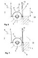
- FIG. 3 Another embodiment of the arrangement of the storage element 8 shows the figure 3.
- the baffle element 8 is fixed to the wire 4.
- it can be a pre-assembly of the storage element 8 take place on the housing of the sieve 4.
- the almost finished unit can then be mounted on site to the intermediate wall 1. This approach reduces the effort on the construction site and thus lowers the assembly costs.
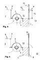
- FIG. 1 Another embodiment of the damming element is shown in FIG.
- the baffle element 8 ' is not rotatably arranged on the intermediate wall 1, but it is arranged vertically displaceable on the outflow side 13.
- the storage element 8 ' can be lowered to change the effective storage area with the hydraulic cylinder 10.
- the upper edge of the baffle element 8 ' is thereby moved in the direction of the top of the intermediate wall 1, whereby the effective height H w is reduced.
- the water from the storage space 10 then flows over the upper edge of the storage element 8 'to the outflow side 13.
- Figure 5 shows the embodiment of Figure 4, wherein the baffle element 8 'is in the cleaning position.
- the effective height H w of the damming element 8 ' is in this state 0.
- Figures 6 and 7 show substantially the same embodiment as is the case with FIGS. 4 and 5.
- the difference is that the damming element 8 'rests on the inflow side 7 is retractable. It may be similar to the embodiment 3, the storage element 8 'on the on the sieve 4 or be attached to the housing of the screening plant. A pre-assembly of the storage element 8 'together with the screw 3 and the wire 4 can hereby be performed.
- the baffle 2 is also on the housing of the sieve, in particular attached to the wire 4. It can as in the illustrated embodiments be made of sheet metal. Of course she can too be concreted and thus the guiding function for guiding the water of the Inflow side 7 through the sieve in the storage space 10 and thus to the discharge side 13 effect.
- the baffle 8 ' are not only lowered into, but can also be brought into a raised position.
- the inflow not over the upper edge of the storage element 8 'but over the lower edge thereof respectively.
- This creates a gap between the top of the partition 1 and the underside of the baffle element 8 ', through which the Water can flow into the discharge side 13.
- the effective height of the damming element 8 'then lies between the water level 12 of the storage space 11th and the lower edge of the baffle element 8 '.
- rotational movements of the storage element 8 are not just about one horizontal axis 9, but also on vertical axes, not shown possible.
- the baffle element 8 is thereby rotated about the vertical axis and opens in two places a gap through which the water from the storage space 11 can flow into the discharge side 13.
Landscapes
- Chemical & Material Sciences (AREA)
- Chemical Kinetics & Catalysis (AREA)
- Health & Medical Sciences (AREA)
- Life Sciences & Earth Sciences (AREA)
- Engineering & Computer Science (AREA)
- Hydrology & Water Resources (AREA)
- Public Health (AREA)
- Water Supply & Treatment (AREA)
- Sewage (AREA)
- Filtration Of Liquid (AREA)
Applications Claiming Priority (2)
| Application Number | Priority Date | Filing Date | Title |
|---|---|---|---|
| DE102004014762 | 2004-03-26 | ||
| DE102004014762A DE102004014762A1 (de) | 2004-03-26 | 2004-03-26 | Abwasseranlage und Verfahren zum Betätigen eines Stauelements einer Abwasseranlage |
Publications (2)
| Publication Number | Publication Date |
|---|---|
| EP1580339A2 true EP1580339A2 (fr) | 2005-09-28 |
| EP1580339A3 EP1580339A3 (fr) | 2006-08-16 |
Family
ID=34854057
Family Applications (1)
| Application Number | Title | Priority Date | Filing Date |
|---|---|---|---|
| EP05101565A Withdrawn EP1580339A3 (fr) | 2004-03-26 | 2005-03-01 | Installation pour eaux usées et méthode pour actionner un barrage de régulation d'une installation pour eaux usées |
Country Status (2)
| Country | Link |
|---|---|
| EP (1) | EP1580339A3 (fr) |
| DE (1) | DE102004014762A1 (fr) |
Cited By (1)
| Publication number | Priority date | Publication date | Assignee | Title |
|---|---|---|---|---|
| DE102018109692A1 (de) | 2018-04-23 | 2019-10-24 | Huber Se | Abtrennung für einen Abwasserkanal sowie Verfahren zur Notentlastung eines Abwasserkanals |
Citations (2)
| Publication number | Priority date | Publication date | Assignee | Title |
|---|---|---|---|---|
| DE3305409A1 (de) | 1983-02-17 | 1984-08-23 | Anton 5788 Winterberg Kanand | Regenabschlagwerk |
| US20040028474A1 (en) | 2000-08-29 | 2004-02-12 | Woodbridge Barrie Christopher | Screen assembly for combined sewer overflow weir |
Family Cites Families (5)
| Publication number | Priority date | Publication date | Assignee | Title |
|---|---|---|---|---|
| CH678281A5 (fr) * | 1988-10-14 | 1991-08-30 | Werner Nill | |
| CH685554A5 (de) * | 1992-09-25 | 1995-08-15 | Romag Roehren & Masch | Abwasseranlage mit eingebauter Siebrecheneinheit. |
| AT400599B (de) * | 1993-04-30 | 1996-01-25 | Nill Werner | Siebrechenanordnung für überlaufbecken |
| ATE209276T1 (de) * | 1996-01-08 | 2001-12-15 | Va Tech Wabag Schweiz Ag | Vorrichtung zum steuerbaren teilen eines zulaufenden flüssigkeitsstroms |
| DE20103875U1 (de) * | 2001-03-07 | 2001-08-16 | Vollmar Gmbh | Abwasseranlage mit Reinigungsvorrichtung |
-
2004
- 2004-03-26 DE DE102004014762A patent/DE102004014762A1/de not_active Withdrawn
-
2005
- 2005-03-01 EP EP05101565A patent/EP1580339A3/fr not_active Withdrawn
Patent Citations (2)
| Publication number | Priority date | Publication date | Assignee | Title |
|---|---|---|---|---|
| DE3305409A1 (de) | 1983-02-17 | 1984-08-23 | Anton 5788 Winterberg Kanand | Regenabschlagwerk |
| US20040028474A1 (en) | 2000-08-29 | 2004-02-12 | Woodbridge Barrie Christopher | Screen assembly for combined sewer overflow weir |
Cited By (1)
| Publication number | Priority date | Publication date | Assignee | Title |
|---|---|---|---|---|
| DE102018109692A1 (de) | 2018-04-23 | 2019-10-24 | Huber Se | Abtrennung für einen Abwasserkanal sowie Verfahren zur Notentlastung eines Abwasserkanals |
Also Published As
| Publication number | Publication date |
|---|---|
| DE102004014762A1 (de) | 2005-10-06 |
| EP1580339A3 (fr) | 2006-08-16 |
Similar Documents
| Publication | Publication Date | Title |
|---|---|---|
| DE69713741T2 (de) | Sediment- und abfallabscheider für regenwasser | |
| DE202009010367U1 (de) | Vorrichtung zur Trennung von Regenwasser von chemisch, biologisch und/oder toxisch belasteten Abwässern | |
| EP1366245B1 (fr) | Installation d'epuration des eaux usees equipee d'un dispositif de purification | |
| DE202008012099U1 (de) | Verbesserter Schmutzwassereinlauf | |
| AT400599B (de) | Siebrechenanordnung für überlaufbecken | |
| DE4139572C2 (de) | Siebanordnung für kreisförmige Regenwasserentlastungsanlagen | |
| DE9308719U1 (de) | Siebrechenanordnung für Regenüberlaufbecken | |
| DE4015414C2 (de) | Überlaufbauwerk mit Rückhaltevorrichtung für Schwimmstoffe in Mischkanalisationen | |
| EP3751067A1 (fr) | Système de dimensionnement de tuyaux | |
| EP0722524B1 (fr) | Systeme de citerne | |
| DE4023557C2 (fr) | ||
| DE4125453A1 (de) | Verfahren und einrichtung zum sammeln und reinigen von regenwasser | |
| DE3510171A1 (de) | Fluessigkeitsrueckhalteeinrichtung fuer den einbau in einen fluessigkeitsspeicherraum | |
| DE202007014331U1 (de) | Schmutzwassereinlauf | |
| EP1580339A2 (fr) | Installation pour eaux usées et méthode pour actionner un barrage de régulation d'une installation pour eaux usées | |
| DE19517101C1 (de) | Vorrichtung zum Entfernen von Abscheidegut aus einer überlaufenden Flüssigkeit | |
| EP0565483B1 (fr) | Bassin dans une installation d'eaux usées | |
| DE19801104C2 (de) | Siebrechen | |
| DE202009016167U1 (de) | Schmutzwassereinlauf mit Sicherung | |
| EP1632619A1 (fr) | Dispositif de commande du débordement dans des installations d'eau | |
| DE10253834A1 (de) | Wasserüberlaufanordnung | |
| DE19919571C2 (de) | Kanalspüler | |
| DE2854209A1 (de) | Vorrichtung zur schwimmschlammraeumung | |
| EP4110497B1 (fr) | Dispositif de soutirage d'eau clarifiée (décanteur) pour installation de clarification | |
| DE9303867U1 (de) | Reinigungsvorrichtung zur Reinigung von in einem Gerinne fließendem Wasser |
Legal Events
| Date | Code | Title | Description |
|---|---|---|---|
| PUAI | Public reference made under article 153(3) epc to a published international application that has entered the european phase |
Free format text: ORIGINAL CODE: 0009012 |
|
| AK | Designated contracting states |
Kind code of ref document: A2 Designated state(s): AT BE BG CH CY CZ DE DK EE ES FI FR GB GR HU IE IS IT LI LT LU MC NL PL PT RO SE SI SK TR |
|
| AX | Request for extension of the european patent |
Extension state: AL BA HR LV MK YU |
|
| PUAL | Search report despatched |
Free format text: ORIGINAL CODE: 0009013 |
|
| AK | Designated contracting states |
Kind code of ref document: A3 Designated state(s): AT BE BG CH CY CZ DE DK EE ES FI FR GB GR HU IE IS IT LI LT LU MC NL PL PT RO SE SI SK TR |
|
| AX | Request for extension of the european patent |
Extension state: AL BA HR LV MK YU |
|
| 17P | Request for examination filed |
Effective date: 20061006 |
|
| AKX | Designation fees paid |
Designated state(s): AT CH DE GB LI |
|
| 17Q | First examination report despatched |
Effective date: 20080220 |
|
| RAP1 | Party data changed (applicant data changed or rights of an application transferred) |
Owner name: HUBER SE |
|
| STAA | Information on the status of an ep patent application or granted ep patent |
Free format text: STATUS: THE APPLICATION IS DEEMED TO BE WITHDRAWN |
|
| 18D | Application deemed to be withdrawn |
Effective date: 20111001 |