EP1580331B1 - Unterwagen für mobile Arbeitsmaschinen - Google Patents
Unterwagen für mobile Arbeitsmaschinen Download PDFInfo
- Publication number
- EP1580331B1 EP1580331B1 EP20050006586 EP05006586A EP1580331B1 EP 1580331 B1 EP1580331 B1 EP 1580331B1 EP 20050006586 EP20050006586 EP 20050006586 EP 05006586 A EP05006586 A EP 05006586A EP 1580331 B1 EP1580331 B1 EP 1580331B1
- Authority
- EP
- European Patent Office
- Prior art keywords
- support
- continuous
- mobile
- mobile unit
- devices
- Prior art date
- Legal status (The legal status is an assumption and is not a legal conclusion. Google has not performed a legal analysis and makes no representation as to the accuracy of the status listed.)
- Expired - Lifetime
Links
Images

Classifications
-
- B—PERFORMING OPERATIONS; TRANSPORTING
- B66—HOISTING; LIFTING; HAULING
- B66C—CRANES; LOAD-ENGAGING ELEMENTS OR DEVICES FOR CRANES, CAPSTANS, WINCHES, OR TACKLES
- B66C23/00—Cranes comprising essentially a beam, boom, or triangular structure acting as a cantilever and mounted for translatory of swinging movements in vertical or horizontal planes or a combination of such movements, e.g. jib-cranes, derricks, tower cranes
- B66C23/62—Constructional features or details
- B66C23/72—Counterweights or supports for balancing lifting couples
- B66C23/78—Supports, e.g. outriggers, for mobile cranes
-
- E—FIXED CONSTRUCTIONS
- E02—HYDRAULIC ENGINEERING; FOUNDATIONS; SOIL SHIFTING
- E02F—DREDGING; SOIL-SHIFTING
- E02F9/00—Component parts of dredgers or soil-shifting machines, not restricted to one of the kinds covered by groups E02F3/00 - E02F7/00
- E02F9/08—Superstructures; Supports for superstructures
- E02F9/085—Ground-engaging fitting for supporting the machines while working, e.g. outriggers, legs
Definitions
- the invention relates to an undercarriage for mobile machines with extendable support devices according to the preamble of claim 1.
- Mobile work machines such as hydraulic excavators, rope excavators and other earthmoving machines or handling equipment usually have an undercarriage, on which the driving devices, for example, the wheels or for example chain drives are arranged. Furthermore, the undercarriage usually has a receiving plate for a slewing ring bearing, on which the superstructure belonging to the revolving stage with slewing gear can be placed.
- This known construction has a large manufacturing effort, in particular due to the extensive components and bearings.
- the track width of the working machine is usually determined by the undercarriage and the chassis hinged thereto.
- a mobile crane with an undercarriage according to the preamble of claim 1 known.
- a mobile on rubber tires wheels crane described with a main frame, the same time the undercarriage forms.
- On the main frame are lowered to a lower support feet provided.
- four support arms are hinged to the main frame, which can be transferred from a folded into an unfolded position.
- the support arms also carry appropriate outriggers.
- the publication FR-A-1 494 349 shows an undercarriage for a crane that can be towed or moved by means of a towing vehicle.
- the chassis in the front and rear area driver devices, wherein in the central region pivotable arms are arranged on the chassis.
- the publication DE 1 209 259 refers to a gantry crane, whose framework consists of two parts interconnected by a hinge joint with field jockey axis, which can be pivoted against each other to change the portal width scissor-like.
- the publication GB 2 135 273 A relates to a mobile crane with a chassis on which a supporting device is rotatably arranged in the region of the front drive wheel.
- the publication DE 34 08 172 A1 relates to a crane having a main frame and ground engaging wheels disposed along the length of the frame on each side thereof for supporting the frame for travel along the ground.
- the publication EP 1 382 560 A1 refers to a vehicle crane whose undercarriage has a central box as a support structure, are formed on the three swing-out support beams.
- Object of the present invention is to develop a generic undercarriage such that bearings and components can be saved and thus a low manufacturing cost, which leads to a minimization of manufacturing costs, is possible.
- an undercarriage for mobile machines is provided with executable support means with a first continuous rigid support on which a part of the support devices is arranged and on which a further continuous support is pivoted articulated carrying the rest of the support means.
- a main drive means is arranged centrally on the first continuous carrier, the first continuous rigid carrier being oriented obliquely to the longitudinal axis of the undercarriage fixed by the main drive means and the further continuous carrier being point symmetrical to a real or imaginary pivot point aligned with the continuous rigid carrier, which also Carrying facilities.
- This new design dissolves from the usual construction concept of the undercarriage, which usually consisted of a complex welded construction with rigidly arranged side members and these interconnecting cross members on which the slewing ring bearings, existed. Characterized in that the support means are arranged directly on the continuous rigid support and on the continuous support connected to it, a direct power flow from the superstructure is made possible in the support means, which is a technical implementation of the tree root principle. This design saves bearing points and components, which on the one hand leads to a lower manufacturing cost and thus to lower production costs.
- variable track width can also be adjusted under load. In desired positions can then be supported by appropriate extension of the support of the entire undercarriage.
- the continuous rigid support may be connected via a rotary joint in the real pivot point with the second continuous rigid support. It can be arranged in the region of the connecting axis between the two carriers, a main driving device, in which case can be arranged on the respective carriers additional Hilfsfahr wornen in the form of support rollers.
- the continuous rigid support is connected to two laterally swingable carriers.
- the carriers can accommodate actively steered wheel sets as driving devices.
- the further continuous carrier can be swung out via drive means, such as piston-cylinder arrangements, threaded spindles or gear.
- the additional continuous carrier can be fixed in its respective position by means of locking means, such as multi-disc brakes or bolts.
- an undercarriage 10 which is a rigidly continuous support 12 which is pivotally connected via a rotary connection not shown here in detail with a second continuous rigid support 14.
- support devices 20 At or after the respective ends of the continuous rigid support 12 and 14 support devices 20 are arranged, which consist essentially of support plates 22, which are on adjusting or 24 retractable.
- the continuous rigid support 12 and 14 which are connected to each other via ball slewing rings, centered on each pivot bearing 26.
- On the turntable bearing 26 of the rigid continuous support 14 can put on the turntable of the upper carriage of the working machine in the usual way. Since these are known constructions, this is not shown in more detail in the drawing.
- a single-wheel drive with individual wheels 18 is arranged.
- the driving stability results from four support rollers 30, which are each arranged on the arms of the rigid support 12 and 14 respectively.
- the undercarriage is shown in a driving position while in Fig. 4 the undercarriage is shown in the working position, in which the rigid support 12 and 14 are pivoted against each other and in a support position. In this case, the rigid support 12 and 14 are pivoted so far that they occupy a nearly right angle to each other.
- the first continuous rigid support 12 is not aligned in the imaginary longitudinal axis of the undercarriage, but obliquely to this, so that here results in an asymmetrical arrangement with respect to a possible axis symmetry imaginary longitudinal axis of the undercarriage.
- the second continuous carrier 14 is arranged point-symmetrical to the first carrier arm 12.
- FIG. 3 A similar symmetry results from the construction of the undercarriage not according to the invention Fig. 3 , This has a likewise asymmetric continuous rigid support 12 on which divided support arms 34 and 36 are each pivotally articulated. A pivoting of the support arms takes place here in manner not shown on adjusting means, which may include drive means such as piston-cylinder assemblies, threaded spindles or gear.
- the split support arms shown here can be fixable in their respective position via locking means, such as multi-disc brakes or in the simplest case bolts (not shown here in detail).
- active wheel sets 32 are arranged on the respective support arms.
Landscapes
- Engineering & Computer Science (AREA)
- Mining & Mineral Resources (AREA)
- Civil Engineering (AREA)
- General Engineering & Computer Science (AREA)
- Structural Engineering (AREA)
- Mechanical Engineering (AREA)
- Vehicle Cleaning, Maintenance, Repair, Refitting, And Outriggers (AREA)
- Jib Cranes (AREA)
- Forklifts And Lifting Vehicles (AREA)
- Non-Deflectable Wheels, Steering Of Trailers, Or Other Steering (AREA)
Description
- Die Erfindung betrifft einen Unterwagen für mobile Arbeitsmaschinen mit ausfahrbaren Abstützeinrichtungen nach dem Oberbegriff des Anspruchs 1.
- Mobile Arbeitsmaschinen, wie beispielsweise Hydraulikbagger, Seilbagger und andere Erdbewegungsmaschinen bzw. Umschlaggeräte haben üblicherweise einen Unterwagen, an welchem die Fahreinrichtungen, beispielsweise also die Räder oder beispielsweise Kettenlaufwerke angeordnet sind. Weiterhin weist der Unterwagen in der Regel eine Aufnahmeplatte für ein Drehkranzlager auf, auf welchem die zum Oberwagen gehörige Drehbühne mit Schwenkwerk aufsetzbar ist. Diese bekannte Konstruktion weist insbesondere aufgrund der umfangreichen Bauteile und Lagerstellen einen großen Fertigungsaufwand auf.
- Im Übrigen ist durch den Unterwagen und die daran angelenkten Fahrwerke die Spurbreite der Arbeitsmaschine in der Regel festgelegt.
- Aus der
DE 34 08 172 C ist ein fahrbarer Kran mit einem Unterwagen gemäß dem Oberbegriff des Anspruchs 1 bekannt. Hier ist ein auf gummibereiften Rädern fahrbarer Kran mit einem Hauptrahmen beschrieben, der gleichzeitig den Unterwagen bildet. Am Hauptrahmen sind zum einen zum Boden absenkbare Abstützfüße vorgesehen. Weiterhin sind vier Stützausleger am Hauptrahmen angelenkt, die von einer angeklappten in eine ausgeklappte Stellung überführbar sind. Auch die Stützausleger tragen entsprechende Abstützfüße. - Die Druckschrift
FR-A-1 494 349 - Die Druckschrift
DE 1 209 259 bezieht sich auf einen Portalkran, dessen Gerüst aus zwei durch ein Drehgelenk mit Lotrichterachse miteinander verbundenen Teilen besteht, welche zur Veränderung der Portalweite scherenartig gegeneinander verschwenkt werden können. - Die Druckschrift
GB 2 135 273 A - Die Druckschrift
DE 34 08 172 A1 betrifft einen Kran mit einem Hauptrahmen und mit dem Boden in Eingriff stehenden Rädern, die über die Länge des Rahmens hinweg auf jeder Seite hiervon zum Tragen des Rahmens für die Fahrt längs des Bodens angeordnet sind. - Die Druckschrift
EP 1 382 560 A1 bezieht sich auf einen Fahrzeugkran dessen Unterwagen einen Zentralkasten als Tragkonstruktion aufweist, an dem drei ausschwenkbare Stützträger ausgebildet sind. - Aufgabe der vorliegenden Erfindung ist es, einen gattungsgemäßen Unterwagen derart weiterzubilden, dass Lagerstellen und Bauteile eingespart werden können und somit ein geringer Fertigungsaufwand, der zu einer Minimierung der Herstellkosten führt, ermöglicht wird.
- Erfindungsgemäß wird diese Aufgabe durch die Kombination der Merkmale des Anspruchs 1 gelöst. Demnach wird ein Unterwagen für mobile Arbeitsmaschinen mit ausführbaren Abstützeinrichtungen mit einem ersten durchgehenden starren Träger ausgestattet, an dem ein Teil der Abstützvorrichtungen angeordnet ist und an dem ein weiterer durchgehender Träger ausschwenkbar angelenkt ist, die die restlichen Abstützeinrichtungen tragen. Erfindungsgemäß ist mittig am ersten durchgehenden Träger eine Hauptfahreinrichtung angeordnet, wobei der erste durchgehende starre Träger schräg zur durch die Hauptfahreinrichtung festgelegte Längsachse des Unterwagens ausgerichtet und der weitere durchgehende Träger ist punktsymmetrisch zu einem realen oder gedachten Schwenkpunkt auf den durchgehenden starren Träger ausgerichtet, wobei dieser ebenfalls Fahreinrichtungen trägt. Diese neue Konstruktion löst sich von dem üblichen Baukonzept des Unterwagens, der in der Regel aus einer komplexen Schweißkonstruktion mit starr zueinander angeordneten Längsträgern und diese miteinander verbindenden Querträgern, auf dem das Drehkranzlager lagert, bestand. Dadurch, dass an dem durchgehenden starren Träger und an dem mit ihm verbundenen durchgehenden Träger unmittelbar die Abstützeinrichtungen angeordnet sind, wird ein direkter Kraftfluss vom Oberwagen in die Abstützeinrichtungen ermöglicht, was eine technische Umsetzung des Baumwurzelprinzips darstellt. Diese Konstruktionsweise spart Lagerstellen und Bauteile ein, was einerseits zu einem geringeren Fertigungsaufwand und damit auch zu geringeren Herstellungskosten führt. Aufgrund der schrägen und damit asymmetrischen Ausrichtungen des ersten Trägers und der entsprechenden punktsymmetrischen Zuordnung des entweder zweiten starren Trägers wobei dieser jeweils ebenfalls Fahreinrichtungen trägt, ist durch Verschwenken der Träger zueinander eine variable Spurbreite möglich. Diese variable Spurbreite kann auch unter Last eingestellt werden. In gewünschten Stellungen kann dann durch entsprechendes Ausfahren der Abstützvorrichtung der gesamte Unterwagen abgestützt werden.
- Bevorzugte Ausgestaltungen der Erfindung ergeben sich aus den sich an den Hauptanspruch anschließenden Unteransprüchen.
- So kann der durchgehende starre Träger über eine Drehverbindung im realen Schwenkpunkt mit dem zweiten durchgehenden starren Träger verbunden sein. Es kann eine Hauptfahreinrichtung im Bereich der Verbindungsachse zwischen den beiden Trägern angeordnet sein, wobei dann an den jeweiligen Trägern zusätzliche Hilfsfahreinrichtungen in Form von Stützrollen angeordnet sein können.
- Gemäß einer alternativen Ausführungsform ist der durchgehende starre Träger mit zwei seitlich ausschwenkbaren Trägern verbunden.
- Vorteilhaft können die Träger als Fahreinrichtungen aktiv gelenkte Radsätze aufnehmen.
- Gemäß einer weiteren vorteilhaften Ausbildung der Erfindung können der weitere durchgehende Träger über Antriebsmittel, wie Kolben-Zylinderanordnungen, Gewindespindeln oder Getriebe ausschwenkbar sein. Der weitere durchgehende Träger Kann über Feststellmittel, wie Lamellenbremsen oder Bolzen, in ihrer jeweiligen Position festlegbar sein.
- Weitere Merkmale, Einzelheiten und Vorteile der Erfindung werden anhand der in der Zeichnung dargestellten Ausführungsbeispiele näher erläutert.
- Es zeigen:
- Fig. 1:
- eine Ausführungsform des erfindungsgemäßen Unterwagens in Fahrstellung,
- Fig. 2:
- Ausführungsform gemäß
Fig. 1 in Arbeitsstellung, - Fig. 3:
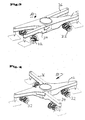
- eine nicht erfindungsgemäße Ausführungsvariante eines Unterwagens in Fahrstellung und
- Fig. 4:
- die Ausführungsvariante gemäß
Fig. 3 in Arbeitsstellung. - In den
Figuren 1 und 2 ist eine erfindungsgemäße Ausführungsvariante eines Unterwagens 10 dargestellt, der einen starr durchgehenden Träger 12, der über eine hier im Detail nicht näher dargestellte Drehverbindung mit einem zweiten durchgehenden starren Träger 14 schwenkbar verbunden ist. An oder nach den jeweiligen Enden der durchgehenden starren Träger 12 und 14 sind Abstützeinrichtungen 20 angeordnet, die im wesentlichen aus Abstützplatten 22 bestehen, die über Verstelleinrichtungen 24 aus- bzw. einfahrbar sind. - Die durchgehenden starren Träger 12 und 14, die über Kugeldrehkränze miteinander verbunden sind, weisen mittig jeweils Drehkranzlager 26 auf. Auf dem Drehkranzlager 26 des starren durchgehenden Trägers 14 kann in üblicher Weise die Drehbühne des Oberwagens der Arbeitsmaschine aufsetzen. Da es sich hier um bekannte Konstruktionen handelt, wird dies nicht näher in der Zeichnung dargestellt.
- Mittels einer weiteren hier nicht näher dargestellten Drehverbindung, die in einer Achse mit der zuvor genannten Drehverbindung angeordnet ist, ist ein Einzelradantrieb mit Einzelrädern 18 angeordnet. Im hier vorliegenden Fall sind nur zwei Einzelräder vorhanden. Die Fahrstabilität ergibt sich durch jeweils vier Stützrollen 30, die jeweils an den Armen der starren Träger 12 bzw. 14 angeordnet sind. In
Fig. 3 ist der Unterwagen in einer Fahrstellung gezeigt, während inFig. 4 der Unterwagen in der Arbeitsstellung dargestellt ist, in der die starren Träger 12 und 14 gegeneinander und in einer Abstützstellung verschwenkt sind. Dabei sind die starren Träger 12 und 14 soweit verschwenkt, dass sie einen nahezu rechten Winkel zueinander einnehmen. - Wie in der
Fig. 1 dargestellt, ist der erste durchgehende starre Träger 12 nicht in der gedachten Längsachse des Unterwagens ausgerichtet, sondern schräg zu dieser, so dass sich hier eine asymmetrische Anordnung bezogen auf eine mögliche Achsensymmetrie gedachten Längsachse des Unterwagens ergibt. Bezüglich des real vorhandenen Drehpunkts inFig. 1 ist der zweite durchgehende Träger 14 punktsymmetrisch zu dem ersten Trägerarm 12 angeordnet. - Eine ähnliche Symmetrie ergibt sich aus der nicht erfindungsgemäßen Konstruktion des Unterwagens entsprechend der
Fig. 3 . Diese weist einen ebenfalls asymmetrischen durchgehenden starren Träger 12 auf, an welchem geteilte Trägerarme 34 und 36 jeweils schwenkbar angelenkt sind. Ein Verschwenken der Trägerarme erfolgt in hier nicht näher dargestellter Art und Weise über Verstelleinrichtungen, wobei diese Antriebsmittel wie Kolben-Zylinderanordnungen, Gewindespindeln oder Getriebe beinhalten können. Die hier dargestellten geteilten Trägerarme können über Feststellmittel, wie Lamellenbremsen oder aber im einfachsten Fall Bolzen (hier im einzelnen auch nicht dargestellt) in ihrer jeweiligen Position festlegbar sein. - Im hier dargestellten Ausführungsbeispiel sind an den jeweiligen Trägerarmen aktive gelenkte Radsätze 32 angeordnet.
Claims (7)
- Unterwagen (10) für mobile Arbeitsmaschinen mit ausfahrbaren Abstützeinrichtungen (20) mit einem ersten durchgehenden starren Träger (12), an dem Fahreinrichtungen (30) und ein Teil der Abstützvorrichtungen (20) angeordnet sind und an dem ein weiterer durchgehender Träger (14) ausschwenkbar angelenkt ist, der die restlichen Abstützeinrichtungen (20) trägt,
dadurch gekennzeichnet,
dass mittig am ersten durchgehenden starren Träger (12) eine Hauptfahreinrichtung (18) angeordnet ist, wobei der erste durchgehende starre Träger (12) schräg zur durch die Hauptfahreinrichtung (18) in Fahrstellung festgelegte Längsachse des Unterwagens ausgerichtet ist und dass der weitere durchgehende Träger (14) punktsymmetrisch zu einem realen Schwenkpunkt auf dem ersten durchgehenden starren Träger (12) ausgerichtet ist, wobei dieser ebenfalls Fahreinrichtungen (30, 32) trägt. - Unterwagen (10) für mobile Arbeitsmaschinen nach Anspruch 1, dadurch gekennzeichnet, dass der erste durchgehende starre Träger (12) über eine Drehverbindung im realen Schwenkpunkt mit dem zweiten durchgehenden starren Träger (14) verbunden ist.
- Unterwagen (10) für mobile Arbeitsmaschinen nach Anspruch 2, dadurch gekennzeichnet, dass die Hauptfahreinrichtung (18) im Bereich der Verbindungsachse zwischen beiden durchgehenden Trägern (12, 14) angeordnet ist.
- Unterwagen (10) für mobile Arbeitsmaschinen nach Anspruch 3, dadurch gekennzeichnet, dass an den jeweiligen durchgehenden Trägern (12, 14) als Fahreinrichtungen Stützrollen (30) angeordnet sind.
- Unterwagen (10) für mobile Arbeitsmaschinen nach einem der Ansprüche 1 - 4, dadurch gekennzeichnet, dass die Träger (12, 14, 34, 36) als Fahreinrichtungen aktiv gelenkte Radsätze (30, 32) aufweisen.
- Unterwagen (10) für mobile Arbeitsmaschinen nach einem der Ansprüche 1 - 5, dadurch gekennzeichnet, dass der weitere durchgehende Träger (14) über Antriebsmittel, wie Kolben-Zylinderanordnungen, Gewindespindeln oder Getriebe, ausschwenkbar ist.
- Unterwagen (10) für mobile Arbeitsmaschinen nach einem der Ansprüche 1 - 6, dadurch gekennzeichnet, dass der weitere durchgehende Träger (14) über Feststellmittel, wie Lamellenbremsen oder Bolzen, in seiner jeweiligen Position festlegbar ist.
Applications Claiming Priority (2)
| Application Number | Priority Date | Filing Date | Title |
|---|---|---|---|
| DE202004004714U | 2004-03-25 | ||
| DE202004004714U DE202004004714U1 (de) | 2004-03-25 | 2004-03-25 | Unterwagen für mobile Arbeitsmaschinen |
Publications (3)
| Publication Number | Publication Date |
|---|---|
| EP1580331A2 EP1580331A2 (de) | 2005-09-28 |
| EP1580331A3 EP1580331A3 (de) | 2006-09-27 |
| EP1580331B1 true EP1580331B1 (de) | 2015-05-20 |
Family
ID=34854228
Family Applications (1)
| Application Number | Title | Priority Date | Filing Date |
|---|---|---|---|
| EP20050006586 Expired - Lifetime EP1580331B1 (de) | 2004-03-25 | 2005-03-24 | Unterwagen für mobile Arbeitsmaschinen |
Country Status (3)
| Country | Link |
|---|---|
| US (2) | US7478835B2 (de) |
| EP (1) | EP1580331B1 (de) |
| DE (1) | DE202004004714U1 (de) |
Families Citing this family (14)
| Publication number | Priority date | Publication date | Assignee | Title |
|---|---|---|---|---|
| US9284168B2 (en) * | 2009-10-01 | 2016-03-15 | Mw Industries, Inc. | Guyless service rig with side-mounted, pivotally deployable rear outriggers |
| US8176665B2 (en) * | 2009-12-28 | 2012-05-15 | Peter Petrovic | Portable target stand for signage |
| EP2466016A1 (de) | 2010-12-14 | 2012-06-20 | Caterpillar, Inc. | Rahmenanordnung und Herstellungsverfahren dafür |
| US8850656B2 (en) * | 2012-06-26 | 2014-10-07 | Luca Buttazzoni | Castor assembly for a modular dolly |
| US8684372B2 (en) * | 2012-06-26 | 2014-04-01 | Luca Buttazzoni | Modular dolly kit |
| US9010798B2 (en) | 2012-07-23 | 2015-04-21 | Luca Buttazzoni | Self-contained dolly assembly |
| US9409585B2 (en) | 2013-07-15 | 2016-08-09 | Luca Buttazzoni | Castor supported dolly assembly capable of being made from lightweight materials and of being used as a pallet assembly |
| US8876145B1 (en) | 2013-07-15 | 2014-11-04 | Luca Buttazzoni | Castor supported dolly assembly capable of being made from lightweight materials and so as to be disposable or severable |
| US8910955B1 (en) | 2013-12-03 | 2014-12-16 | Luca Buttazzoni | Lightweight dolly assembly |
| DE102015226314A1 (de) * | 2015-12-21 | 2017-06-22 | Terex Global Gmbh | Modularer Kran, Transporteinheit für einen modularen Kran und Verfahren zum Betreiben eines derartigen Krans |
| US9868620B1 (en) * | 2016-06-22 | 2018-01-16 | James Alford Flippin | Expandable car jack |
| CN108980546B (zh) * | 2018-08-13 | 2021-03-23 | 李丽莎 | 一种自动调节高度与宽度的电子白板支架 |
| DE102019116809B4 (de) | 2019-06-21 | 2024-11-28 | Hubtex Maschinenbau Gmbh & Co. Kg | Transportfahrzeug, Verfahren zum Aufnehmen einer Last durch ein Transportfahrzeug und System mit einem Transportfahrzeug und einer Last |
| US11535500B1 (en) * | 2021-08-31 | 2022-12-27 | Crossjack Llc | Expandable car jack |
Family Cites Families (15)
| Publication number | Priority date | Publication date | Assignee | Title |
|---|---|---|---|---|
| FR1209259A (fr) | 1958-07-16 | 1960-03-01 | Procédé de fabrication d'un filtre tubulaire à paroi plissée et filtre ainsi obtenu | |
| DE1209259B (de) | 1962-07-24 | 1966-01-20 | Beteiligungs & Patentverw Gmbh | Portalkran |
| FR1494349A (fr) * | 1966-07-19 | 1967-09-08 | Potain & Cie Ets F | Perfectionnements aux châssis de grues à tour remorquables |
| FR1582095A (de) * | 1968-06-07 | 1969-09-26 | ||
| DE2142750A1 (de) * | 1971-08-26 | 1973-04-12 | Krupp Gmbh | Autokran |
| DE2807518C3 (de) * | 1978-02-22 | 1981-09-24 | Habegger, Willy, Hünibach | Radaufhängung für ein Fahr- und Schreitwerk |
| DE2807519C2 (de) * | 1978-02-22 | 1983-10-20 | Habegger, Willy, Hünibach | Fahr- und Schreitwerk |
| US4394913A (en) * | 1980-11-07 | 1983-07-26 | Harnischfeger Corporation | Crane having power operated outriggers and lock means therefor |
| DE3336638C2 (de) * | 1982-10-12 | 1987-04-16 | Fried. Krupp Gmbh, 4300 Essen | Fahrzeugkran hoher Traglast mit verlängerbarem Ausleger, insbesondere Teleskopausleger |
| FR2534237B1 (fr) * | 1982-10-12 | 1987-10-23 | Krupp Gmbh | Grue roulante de grande force portante a fleche extensible, notamment a fleche telescopique |
| FR2541259B1 (fr) | 1983-02-23 | 1986-11-14 | Ppm Sa | Engin mobile, tel qu'une grue mobile, comportant une tourelle et un ensemble de stabilisateurs |
| US4496062A (en) * | 1983-03-07 | 1985-01-29 | Harnischfeger Corporation | Crane having stabilizing outriggers |
| US5029895A (en) * | 1989-07-11 | 1991-07-09 | Schwing America, Inc. | Outrigger-mounted axle assembly |
| EP1008549A3 (de) * | 1998-12-09 | 2000-08-02 | Compact Truck AG | Kranfahrzeug |
| DE10233813A1 (de) | 2002-07-19 | 2004-02-19 | Terex-Demag Gmbh & Co. Kg | Fahrzeugkran mit Radschwenkträgern |
-
2004
- 2004-03-25 DE DE202004004714U patent/DE202004004714U1/de not_active Expired - Lifetime
-
2005
- 2005-03-24 EP EP20050006586 patent/EP1580331B1/de not_active Expired - Lifetime
- 2005-03-25 US US11/089,638 patent/US7478835B2/en not_active Expired - Lifetime
-
2008
- 2008-12-09 US US12/316,103 patent/US20090167008A1/en not_active Abandoned
Also Published As
| Publication number | Publication date |
|---|---|
| EP1580331A3 (de) | 2006-09-27 |
| EP1580331A2 (de) | 2005-09-28 |
| US20050211862A1 (en) | 2005-09-29 |
| DE202004004714U1 (de) | 2005-09-08 |
| US20090167008A1 (en) | 2009-07-02 |
| US7478835B2 (en) | 2009-01-20 |
Similar Documents
| Publication | Publication Date | Title |
|---|---|---|
| EP1580331B1 (de) | Unterwagen für mobile Arbeitsmaschinen | |
| DE3912194C2 (de) | Fahrzeug | |
| DE102016008822B4 (de) | Mobilkran mit verstellbarer Ballastaufnahmevorrichtung | |
| DE102008032739B4 (de) | Mobilkran und Verfahren zur Montage | |
| EP1008549A2 (de) | Kranfahrzeug | |
| EP1925754B1 (de) | Zweiwegebagger | |
| DE29713081U1 (de) | Erntevorsatz mit Stützrädern | |
| EP4232300B1 (de) | Fahrgestell und dessen verwendung | |
| EP1466856A2 (de) | Fahrbarer Kran mit Abstützvorrichtung | |
| DE29613415U1 (de) | Kranfahrzeug | |
| DE2140233B2 (de) | Mehrachsiger fahrzeugkran | |
| EP2886505B1 (de) | Kran | |
| DE102008006119B3 (de) | Mobilkran und Verfahren zur Montage | |
| EP2944166A1 (de) | Fahrwerk einer landwirtschaftlichen maschine | |
| DE2837398A1 (de) | Fahrzeugkran | |
| EP3174779B1 (de) | Schwerlast-transportfahrzeug mit variabler breite | |
| DE4446047A1 (de) | Schleppfahrzeug für Flugzeuge | |
| DE4215599C2 (de) | Kompostwendemaschine | |
| DE102012001377B4 (de) | Ballastwagen für einen Derrickkran | |
| DE9417893U1 (de) | Mähmaschine | |
| DE202008015729U1 (de) | Abstützung für Mobilbagger | |
| DE3814690C2 (de) | Heuwerbungsmaschine mit zum Transport hochklappbaren Arbeitswerkzeugen | |
| DE29719953U1 (de) | Kranfahrzeug | |
| DE1258054B (de) | Schwerlast-Autokran | |
| DE2725042C2 (de) | Bohrwagen für Senkrechtbohrungen |
Legal Events
| Date | Code | Title | Description |
|---|---|---|---|
| PUAI | Public reference made under article 153(3) epc to a published international application that has entered the european phase |
Free format text: ORIGINAL CODE: 0009012 |
|
| AK | Designated contracting states |
Kind code of ref document: A2 Designated state(s): AT BE BG CH CY CZ DE DK EE ES FI FR GB GR HU IE IS IT LI LT LU MC NL PL PT RO SE SI SK TR |
|
| AX | Request for extension of the european patent |
Extension state: AL BA HR LV MK YU |
|
| RIN1 | Information on inventor provided before grant (corrected) |
Inventor name: AUTENRIETH, OLIVER |
|
| PUAL | Search report despatched |
Free format text: ORIGINAL CODE: 0009013 |
|
| AK | Designated contracting states |
Kind code of ref document: A3 Designated state(s): AT BE BG CH CY CZ DE DK EE ES FI FR GB GR HU IE IS IT LI LT LU MC NL PL PT RO SE SI SK TR |
|
| AX | Request for extension of the european patent |
Extension state: AL BA HR LV MK YU |
|
| RIC1 | Information provided on ipc code assigned before grant |
Ipc: E02F 9/08 20060101ALI20060823BHEP Ipc: E02F 9/02 20060101AFI20050706BHEP Ipc: B66C 23/78 20060101ALI20060823BHEP |
|
| 17P | Request for examination filed |
Effective date: 20061025 |
|
| 17Q | First examination report despatched |
Effective date: 20070327 |
|
| AKX | Designation fees paid |
Designated state(s): AT BE BG CH CY CZ DE DK EE ES FI FR GB GR HU IE IS IT LI LT LU MC NL PL PT RO SE SI SK TR |
|
| GRAP | Despatch of communication of intention to grant a patent |
Free format text: ORIGINAL CODE: EPIDOSNIGR1 |
|
| INTG | Intention to grant announced |
Effective date: 20150219 |
|
| RIN1 | Information on inventor provided before grant (corrected) |
Inventor name: AUTENRIETH, OLIVER |
|
| GRAS | Grant fee paid |
Free format text: ORIGINAL CODE: EPIDOSNIGR3 |
|
| GRAA | (expected) grant |
Free format text: ORIGINAL CODE: 0009210 |
|
| AK | Designated contracting states |
Kind code of ref document: B1 Designated state(s): AT BE BG CH CY CZ DE DK EE ES FI FR GB GR HU IE IS IT LI LT LU MC NL PL PT RO SE SI SK TR |
|
| REG | Reference to a national code |
Ref country code: GB Ref legal event code: FG4D Free format text: NOT ENGLISH |
|
| RIN1 | Information on inventor provided before grant (corrected) |
Inventor name: AUTENRIETH, OLIVER |
|
| REG | Reference to a national code |
Ref country code: CH Ref legal event code: EP |
|
| REG | Reference to a national code |
Ref country code: AT Ref legal event code: REF Ref document number: 727832 Country of ref document: AT Kind code of ref document: T Effective date: 20150615 |
|
| REG | Reference to a national code |
Ref country code: IE Ref legal event code: FG4D Free format text: LANGUAGE OF EP DOCUMENT: GERMAN |
|
| REG | Reference to a national code |
Ref country code: DE Ref legal event code: R096 Ref document number: 502005014794 Country of ref document: DE Effective date: 20150625 |
|
| REG | Reference to a national code |
Ref country code: SE Ref legal event code: TRGR |
|
| REG | Reference to a national code |
Ref country code: NL Ref legal event code: T3 |
|
| REG | Reference to a national code |
Ref country code: LT Ref legal event code: MG4D |
|
| PG25 | Lapsed in a contracting state [announced via postgrant information from national office to epo] |
Ref country code: PT Free format text: LAPSE BECAUSE OF FAILURE TO SUBMIT A TRANSLATION OF THE DESCRIPTION OR TO PAY THE FEE WITHIN THE PRESCRIBED TIME-LIMIT Effective date: 20150921 Ref country code: ES Free format text: LAPSE BECAUSE OF FAILURE TO SUBMIT A TRANSLATION OF THE DESCRIPTION OR TO PAY THE FEE WITHIN THE PRESCRIBED TIME-LIMIT Effective date: 20150520 Ref country code: LT Free format text: LAPSE BECAUSE OF FAILURE TO SUBMIT A TRANSLATION OF THE DESCRIPTION OR TO PAY THE FEE WITHIN THE PRESCRIBED TIME-LIMIT Effective date: 20150520 |
|
| PG25 | Lapsed in a contracting state [announced via postgrant information from national office to epo] |
Ref country code: GR Free format text: LAPSE BECAUSE OF FAILURE TO SUBMIT A TRANSLATION OF THE DESCRIPTION OR TO PAY THE FEE WITHIN THE PRESCRIBED TIME-LIMIT Effective date: 20150821 Ref country code: BG Free format text: LAPSE BECAUSE OF FAILURE TO SUBMIT A TRANSLATION OF THE DESCRIPTION OR TO PAY THE FEE WITHIN THE PRESCRIBED TIME-LIMIT Effective date: 20150820 Ref country code: IS Free format text: LAPSE BECAUSE OF FAILURE TO SUBMIT A TRANSLATION OF THE DESCRIPTION OR TO PAY THE FEE WITHIN THE PRESCRIBED TIME-LIMIT Effective date: 20150920 |
|
| PG25 | Lapsed in a contracting state [announced via postgrant information from national office to epo] |
Ref country code: DK Free format text: LAPSE BECAUSE OF FAILURE TO SUBMIT A TRANSLATION OF THE DESCRIPTION OR TO PAY THE FEE WITHIN THE PRESCRIBED TIME-LIMIT Effective date: 20150520 Ref country code: EE Free format text: LAPSE BECAUSE OF FAILURE TO SUBMIT A TRANSLATION OF THE DESCRIPTION OR TO PAY THE FEE WITHIN THE PRESCRIBED TIME-LIMIT Effective date: 20150520 |
|
| REG | Reference to a national code |
Ref country code: DE Ref legal event code: R097 Ref document number: 502005014794 Country of ref document: DE |
|
| PG25 | Lapsed in a contracting state [announced via postgrant information from national office to epo] |
Ref country code: PL Free format text: LAPSE BECAUSE OF FAILURE TO SUBMIT A TRANSLATION OF THE DESCRIPTION OR TO PAY THE FEE WITHIN THE PRESCRIBED TIME-LIMIT Effective date: 20150520 Ref country code: SK Free format text: LAPSE BECAUSE OF FAILURE TO SUBMIT A TRANSLATION OF THE DESCRIPTION OR TO PAY THE FEE WITHIN THE PRESCRIBED TIME-LIMIT Effective date: 20150520 Ref country code: CZ Free format text: LAPSE BECAUSE OF FAILURE TO SUBMIT A TRANSLATION OF THE DESCRIPTION OR TO PAY THE FEE WITHIN THE PRESCRIBED TIME-LIMIT Effective date: 20150520 Ref country code: RO Free format text: LAPSE BECAUSE OF NON-PAYMENT OF DUE FEES Effective date: 20150520 |
|
| PLBE | No opposition filed within time limit |
Free format text: ORIGINAL CODE: 0009261 |
|
| STAA | Information on the status of an ep patent application or granted ep patent |
Free format text: STATUS: NO OPPOSITION FILED WITHIN TIME LIMIT |
|
| REG | Reference to a national code |
Ref country code: FR Ref legal event code: PLFP Year of fee payment: 12 |
|
| 26N | No opposition filed |
Effective date: 20160223 |
|
| PG25 | Lapsed in a contracting state [announced via postgrant information from national office to epo] |
Ref country code: SI Free format text: LAPSE BECAUSE OF FAILURE TO SUBMIT A TRANSLATION OF THE DESCRIPTION OR TO PAY THE FEE WITHIN THE PRESCRIBED TIME-LIMIT Effective date: 20150520 |
|
| PG25 | Lapsed in a contracting state [announced via postgrant information from national office to epo] |
Ref country code: LU Free format text: LAPSE BECAUSE OF FAILURE TO SUBMIT A TRANSLATION OF THE DESCRIPTION OR TO PAY THE FEE WITHIN THE PRESCRIBED TIME-LIMIT Effective date: 20160324 Ref country code: MC Free format text: LAPSE BECAUSE OF FAILURE TO SUBMIT A TRANSLATION OF THE DESCRIPTION OR TO PAY THE FEE WITHIN THE PRESCRIBED TIME-LIMIT Effective date: 20150520 |
|
| REG | Reference to a national code |
Ref country code: CH Ref legal event code: PL |
|
| REG | Reference to a national code |
Ref country code: IE Ref legal event code: MM4A |
|
| PG25 | Lapsed in a contracting state [announced via postgrant information from national office to epo] |
Ref country code: CH Free format text: LAPSE BECAUSE OF NON-PAYMENT OF DUE FEES Effective date: 20160331 Ref country code: LI Free format text: LAPSE BECAUSE OF NON-PAYMENT OF DUE FEES Effective date: 20160331 Ref country code: IE Free format text: LAPSE BECAUSE OF NON-PAYMENT OF DUE FEES Effective date: 20160324 |
|
| REG | Reference to a national code |
Ref country code: FR Ref legal event code: PLFP Year of fee payment: 13 |
|
| REG | Reference to a national code |
Ref country code: AT Ref legal event code: MM01 Ref document number: 727832 Country of ref document: AT Kind code of ref document: T Effective date: 20160324 |
|
| PG25 | Lapsed in a contracting state [announced via postgrant information from national office to epo] |
Ref country code: AT Free format text: LAPSE BECAUSE OF NON-PAYMENT OF DUE FEES Effective date: 20160324 |
|
| REG | Reference to a national code |
Ref country code: FR Ref legal event code: PLFP Year of fee payment: 14 |
|
| PG25 | Lapsed in a contracting state [announced via postgrant information from national office to epo] |
Ref country code: HU Free format text: LAPSE BECAUSE OF FAILURE TO SUBMIT A TRANSLATION OF THE DESCRIPTION OR TO PAY THE FEE WITHIN THE PRESCRIBED TIME-LIMIT; INVALID AB INITIO Effective date: 20050324 Ref country code: CY Free format text: LAPSE BECAUSE OF FAILURE TO SUBMIT A TRANSLATION OF THE DESCRIPTION OR TO PAY THE FEE WITHIN THE PRESCRIBED TIME-LIMIT Effective date: 20150520 |
|
| PG25 | Lapsed in a contracting state [announced via postgrant information from national office to epo] |
Ref country code: TR Free format text: LAPSE BECAUSE OF FAILURE TO SUBMIT A TRANSLATION OF THE DESCRIPTION OR TO PAY THE FEE WITHIN THE PRESCRIBED TIME-LIMIT Effective date: 20150520 |
|
| PGFP | Annual fee paid to national office [announced via postgrant information from national office to epo] |
Ref country code: IT Payment date: 20180330 Year of fee payment: 14 |
|
| PG25 | Lapsed in a contracting state [announced via postgrant information from national office to epo] |
Ref country code: IT Free format text: LAPSE BECAUSE OF NON-PAYMENT OF DUE FEES Effective date: 20190324 |
|
| P01 | Opt-out of the competence of the unified patent court (upc) registered |
Effective date: 20230607 |
|
| PGFP | Annual fee paid to national office [announced via postgrant information from national office to epo] |
Ref country code: NL Payment date: 20240320 Year of fee payment: 20 |
|
| PGFP | Annual fee paid to national office [announced via postgrant information from national office to epo] |
Ref country code: FI Payment date: 20240326 Year of fee payment: 20 Ref country code: GB Payment date: 20240320 Year of fee payment: 20 |
|
| PGFP | Annual fee paid to national office [announced via postgrant information from national office to epo] |
Ref country code: SE Payment date: 20240326 Year of fee payment: 20 Ref country code: FR Payment date: 20240321 Year of fee payment: 20 Ref country code: BE Payment date: 20240320 Year of fee payment: 20 |
|
| PGFP | Annual fee paid to national office [announced via postgrant information from national office to epo] |
Ref country code: DE Payment date: 20240403 Year of fee payment: 20 |
|
| REG | Reference to a national code |
Ref country code: DE Ref legal event code: R071 Ref document number: 502005014794 Country of ref document: DE |
|
| REG | Reference to a national code |
Ref country code: NL Ref legal event code: MK Effective date: 20250323 |
|
| REG | Reference to a national code |
Ref country code: GB Ref legal event code: PE20 Expiry date: 20250323 |
|
| PG25 | Lapsed in a contracting state [announced via postgrant information from national office to epo] |
Ref country code: GB Free format text: LAPSE BECAUSE OF EXPIRATION OF PROTECTION Effective date: 20250323 |
|
| REG | Reference to a national code |
Ref country code: SE Ref legal event code: EUG |
|
| REG | Reference to a national code |
Ref country code: BE Ref legal event code: MK Effective date: 20250324 |