EP1579963B1 - Arc welding robot with umbilical-member managing structure - Google Patents
Arc welding robot with umbilical-member managing structure Download PDFInfo
- Publication number
- EP1579963B1 EP1579963B1 EP05005897A EP05005897A EP1579963B1 EP 1579963 B1 EP1579963 B1 EP 1579963B1 EP 05005897 A EP05005897 A EP 05005897A EP 05005897 A EP05005897 A EP 05005897A EP 1579963 B1 EP1579963 B1 EP 1579963B1
- Authority
- EP
- European Patent Office
- Prior art keywords
- welding
- conduit
- torch
- umbilical
- cable
- Prior art date
- Legal status (The legal status is an assumption and is not a legal conclusion. Google has not performed a legal analysis and makes no representation as to the accuracy of the status listed.)
- Active
Links
Images


Classifications
-
- B—PERFORMING OPERATIONS; TRANSPORTING
- B23—MACHINE TOOLS; METAL-WORKING NOT OTHERWISE PROVIDED FOR
- B23K—SOLDERING OR UNSOLDERING; WELDING; CLADDING OR PLATING BY SOLDERING OR WELDING; CUTTING BY APPLYING HEAT LOCALLY, e.g. FLAME CUTTING; WORKING BY LASER BEAM
- B23K9/00—Arc welding or cutting
- B23K9/24—Features related to electrodes
- B23K9/28—Supporting devices for electrodes
- B23K9/287—Supporting devices for electrode holders
Definitions
- the present invention relates to an arc welding robot including an umbilical member managing structure for a welding torch according to the preamble part of claim 1.
- Such a welding robot is known from JP-A-03 066 267 .
- a configuration has been known in which a welding torch is attached to the distal end of a forearm of the robot, and a wire feeding device is provided on the forearm so as to feed a welding wire, through a torch cable, to the welding torch.
- Fig. 1A is a front view schematically showing the configuration of this type of arc welding robot
- Fig. 1B is a side view showing a portion around the welding torch of the arc welding robot as seen from the left side of Fig. 1A . As shown in Fig.
- a welding torch 2 is attached to the distal end of an arm (or a forearm) of a robot mechanical section 1, and a wire feeding device 4 is mounted on a support base 5 of the robot arm (forearm).
- a torch cable 3 is laid between the wire feeding device 4 and the welding torch 2.
- the torch cable 3 contains a plurality of umbilical members such as a gas pipe, an electric wire, etc. for feeding them.
- the welding wire is fed to be passed through a tubular welding-wire liner, and the assist gas is supplied to flow in a tube.
- the assist gas is supplied to flow in a tube.
- several linear electrical conductors are used for supplying the welding current.
- the torch cable 3 containing various umbilical members is subjected to a large load as the robot mechanical section 1 operates.
- a wrist axis of the robot mechanical section performs an orientation change (i.e., a turning) of the welding torch 2
- the posture of the torch cable 3 changes to a large extent, as shown by broken lines 3a, 3b in Fig. 1B , due to the turning motion of the welding torch 2 (see broken lines 2a, 2b), so that the torch cable 3 is subjected to a bending or twisting action.
- a cable structure i.e., an umbilical-member managing structure
- JP 2003-230963 A JP 2003-230963 A , WO-A-03 066 267 .
- a tubular liner i.e., a conduit liner
- the liner 6 is accommodated within a gas hose 8 for flowing an assist gas therethrough, and two or more (typically several) electrical conductors 9 are disposed on the outside of the gas hose 8.
- the electrical conductors 9 are arranged side-by-side along the outer circumference of the gas hose 8 so as to be spaced from each other, and a retainer tape 10 is wound around them from the outside thereof. Then, a sheath 11 is provided outside the retainer tape 10.
- the plural electrical conductors 9 are arranged to be spaced from each other, so that, when a deformation such as bending or twisting is generated in the torch cable 3, the electrical conductors 9 can individually move in a direction as to avoid the deformation such as bending or twisting. Therefore, the fatigue of the electrical conductors 9 due to deformation can be reduced.
- a conventional torch cable has a structure, as does the cable structure as described above, in which a plurality of umbilical members, including a liner used for a welding wire, a tube for feeding an assist gas and plural electrical conductors for feeding a welding current, are contained together within a single cable having an outer diameter reduced to as small as possible, for the purpose of reducing a material cost and a radial dimension.
- the torch cable has a significantly low flexibility.
- the low flexibility of the torch cable gives an unfavorable result in a case where it is used in an arc welding robot having a wire feeding device mounted on a forearm.
- a welding torch moves freely as a wrist section operates, so that a torch cable is repeatedly subjected to bending or twisting. Therefore, if the torch cable with low flexibility is used, it is difficult to prevent premature cable breakage even when the torch cable has the cable structure as shown in Fig. 2 .
- a reduced length and a reduced radius of curvature are provided for a portion of the torch cable between the wire feeding device and the welding torch, so that a stress exerted upon the torch cable, due to bending or twisting, becomes large and this may shorten the life of the torch cable.
- US-A-2001 052 564 is directed to a cable guidance hose having a rotatable connection mechanism.
- the present invention provides an arc welding robot including an umbilical-member managing structure for a welding torch provided, for laying and managing, along a manipulator, a plurality of umbilical members connected to a welding torch attached to the manipulator with the features of claim 1.
- the plurality of umbilical members include a welding wire to be fed to the welding torch, a tubular liner surrounding the welding wire, a tube for supplying an assist gas to the welding torch, and a plurality of electrical conductors for feeding a welding current to the welding torch; wherein the arc welding robot is provided with a wire feeding device mounted on the manipulator for feeding the welding wire to the welding torch; and wherein the umbilical-member managing structure comprises a flexible conduit containing the plurality of umbilical members, the flexible conduit including a first connecting section provided at one longitudinal end to be connected to the welding torch, and a second connecting section provided at another longitudinal end to be connected to the wire feeding device; and a connection mechanism provided for at least one of the first and second connecting sections of the conduit, the connection mechanism connecting the conduit in a rotatable manner to at least one of the welding torch and the wire feeding device.
- the conduit contains the electrical conductors integrated into a multi-core cable separated from both of the tubular liner for welding wire and the tube for assist gas.
- the above umbilical-member managing structure may further comprise a clamp mechanism provided in association with at least one of the first and second connecting sections of the conduit, the clamp mechanism clamping the plurality of umbilical members relative to at least one of the welding torch and the wire feeding device.
- the above umbilical-member managing structure may further comprise a retaining member provided in an interior of the conduit, the retaining member retaining the plurality of umbilical members at a predetermined position.
- Figs. 3A and 3B respectively show, as front and side views, the entire configuration of an industrial arc welding robot, in which an umbilical-member managing structure 20 for a welding torch, according to an embodiment of the present invention, is used.
- the illustrated arc welding robot includes a mechanical section 22 having six degrees of freedom, and a robot controller 24 for controlling the axes of the mechanical section 22.
- the mechanical section 22 includes a robot arm or manipulator 26 having a wrist (as described later), and a welding torch 28 is attached, as a working tool (i.e., an end effector), to the wrist of the manipulator 26.
- the mechanical section 22 operates to shift the welding torch 28 attached to the distal end of the wrist to a target position while keeping a designated orientation, in accordance with a command issued from the robot controller 24, so as to make the welding torch follow a join in an object to be welded.
- servo-motors (not shown), provided for the six axes of the mechanical section 22, are connected to and controlled by the robot controller 24 through a control cable (not shown).
- the umbilical-member managing structure for a welding torch may be applied, not only to the illustrated vertically articulated robot having a six-axes configuration, but also to a vertically articulated robot having another configuration such as a five-axes configuration.
- the arc welding robot as illustrated further includes a welding power supply 30 for carrying out a welding operation by the welding torch 28.
- the robot controller 24 also issues a welding command to the welding power supply 30 simultaneously with an operation command to the servo-motor of each axis of the mechanical section 22.
- the welding power supply 30 is connected through a feeder cable 32 to a wire feeding device 34 provided on the manipulator 26.
- the wire feeding device 34 supports a torch cable 36 connected to the welding torch 28 on the manipulator 26, and operates to feed a welding wire 38 delivered from a not-shown welding-wire drum toward the welding torch 28 through the torch cable 36.
- the feeder cable 32 is introduced to the interior of the torch cable 36 at the wire feeding device 34, and is electrically connected to the welding wire 38 at the interior of the welding torch 28.
- the welding power supply 30 applies welding voltage and welding current, under the control of the robot controller 24 synchronously with the operation of the mechanical section 22, through the feeder cable 32 to the welding wire 38 dispensed from the distal end of the welding torch 28.
- the manipulator 26 includes a forearm (or a forearm base) 40 having a longitudinal first axis ⁇ , a first wrist element 42 joined to the forearm 40 rotatably about the first axis ⁇ , and a second wrist element 44 joined to the first wrist element 42 rotatably about a second axis ⁇ extending in a direction generally perpendicular to the first axis ⁇ .
- the welding torch 28 is attached through an attachment member 46 to the second wrist element 44 at a position somewhat spaced from the second axis ⁇ and opposite to the forearm 40.
- a mounting substrate 48 is formed on the forearm 40, and the wire feeding device 34 is mounted on the mounting substrate 48. In this connection, depending upon the configuration of a robot (or a mechanical section), a manipulator including a forearm and a wrist element and having a different joint configuration may be provided.
- the umbilical-member managing structure 20 for a welding torch serves for laying and managing, along the manipulator 26, a plurality of umbilical members connected to the welding torch 28 attached to the manipulator 26.
- the umbilical members includes a welding wire 38 to be fed to the welding torch 28, a tubular liner 50 surrounding the welding wire 38, a tube 52 for supplying an assist gas to the welding torch 28, and an electrical conductor 54 for feeding a welding current to the welding torch 28, all of which are contained in the torch cable 36 (see Fig. 4 ). Therefore, the torch cable 36 provides not only a feeding passage for the welding wire 38 but also passages for feeding the assist gas and the welding current.
- the torch cable 36 may be subjected to a twisting action.
- the umbilical-member managing structure 20 employs the torch cable 36 having a cross-sectional structure as shown in Fig. 4 , and also uses a connection structure provided for at least one of a first end section 36a at the side of the welding torch 28 and a second end section 36b at the side of the wire feeding device 34, to establish a rotatable support of the torch cable 36 about the longitudinal axis thereof, as will be described later.
- a cable guide 56 is provided, as occasion demands, at one or more locations on the manipulator 36, the cable guide 56 movably retaining a portion of the torch cable 36 in the longitudinal and rotational directions thereof.
- the cable guide 56 for stabilizing the behavior of the torch cable 36 is provided at a suitable location on the manipulator 26, it is possible to predict the behavior of the torch cable 36, and thus to prevent the torch cable 36 from showing an unstable and unpredictable behavior.
- the torch cable 36 constituting the umbilical-member managing structure 20 has a structure in which a tubular liner (or a conduit liner) 50 used as a passage for the welding wire 38, a tube (or a gas hose) 52 for supplying assist gas, and a multi-core cable 58 for operation use, formed by bundling a plurality of electrical conductors 54, are contained in a flexible conduit 60.
- Material for the conduit 60 may be selected suitably, for example, from various flexible resinous materials.
- the torch cable is wound around or otherwise is rearranged along the manipulator 26 ( Fig.
- a stress generated in the conduit 60 is significantly reduced by adopting a tension reduction technique or a terminating rotatable connection mechanism as described later, so that it is not difficult to select a material having a practically sufficient durability.
- the tubular liner 50 surrounding the welding wire 38 is inserted into the interior of the tube 52 and is arranged substantially along the longitudinal axis of the conduit 60.
- a double or nested tube comprised of the tubular liner 50 and the tube 52 is disposed with a center line thereof substantially coinciding with the longitudinal axis of the conduit 60.
- the length of the tube 52 for the assist gas is set to be shorter than the other umbilical members in the conduit 60, so that the tube 52 is first, among the components of the torch cable 36, subjected to the bending or twisting action. With this configuration, it is possible to avoid the tension due to the bending or twisting action to be directly applied to the conduit 60.
- the multi-core cable 58 for operation use formed by bundling the plural electrical conductors 54, is inserted into and contained in the conduit 60 in a manner as to be separated from the tube 52 through which the tubular liner 50 is passed.
- the tube 52 and the multi-core cable 58 do not constitute an umbilical-member assembly in which umbilical members are integrated into a single unit as in the conventional structure as shown in Fig. 2 .
- the multi-core cable 58 is disposed so as to extend at an eccentric position deviated from the longitudinal axis of the conduit 60 by a predetermined distance.
- an umbilical member formed by incorporating the tubular liner 50 surrounding the welding wire 38 into the tube 52 for supplying assist gas, and another umbilical member comprised of the multi-core cable 58 for operation use formed by bundling the electrical conductors 54 for feeding welding current, are separately and individually inserted into the conduit tube 60, so that it is possible to reduce the diameter of each umbilical member. It is also possible to sufficiently reduce the outer diameter of the double or nested tube comprised of the tubular liner 50 and the tube 52, provided that a very thin welding wire is fed smoothly and that the flow of assist gas is not impeded.
- the multi-core cable 58 for operation use by bundling a large number of thin electrical conductors 54, and thus to easily reduce the outer diameter of the multi-core cable 58 without losing its flexibility. In this manner, it is possible to effectively reduce the stress generated due to the bending or twisting action of the torch cable 36 during the operation of the robot (in particular, the wrist thereof), and thus to improve the life span of the torch cable 36.
- the multi-core cable 58 may be wound helically around the assist-gas tube 52.
- each umbilical member it is possible to reduce the diameter of each umbilical member, and thus to ensure a sufficient internal space 62 of the conduit 60 without significantly decreasing the diameter of the conduit 60.
- each of the umbilical members can move in the interior of the conduit 60, they are covered by the conduit 60 and thereby suitably confined, so that it is possible to somewhat reduce the interference between the umbilical members and the surrounding objects.
- the tubular liner 50 as an umbilical member for feeding the welding wire 38, is required to undergo a regular maintenance procedure, because the inner wall surface of the liner is worn by the passage of the welding wire 38 after being used for a long time.
- the tubular liner 50 for the welding wire 38 is separated from the operation-use multi-core cable 58, formed by bundling the welding-current electrical conductors 54, and is disposed in the conduit 60 as a separate umbilical member, so that, in the maintenance procedure of the tubular liner 50, it is required to replace only the tubular liner 50 surrounding the welding wire 38, which can reduce the maintenance cost and an operational load.
- the plural electrical conductors 54 are integrated into a single multi-core cable 58
- two or more multi-core cables for operation use may be formed by grouping the plural electrical conductors 54.
- it is possible to further improve the life of the cable by providing a plurality of stranded electrical conductors including a plurality of very fine wires and forming a multi-core cable by further bundling in a strand fashion the plural stranded electrical conductors.
- a support structure rotatable about a longitudinal axis which is provided for at least one of the end section 36a of the torch cable 36 at the side of the welding torch 28 (i.e., a first connecting section 60a of the conduit 60) and the end section 36b of the torch cable 36 at the side of the wire feeding device 34 (i.e., a second connecting section 60b of the conduit 60), will be described below.
- rotatable support structures are provided for both end sections 36a, 36b of the torch cable 36. If the rotatable support structure is provided only for either one of the end sections, the torch cable 36 is fixed at the other end section to the welding torch 28 or to the wire feeding device 34.
- Figs. 5A and 5B show a conduit connection mechanism 64 provided for the end section 36a ( Fig. 3A ) of the torch cable 36 at the side of the welding torch 28.
- the conduit connection mechanism 64 includes a cylindrical cable holder 66 attached to the first connecting section 60a at one longitudinal end of the conduit 60.
- the cable holder 66 is provided at one longitudinal end thereof with a flange 66a having screw holes, and the flange 66a is detachably fastened to a flange member 68 provided at the first connecting section 60a of the conduit 60 using fastening screws 70.
- a bearing unit 72 having rolling elements 72a is provided on the outer circumference of the cable holder, and a holder 74 provided on the welding torch 28 is rotatably attached through the bearing unit 72 to the cable holder 66.
- the welding torch 28 and the conduit 60 are disposed in a concentric correlation.
- the conduit 60 is connected through the holders 66, 74 to the welding torch 28 in a condition rotatable about the longitudinal axis of the conduit 60.
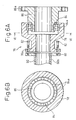
- Figs. 6A and 6B show a conduit connection mechanism 76 provided for the end section 36b ( Fig. 3A ) of the torch cable 36 at the side of the wire feeding device 34.
- the conduit connection mechanism 76 has generally the same configuration as the above-described conduit connection mechanism 64, and includes a cylindrical cable holder 78 attached to the second connecting section 60b at another longitudinal end of the conduit 60.
- the cable holder 78 is provided at one longitudinal end thereof with a flange 78a having screw holes, and the flange 78a is detachably fastened to a flange member 80 provided at the second connecting section 60b of the conduit 60 using fastening screws 82.
- a bearing unit 84 having rolling elements 84a is provided on the inner circumference of the cable holder.
- a holder 86 provided on the wire feeding device 34 ( Fig. 3A ) is rotatably attached through the bearing unit 84 to the cable holder 78.
- the holder 86 of the wire feeding device 34 and the conduit 60 are disposed in a concentric correlation.
- the holder 86 is attached to the body (not shown) of the wire feeding device 34 using a flange 86a provided at the end opposite to the bearing unit 84.
- the conduit 60 is connected through the holders 78, 86 to the wire feeding device 34 in a condition rotatable about the longitudinal axis of the conduit 60.
- the umbilical-member managing structure 20 having the above-described configuration may further include a clamp mechanism for clamping the plural umbilical members in the conduit 60 relative to the welding torch 28 and/or the wire feeding device 34.
- a clamp mechanism may be provided in association with at least one of the first connecting section 60a and the second connecting section 60b of the conduit 60.
- Fig. 7 shows, by way of example, a clamp mechanism 88 provided at a location where the operation-use multi-core cable 58 for supplying welding current is connected to the welding torch 28. It is preferred that the multi-core cable 58 is also clamped in the same manner at a location where the multi-core cable 58 is connected to the wire feeding device 34. The sheath of the multi-core cable is stripped at opposite ends thereof where the multi-core cable 58 is connected to the welding torch 28 and to the wire feeding device 34, and the electrical conductors 54 arranged inside are connected to a counterpart member through a caulking or by using a connecting member such as a press-fitting terminal. In the example shown in Fig.
- the sheath 58a is partially removed at one end of the multi-core cable 58, corresponding to the first connecting section 60a of the conduit 60, and the portions of the electrical conductors 54 exposed therefrom are connected to a wire press-fitting terminal 92 provided on a connecting member 90 formed on the welding torch 28 ( Fig. 3A ).
- the clamp mechanism 88 includes a clamp plate 96 adapted to be fixed to the connecting member 90 using fastening bolts 94 and a desired number (two, in the figure) of bands 98 for holding an end length of the multi-core cable 58, which has the sheath 58a, onto the clamp plate 96 in an adjacent fashion.
- the operation-use multi-core cable 58 is disposed at the eccentric position deviated from the center of the conduit 60, and the assist-gas tube 52 passes adjacent to the center of the conduit 60.
- the assist-gas tube 52 is connected to a tube connecting section 100 formed on the connecting member 90.
- an assist-gas passage (not shown) is formed to extend from the tube connecting section 100 to the welding torch 23 ( Fig. 3A ).
- the provision of the clamp mechanisms for clamping the outer circumferences of the umbilical members to the counterpart connecting member at a location where the respective umbilical members passing through the conduit 60 are connected to the welding torch 28 or to the wire feeding device 34, makes it possible to reduce the influence of an external force exerted upon the umbilical members, and thus to effectually increase the life span of the umbilical members.
- the umbilical-member managing structure 20 having the above configuration further includes a retaining member 102 arranged at a suitable location in the interior of the conduit 60 for retaining the plural umbilical members at a predetermined position.
- Figs. 8A and 8B show, by way of example, the retaining member 102 incorporated in the structure shown in Fig. 7 .
- the retaining member 102 is a disc-shaped member having a suitable thickness with the outer diameter thereof being slightly smaller than the inner diameter of the conduit 60, and is provided with a plurality of through-holes 104, 106 for holding and guiding the umbilical members.
- the through-holes 104, 106 are formed at positions corresponding to those occupied by the objective umbilical members in a normal or non-stressed condition in the conduit 60.
- the through-hole 104 formed at the center of the retaining member 102 holds and guides the assist-gas tube 52
- the through-hole 106 formed at an eccentric position deviated from the center holds and guides the sheath 58a of the operation-use multi-core cable 58.
- These through-holes are formed such that the inner diameter of the through-hole 104 is slightly larger than the outer diameter of the assist-gas tube 52, and the inner diameter of the through-hole 106 is slightly larger than the outer diameter of the sheath 58a of the multi-core cable 58.
- the tubular liner 50 providing a passage for the welding wire 38 is contained in the assist-gas tube 52, so that it is very desirable for ensuring a feeding stability of the welding wire 38 that the assist-gas tube 52 is retained to be substantially aligned with the longitudinal axis of the conduit 60 in this manner.
- the retaining member 102 acts to prevent the "fluttering" of the assist-gas tube 52 in the conduit 60, which further improves the feeding stability of the welding wire 38.
- a nylon band 108 is wound around the assist-gas tube 52 near the opposite opening ends of the through-hole 104, so as to suppress the fluctuation of the retaining member 102 in the longitudinal direction of the conduit 60.
- a material having a self-lubricating property e.g., Teflon®
- Teflon® a material having a self-lubricating property
- the flexible conduit is used for containing the welding-wire liner, the assist-gas tube and the welding-current electrical conductors, and a rotational degree of freedom about the longitudinal axis of the conduit is ensured for at least one end of the conduit, so that it is possible to easily eliminate a stress generating due to the bending and twisting action of the conduit, during the operation of the manipulator (in particular, the turning operation of the welding torch).
- the welding-current electrical conductors are disposed in the conduit in a condition as to be separated from the welding-wire liner and the assist-gas tube, so that the mutual influence between the motion of the electrical conductors and the motion of the welding-wire liner and assist-gas tube is substantially eliminated and, therefore, the stress due to the bending and twisting action can be reduced.
- the welding-current conductors are broken and/or the welding wire liner is worn and damaged, it is required to replace only one of these umbilical members, which makes the cost of maintenance lower.
- a torch cable containing a plurality of umbilical members such as a welding-wire liner, an assist-gas tube and welding-current electrical conductors
Landscapes
- Engineering & Computer Science (AREA)
- Physics & Mathematics (AREA)
- Plasma & Fusion (AREA)
- Mechanical Engineering (AREA)
- Manipulator (AREA)
- Arc Welding In General (AREA)
Applications Claiming Priority (2)
| Application Number | Priority Date | Filing Date | Title |
|---|---|---|---|
| JP2004084917A JP4301984B2 (ja) | 2004-03-23 | 2004-03-23 | アーク溶接ロボットの溶接トーチ用線条体処理構造 |
| JP2004084917 | 2004-03-23 |
Publications (2)
| Publication Number | Publication Date |
|---|---|
| EP1579963A1 EP1579963A1 (en) | 2005-09-28 |
| EP1579963B1 true EP1579963B1 (en) | 2008-03-26 |
Family
ID=34858402
Family Applications (1)
| Application Number | Title | Priority Date | Filing Date |
|---|---|---|---|
| EP05005897A Active EP1579963B1 (en) | 2004-03-23 | 2005-03-17 | Arc welding robot with umbilical-member managing structure |
Country Status (5)
| Country | Link |
|---|---|
| US (1) | US7196285B2 (zh) |
| EP (1) | EP1579963B1 (zh) |
| JP (1) | JP4301984B2 (zh) |
| CN (1) | CN100374235C (zh) |
| DE (1) | DE602005005537T2 (zh) |
Families Citing this family (17)
| Publication number | Priority date | Publication date | Assignee | Title |
|---|---|---|---|---|
| JP4168008B2 (ja) * | 2004-06-04 | 2008-10-22 | ファナック株式会社 | 産業用ロボットの線条体処理構造 |
| JP4233503B2 (ja) * | 2004-09-06 | 2009-03-04 | ファナック株式会社 | アーク溶接ロボットのトーチケーブル処理構造 |
| JP4261598B2 (ja) | 2007-07-30 | 2009-04-30 | ファナック株式会社 | 産業用ロボットの線条体処理構造 |
| DE102008019327B4 (de) * | 2008-04-16 | 2011-12-01 | Tbi Industries Gmbh | Schlauchpaketanordnung |
| US8987637B1 (en) * | 2010-10-21 | 2015-03-24 | The Reliable Automatic Sprinkler Co, Inc. | Welding torch oscillator with motorized pitch control |
| CN102452079A (zh) * | 2010-10-27 | 2012-05-16 | 鸿富锦精密工业(深圳)有限公司 | 机器人臂部件 |
| AU2013209396B2 (en) * | 2012-01-19 | 2016-07-07 | Victor Equipment Company | Universal conduit assembly for a welding torch |
| JP6211343B2 (ja) * | 2013-08-09 | 2017-10-11 | ヤマハ発動機株式会社 | ロボットアームの配線構造 |
| EP2835226A1 (en) * | 2013-08-09 | 2015-02-11 | Yamaha Hatsudoki Kabushiki Kaisha | Wiring structure for robot arm |
| JP6407736B2 (ja) | 2015-01-14 | 2018-10-17 | ファナック株式会社 | 産業用ロボットに実装される複合ケーブル |
| CN105058426B (zh) * | 2015-08-18 | 2017-06-13 | 埃夫特智能装备股份有限公司 | 工业机器人用外围管线安装旋转底座及其装配方法 |
| JP6441255B2 (ja) | 2016-04-07 | 2018-12-19 | ファナック株式会社 | ロボットの線条体処理構造 |
| KR101858536B1 (ko) * | 2016-06-09 | 2018-05-17 | 대우조선해양 주식회사 | 로봇용 용접토치 |
| KR101875281B1 (ko) * | 2016-09-07 | 2018-07-05 | 김오갑 | 서브머지드 아크 용접용 플럭스 회수호스 지지장치 |
| KR101875787B1 (ko) * | 2016-09-12 | 2018-07-06 | 대우조선해양 주식회사 | 협소공간 용접을 위한 로봇용 착탈식 회전용접토치 |
| US10603738B2 (en) * | 2016-11-14 | 2020-03-31 | Electron Beam Technologies, Inc. | Cable for arc welder |
| CN115515765A (zh) * | 2020-05-21 | 2022-12-23 | 发那科株式会社 | 工业用机器人 |
Family Cites Families (4)
| Publication number | Priority date | Publication date | Assignee | Title |
|---|---|---|---|---|
| JPH0528563A (ja) | 1991-07-18 | 1993-02-05 | Nec Corp | 光磁気記録再生方法 |
| EP1163986B1 (de) * | 2000-06-15 | 2008-03-12 | KUKA Roboter GmbH | Vorrichtung zum Festlegen eines Kabelführungsschlauchs |
| DE10141407A1 (de) * | 2001-04-19 | 2002-10-31 | Ernst & Engbring Gmbh & Co Kg | Vorrichtung zum Halten eines Leitungsbündels bei einem Roboter |
| JP4001224B2 (ja) | 2002-02-08 | 2007-10-31 | 株式会社安川電機 | アーク溶接ケーブル |
-
2004
- 2004-03-23 JP JP2004084917A patent/JP4301984B2/ja not_active Expired - Lifetime
-
2005
- 2005-03-17 EP EP05005897A patent/EP1579963B1/en active Active
- 2005-03-17 DE DE602005005537T patent/DE602005005537T2/de active Active
- 2005-03-22 US US11/085,036 patent/US7196285B2/en active Active
- 2005-03-23 CN CNB2005100569102A patent/CN100374235C/zh active Active
Also Published As
| Publication number | Publication date |
|---|---|
| CN100374235C (zh) | 2008-03-12 |
| US7196285B2 (en) | 2007-03-27 |
| US20050211686A1 (en) | 2005-09-29 |
| JP2005271003A (ja) | 2005-10-06 |
| EP1579963A1 (en) | 2005-09-28 |
| CN1672853A (zh) | 2005-09-28 |
| JP4301984B2 (ja) | 2009-07-22 |
| DE602005005537T2 (de) | 2009-04-16 |
| DE602005005537D1 (de) | 2008-05-08 |
Similar Documents
| Publication | Publication Date | Title |
|---|---|---|
| EP1579963B1 (en) | Arc welding robot with umbilical-member managing structure | |
| US7202442B2 (en) | Cable arrangement for robot arm, and industrial robot utilizing the same | |
| EP1611988B1 (en) | Arc-welding robot with a torch cable disposition structure | |
| US6795750B2 (en) | Industrial robot | |
| EP1632304B1 (en) | Arc welding robot attached to a ceiling or a wall including treating torch cable structure | |
| US20060104791A1 (en) | Umbilical member managing system for industrial robot | |
| JP4280295B2 (ja) | 産業用ロボット | |
| EP1743748B1 (en) | Guiding structure comprising a flexible tabular guide member for an umbilical member of an industrial robot | |
| US20060101936A1 (en) | Managing structure for umbilical member of industrial robot | |
| EP1892064A1 (en) | Drive mechanism for industrial robot arm | |
| US20050103148A1 (en) | Cable distribution and support equipment for sensor in robot system | |
| JP2008238320A (ja) | 作業ツールを備えたロボット | |
| CN110311344B (zh) | 电缆夹以及机器人 | |
| US5694813A (en) | Industrial robot | |
| US6455799B1 (en) | Robot device | |
| JP4628758B2 (ja) | 溶接用ロボット | |
| JP2006281226A (ja) | ワイヤ送給装置 | |
| CA3075293C (en) | Welding cable assembly, welding torch assembly, and robotic welding systems, with a spring mechanically coupled to the cable | |
| JPH04269193A (ja) | 産業用ロボツト | |
| JPH04269192A (ja) | 産業用ロボツト | |
| JP2010075948A (ja) | コンジットケーブル |
Legal Events
| Date | Code | Title | Description |
|---|---|---|---|
| PUAI | Public reference made under article 153(3) epc to a published international application that has entered the european phase |
Free format text: ORIGINAL CODE: 0009012 |
|
| AK | Designated contracting states |
Kind code of ref document: A1 Designated state(s): AT BE BG CH CY CZ DE DK EE ES FI FR GB GR HU IE IS IT LI LT LU MC NL PL PT RO SE SI SK TR |
|
| AX | Request for extension of the european patent |
Extension state: AL BA HR LV MK YU |
|
| 17P | Request for examination filed |
Effective date: 20050915 |
|
| AKX | Designation fees paid |
Designated state(s): DE |
|
| 17Q | First examination report despatched |
Effective date: 20060623 |
|
| GRAP | Despatch of communication of intention to grant a patent |
Free format text: ORIGINAL CODE: EPIDOSNIGR1 |
|
| GRAS | Grant fee paid |
Free format text: ORIGINAL CODE: EPIDOSNIGR3 |
|
| GRAA | (expected) grant |
Free format text: ORIGINAL CODE: 0009210 |
|
| AK | Designated contracting states |
Kind code of ref document: B1 Designated state(s): DE |
|
| REF | Corresponds to: |
Ref document number: 602005005537 Country of ref document: DE Date of ref document: 20080508 Kind code of ref document: P |
|
| PLBE | No opposition filed within time limit |
Free format text: ORIGINAL CODE: 0009261 |
|
| STAA | Information on the status of an ep patent application or granted ep patent |
Free format text: STATUS: NO OPPOSITION FILED WITHIN TIME LIMIT |
|
| 26N | No opposition filed |
Effective date: 20081230 |
|
| REG | Reference to a national code |
Ref country code: DE Ref legal event code: R082 Ref document number: 602005005537 Country of ref document: DE Representative=s name: WUESTHOFF & WUESTHOFF PATENT- UND RECHTSANWAEL, DE |
|
| REG | Reference to a national code |
Ref country code: DE Ref legal event code: R081 Ref document number: 602005005537 Country of ref document: DE Owner name: FANUC CORPORATION, OSHINO, JP Free format text: FORMER OWNER: FANUC LTD., YAMANASHI, JP Effective date: 20111116 Ref country code: DE Ref legal event code: R082 Ref document number: 602005005537 Country of ref document: DE Representative=s name: WUESTHOFF & WUESTHOFF PATENT- UND RECHTSANWAEL, DE Effective date: 20111116 Ref country code: DE Ref legal event code: R081 Ref document number: 602005005537 Country of ref document: DE Owner name: FANUC CORPORATION, OSHINO-MURA, JP Free format text: FORMER OWNER: FANUC LTD., YAMANASHI, JP Effective date: 20111116 Ref country code: DE Ref legal event code: R081 Ref document number: 602005005537 Country of ref document: DE Owner name: FANUC CORPORATION, JP Free format text: FORMER OWNER: FANUC LTD., YAMANASHI, JP Effective date: 20111116 Ref country code: DE Ref legal event code: R082 Ref document number: 602005005537 Country of ref document: DE Representative=s name: WUESTHOFF & WUESTHOFF, PATENTANWAELTE PARTG MB, DE Effective date: 20111116 |
|
| REG | Reference to a national code |
Ref country code: DE Ref legal event code: R082 Ref document number: 602005005537 Country of ref document: DE Representative=s name: WUESTHOFF & WUESTHOFF PATENT- UND RECHTSANWAEL, DE Effective date: 20120202 Ref country code: DE Ref legal event code: R081 Ref document number: 602005005537 Country of ref document: DE Owner name: FANUC CORPORATION, OSHINO, JP Free format text: FORMER OWNER: FANUC CORP., YAMANASHI, JP Effective date: 20120202 Ref country code: DE Ref legal event code: R081 Ref document number: 602005005537 Country of ref document: DE Owner name: FANUC CORPORATION, OSHINO-MURA, JP Free format text: FORMER OWNER: FANUC CORP., YAMANASHI, JP Effective date: 20120202 Ref country code: DE Ref legal event code: R081 Ref document number: 602005005537 Country of ref document: DE Owner name: FANUC CORPORATION, JP Free format text: FORMER OWNER: FANUC CORP., YAMANASHI, JP Effective date: 20120202 Ref country code: DE Ref legal event code: R082 Ref document number: 602005005537 Country of ref document: DE Representative=s name: WUESTHOFF & WUESTHOFF, PATENTANWAELTE PARTG MB, DE Effective date: 20120202 |
|
| PGFP | Annual fee paid to national office [announced via postgrant information from national office to epo] |
Ref country code: DE Payment date: 20230131 Year of fee payment: 19 |