EP1578658B1 - Sattelkupplung - Google Patents
Sattelkupplung Download PDFInfo
- Publication number
- EP1578658B1 EP1578658B1 EP03812582A EP03812582A EP1578658B1 EP 1578658 B1 EP1578658 B1 EP 1578658B1 EP 03812582 A EP03812582 A EP 03812582A EP 03812582 A EP03812582 A EP 03812582A EP 1578658 B1 EP1578658 B1 EP 1578658B1
- Authority
- EP
- European Patent Office
- Prior art keywords
- bearing block
- coupling plate
- zone
- fastening
- frame
- Prior art date
- Legal status (The legal status is an assumption and is not a legal conclusion. Google has not performed a legal analysis and makes no representation as to the accuracy of the status listed.)
- Expired - Lifetime
Links
- 230000008878 coupling Effects 0.000 title claims abstract description 33
- 238000010168 coupling process Methods 0.000 title claims abstract description 33
- 238000005859 coupling reaction Methods 0.000 title claims abstract description 33
- 238000005266 casting Methods 0.000 claims description 2
- 210000000078 claw Anatomy 0.000 description 1
- 230000001419 dependent effect Effects 0.000 description 1
- 238000011161 development Methods 0.000 description 1
- 230000018109 developmental process Effects 0.000 description 1
- 239000000446 fuel Substances 0.000 description 1
- 238000000465 moulding Methods 0.000 description 1
Images
Classifications
-
- B—PERFORMING OPERATIONS; TRANSPORTING
- B62—LAND VEHICLES FOR TRAVELLING OTHERWISE THAN ON RAILS
- B62D—MOTOR VEHICLES; TRAILERS
- B62D53/00—Tractor-trailer combinations; Road trains
- B62D53/04—Tractor-trailer combinations; Road trains comprising a vehicle carrying an essential part of the other vehicle's load by having supporting means for the front or rear part of the other vehicle
- B62D53/08—Fifth wheel traction couplings
- B62D53/0807—Fifth wheel traction couplings adjustable coupling saddles mounted on sub-frames; Mounting plates therefor
Definitions
- the invention relates to a fifth wheel coupling comprising a coupling plate and a bearing block for movably mounting the coupling plate to a frame of a towing vehicle, wherein the bearing block has a storage area and a mounting area, wherein the storage area for pivotally mounting the coupling plate and the mounting area for releasably securing the coupling plate are formed on the frame of the towing vehicle, wherein cut in the direction of travel and parallel to the pivot axis, the storage area has a larger cross-section than the mounting area, wherein the bearing block in the storage area in the direction of the pivot axis has a width which is smaller than the width of a receiving area, the is designed for receiving the bearing block to the coupling plate, such that the storage area of the bearing block is arranged with a clearance in the receiving region of the coupling plate.
- a towing vehicle has a coupling plate, in which a pin, the so-called kingpin of the trailer is engaged.
- the trailer is relatively free to move on a fifth wheel plate of the towing vehicle.
- the fifth wheel plate is connected via two bearing blocks with the frame of the towing vehicle.
- the bearing blocks contain bearing elements which are arranged transversely to the direction of travel of the tractor and allow pivoting of the clutch plate about a pivot axis transverse to the direction of travel.
- the bearing blocks which are each mounted on the left and right sides of the vehicle frame, are connected to each other by means of a transverse strut parallel to the pivot axis.
- the cross strut can also be designed as a projection on the respective bearing block on the inside of the vehicle.
- the bearing blocks, the projections and / or the transverse struts are arranged above the horizontal surface of the frame structure of the towing vehicle and introduce forces into the horizontal surface of the vehicle frame,
- a fifth wheel coupling comprising a coupling plate and a bearing block for movably mounting the coupling plate to a frame of a towing vehicle, wherein the bearing block has a storage area and a mounting area, wherein the storage area for pivotally mounting the coupling plate and the mounting area for releasably securing the coupling plate are formed on the frame of the towing vehicle, wherein cut in the direction of travel and parallel to the pivot axis, the storage area has a larger cross-section than the mounting area, wherein the bearing block in the storage area in the direction of the pivot axis has a width which is smaller than the width of a receiving area, the is designed for receiving the bearing block to the coupling plate, such that the storage area of the bearing block is arranged with a clearance in the receiving region of the coupling plate, wherein the scope for Auffan is formed relative to the relative movements between the coupling plate and the bearing block in the direction of the pivot axis in the region of the vehicle inner side of the bearing block.
- the fifth wheel can be constructed from as few individual parts as possible. This is achieved in that the bearing blocks are formed from a one-piece molded part.
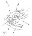
- a fifth wheel 1 is shown in three dimensions.
- the fifth wheel 1 is arranged on a towing vehicle, not shown here, and serves for the movable connection of the towing vehicle with a trailer also not shown here a semi-trailer combination.
- a so-called kingpin which is arranged on the front lower side of the trailer, in a coupling claw 2 of the fifth wheel 1.
- the fifth wheel 1 essentially comprises a coupling plate 4 and two bearing blocks 5, of which only one bearing block 5 is shown on the left side in the direction of travel x of the towing vehicle.
- the bearing block 5 has two areas with different functions: a storage area 6 and a fixing area 7.
- a storage area 6 there are bearing elements which serve for the pivotable mounting of the coupling plate 4 about a pivot axis y.
- the pivot axis y extends transversely to the direction of travel x of the towing vehicle.
- screws 8 can be seen, with which the bearing block 5 is attached to the frame 3 of the towing vehicle.
- the bearing block 5 is fastened in an advantageous manner by means of screws 8 on the vertical side surface 9 of the vehicle frame 3. Due to the lateral screw connection it is achieved that the assembly and disassembly can be carried out on existing vehicle frames also very simple.
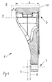
- the bearing block 5 is shown by itself cut perpendicular to the direction of travel x.
- a receiving area 10 which is provided on the underside of the clutch plate 4 for receiving the bearing block 5, indicated schematically.
- the horizontal side surface 9 of the vehicle frame 3 for attachment of the bearing block 5 is indicated.
- the bearing block 5 has a width b which is at least 2.5 times as large as the width of the bearing block 5 in the mounting area 7.
- the bearing block 5 is produced as a one-piece molded part.
- the shape is calculated so that the required rigidity is achieved at a minimum molding weight.
- the storage area 6 is mechanically processed after casting such that a clearance S remains free in the assembled state between the storage area 6 of the bearing block 5 and the receiving area 10 of the fifth-wheel coupling plate 4.
- This unilaterally released clearance S on the vehicle interior serves to compensate for movements of the clutch plate 4 in the direction of the pivot axis y.
- bearing block such a clearance S is also provided on the vehicle interior side.
- a cross member, which was previously mounted to accommodate these transverse forces between the bearing blocks 5, is no longer necessary.
- the assembly and disassembly of the cross member in the hard to reach area under the coupling plate 4 is eliminated.
- the bearing blocks 5 can be adapted to existing fifth wheels and existing vehicle frames.
- the present fifth wheel 1 with the newly dimensioned bearing blocks 5 allows, with constant load capacity, a weight and consequently a fuel saving for Sattelschlepperkombination.
Landscapes
- Engineering & Computer Science (AREA)
- Combustion & Propulsion (AREA)
- Transportation (AREA)
- Mechanical Engineering (AREA)
- Chemical & Material Sciences (AREA)
- Vehicle Cleaning, Maintenance, Repair, Refitting, And Outriggers (AREA)
- Body Structure For Vehicles (AREA)
- Braking Arrangements (AREA)
- Arrangement And Driving Of Transmission Devices (AREA)
- Pharmaceuticals Containing Other Organic And Inorganic Compounds (AREA)
- Seats For Vehicles (AREA)
- Control Of Motors That Do Not Use Commutators (AREA)
- Polysaccharides And Polysaccharide Derivatives (AREA)
- Handcart (AREA)
- Agricultural Machines (AREA)
Description
- Die Erfindung bezieht sich auf eine Sattelkupplung umfassend eine Kupplungsplatte und einen Lagerbock zur bewegbaren Befestigung der Kupplungsplatte an einem Rahmen eines Zugfahrzeuges, wobei der Lagerbock einen Lagerungsbereich und einen Befestigungsbereich aufweist, wobei der Lagerungsbereich zur schwenkbaren Lagerung der Kupplungsplatte und der Befestigungsbereich zur lösbaren Befestigung der Kupplungsplatte an dem Rahmen des Zugfahrzeuges ausgebildet sind, wobei in Fahrtrichtung und parallel zur Schwenkachse geschnitten, der Lagerungsbereich einen grösseren Querschnitt als der Befestigungsbereich aufweist, wobei der Lagerbock im Lagerungsbereich in Richtung der Schwenkachse eine Breite aufweist, die kleiner ist als die Breite eines Aufnahmebereiches, der zur Aufnahme des Lagerbocks an die Kupplungsplatte ausgebildet ist, derart, dass der Lagerungsbereich des Lagerbockes mit einem Spielraum in dem Aufnahmebereich der Kupplungsplatte angeordnet ist.
- Im Kraftfahrzeugverkehr werden vermehrt Sattelschlepper mit Sattelkupplungen eingesetzt. Ein Zugfahrzeug weist eine Kupplungsplatte auf, in die ein Zapfen, der sogenannte Königszapfen des Anhängers eingekuppelt wird. Der Anhänger liegt dabei relativ frei beweglich auf einer Sattelkupplungsplatte des Zugfahrzeuges auf. Die Sattelkupplungsplatte ist über zwei Lagerböcke mit dem Rahmen des Zugfahrzeuges verbunden. Die Lagerböcke enthalten Lagerelemente, die quer zur Fahrtrichtung des Zugfahrzeuges angeordnet sind und ein Schwenken der Kupplungsplatte um eine Schwenkachse quer zur Fahrtrichtung ermöglichen.
- Aus der WO 01/34454 A1 ist eine gattungsgemässe Sattelkupplung bekannt. Die Lagerböcke, die jeweils auf der linken und rechten Seite des Fahrzeugrahmens befestigt sind, sind mittels einer Querstrebe parallel zur Schwenkachse miteinander verbunden. Die Querstrebe kann auch als Vorsprung am jeweiligen Lagerbock auf der Innenseite des Fahrzeuges ausgebildet sein. Die Lagerböcke, die Vorsprünge und/oder die Querstreben sind über der waagrechten Fläche der Rahmenkonstruktion des Zugfahrzeuges angeordnet und leiten Kräfte in die waagrechte Fläche des Fahrzeugrahmens ein,
- Ausgehend von diesem Stand der Technik ist es Aufgabe der Erfindung, eine Sattelkupplung anzugeben, die aus möglichst wenigen Einzelteilen aufgebaut ist, die möglichst wenig Gewicht aufweist und mit bestehenden Sattelkupplungsplatten kompatibel ist.
- Diese Aufgabe wird gelöst durch eine Sattelkupplung umfassend eine Kupplungsplatte und einen Lagerbock zur bewegbaren Befestigung der Kupplungsplatte an einem Rahmen eines Zugfahrzeuges, wobei der Lagerbock einen Lagerungsbereich und einen Befestigungsbereich aufweist, wobei der Lagerungsbereich zur schwenkbaren Lagerung der Kupplungsplatte und der Befestigungsbereich zur lösbaren Befestigung der Kupplungsplatte an dem Rahmen des Zugfahrzeuges ausgebildet sind, wobei in Fahrtrichtung und parallel zur Schwenkachse geschnitten, der Lagerungsbereich einen grösseren Querschnitt als der Befestigungsbereich aufweist, wobei der Lagerbock im Lagerungsbereich in Richtung der Schwenkachse eine Breite aufweist, die kleiner ist als die Breite eines Aufnahmebereiches, der zur Aufnahme des Lagerbocks an die Kupplungsplatte ausgebildet ist, derart, dass der Lagerungsbereich des Lagerbockes mit einem Spielraum in dem Aufnahmebereich der Kupplungsplatte angeordnet ist, wobei der Spielraum zum Auffangen der Relativbewegungen zwischen der Kupplungsplatte und dem Lagerbock in der Richtung der Schwenkachse im Bereich der Fahrzeuginnenseite des Lagerbockes ausgebildet ist.
- Bevorzugte Weiterbildungen der Erfindung ergeben sich aus den abhängigen Ansprüchen.
- Es ist von Vorteil, dass die Sattelkupplung aus möglichst wenigen Einzelteilen aufgebaut werden kann. Dies wird dadurch erreicht, dass die Lagerböcke aus einem einstückigen Gussformteil ausgebildet sind.
- Ein Ausführungsbeispiel der Erfindung wird anhand der Figuren beschrieben. Es zeigen:
- Figur 1
- eine dreidimensionale Sicht auf eine erfindungsgcmässe Sattelkupplung.
- Figur 2
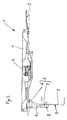
- eine Sicht auf die Sattelkupplung von Figur 1 in Fahrtrichtung und
- Figur 3
- einen Schnitt durch einen Lagerbock senkrecht zur Fahrtrichtung.
- In Figur 1 ist eine Sattelkupplung 1 dreidimensional dargestellt. Die Sattelkupplung 1 ist an einem hier nicht dargestellten Zugfahrzeug angeordnet und dient zur beweglichen Verbindung des Zugfahrzeuges mit einem hier ebenfalls nicht dargestellten Anhänger einer Sattelschlepperkombination. Wenn der Anhänger mit dem Zugfahrzeug gekuppelt ist, befindet sich ein sogenannter Königszapfen, der auf der vorderen unteren Seite des Anhängers angeordnet ist, in einer Kupplungsklaue 2 der Sattelkupplung 1. Vom Zugfahrzeug ist lediglich ein Teilbereich eines Rahmens 3 dargestellt. Die Sattelkupplung 1 umfasst im wesentlichen eine Kupplungsplatte 4 und zwei Lagerböcke 5, von denen hier nur einen Lagerbock 5 auf der linken Seite in Fahrtrichtung x des Zugfahrzeuges dargestellt ist.
- Der Lagerbock 5 weist zwei Bereiche mit unterschiedlichen Funktionen auf: einen Lagerungsbereich 6 und einen Befestigungsbereich 7. Im Lagerungsbereich 6 befinden sich Lagerelemente, die zur schwenkbaren Lagerung der Kupplungsplatte 4 um eine Schwenkachse y dienen. Die Schwenkachse y verläuft quer zur Fahrtrichtung x des Zugfahrzeuges. Im Befestigungsbereich 7 sind Schrauben 8 ersichtlich, mit denen der Lagerbock 5 am Rahmen 3 des Zugfahrzeuges befestigt ist. Der Lagerbock 5 wird in vorteilhafter Weise mittels Schrauben 8 an der senkrechten Seitenfläche 9 des Fahrzeugrahmens 3 befestigt. Durch die seitliche Verschraubung wird erreicht, dass die Montage und Demontage denkbar einfach auch an bestehenden Fahrzeugrahmen durchgeführt werden kann.
- In Figur 2 ist die Sattelkupplung 1 von Figur 1 nochmals, gesehen in der Fahrtrichtung x des Zugfahrzeuges dargestellt. Hier ist gut ersichtlich, wie der Befestigungsbereich 7 des Lagerbockes 5 mit Schrauben 8 an der senkrechten Seitenfläche des Fahrzeugrahmens 3 befestigt ist. Auf der waagrechten Fläche des Fahrzeugrahmens 3, die im zusammengebauten Zustand des Zugfahrzeuges eine denkbar schlecht zugängliche Fläche ist, sind keine Befestigungen oder Abstützungen erforderlich. In Figur 2 wurde zur besseren Übersichtlichkeit der zweite Lagerbock 5 auf der rechten Seite der Kupplungsplatte 4 weggelassen. Die Bezugszeichen in Figur 2 beziehen sich auf den gleichen Merkmalen, wie in Figur 1 beschrieben.
- In Figur 3 ist der Lagerbock 5 für sich alleine geschnitten senkrecht zur Fahrtrichtung x dargestellt. Mit gestrichelten Linien im Lagerungsbereich 6 ist ein Aufnahmebereich 10, der auf der Unterseite der Kupplungsplatte 4 zur Aufnahme des Lagerbockes 5 vorgesehen ist, schematisch angedeutet. Mit weiteren gestrichelten Linien im Befestigungsbereich 7 ist die waagrechte Seitenfläche 9 des Fahrzeugrahmens 3 zur Befestigung des Lagerbockes 5 angedeutet. Im Lagerungsbereich 6 weist der Lagerbock 5 eine Breite b auf, die mindestens 2.5 mal so gross ist als die Breite des Lagerbockes 5 im Befestigungsbereich 7. Der Lagerbock 5 wird als einstückiges Gussformteil hergestellt.
- Bei der Dimensionierung des Gussformteiles wird die Form so berechnet, dass die erforderliche Steifigkeit bei einem minimalen Formteilgewicht erreicht wird. Auf der Fahrzeuginnenseite wird der Lagerungsbereich 6 nach dem Giessen mechanisch derart bearbeitet, dass im zusammengebauten Zustand zwischen dem Lagerungsbereich 6 des Lagerbockes 5 und dem Aufnahmebereich 10 der Sattelkupplungsplatte 4 einen Spielraum S frei bleibt. Dieser einseitig frei gelassene Spielraum S auf der Fahrzeuginnenseite dient zum Ausgleichen von Bewegungen der Kupplungsplatte 4 in Richtung der Schwenkachse y. Bei dem gegenüberliegenden, hier nicht abgebildeten Lagerbock ist ebenfalls auf der Fahrzeuginnenseite ein solcher Spielraum S vorgesehen.
- Diese Spielräume S nehmen jeweils bei einer Verformung in Richtung der Schwenkachse y die Lagerungsbereiche 6 der Lagerböcke 5 auf. Hiermit wird erreicht, dass Querkräfte, die im Betriebszustand auf die Sattelkupplung 1 von der Fahrzeugaussenseite in Richtung auf die Fahrzeuginnenseite wirken, ausgeglichen werden.
- Eine Querstrebe, die bisher zur Aufnahme dieser Querkräfte zwischen den Lagerböcken 5 montiert wurde, ist nicht mehr erforderlich. Die Montage und Demontage der Querstrebe in dem schwer zugänglichen Bereich unter der Kupplungsplatte 4 entfällt. Die Lagerböcke 5 können an bestehenden Sattelkupplungen und bestehenden Fahrzeugrahmen angepasst werden. Die vorliegende Sattelkupplung 1 mit den neu dimensionierten Lagerböcken 5 ermöglicht, bei gleichbleibender Tragfähigkeit, eine Gewichts- und daraus folgend eine Treibstoffeinsparung für die Sattelschlepperkombination.
Claims (4)
- Sattelkupplung (1) umfassend eine Kupplungsplatte (4) und einen Lagerbock (5) zur bewegbaren Befestigung der Kupplungsplatte (4) an einem Rahmen (3) eines Zugfahrzeuges, wobei der Lagerbock (5) einen Lagerungsbereich (6) und einen Befestigungsbereich (7) aufweist, wobei der Lagerungsbereich (6) zur schwenkbaren Lagerung der Kupplungsplatte (4) und der Befestigungsbereich (7) zur lösbaren Befestigung der Kupplungsplatte (4) an dem Rahmen (3) des Zugfahrzeuges ausgebildet sind, wobei in Fahrtrichtung (x) und parallel zur Schwenkachse (y) geschnitten, der Lagerungsbereich (6) einen grösseren Querschnitt als der Befestigungsbereich (7) aufweist, wobei der Lagerbock (5) im Lagerungsbereich (6) in Richtung der Schwenkachse (y) eine Breite (b) aufweist, die kleiner ist als die Breite eines Aufnahmebereiches (10), der zur Aufnahme des Lagerbocks (5) an die Kupplungsplatte (4) ausgebildet ist, derart, dass der Lagerungsbereich (6) des Lagerbockes (5) mit einem Spielraum (S) in dem Aufnahmebereich (10) der Kupplungsplatte (4) angeordnet ist, dadurch gekennzeichnet, dass der Spielraum (S) zum Auffangen der Relativbewegungen zwischen der Kupplungsplatte (4) und dem Lagerbock (5) in der Richtung der Schwenkachse (y) im Bereich der Fahrzeuginnenseite des Lagerbockes (5) ausgebildet ist.
- Sattelkupplung nach dem Anspruch 1, dadurch gekennzeichnet, dass der Befestigungsbereich (7) des Lagerbockes (5) mittels Schrauben (8) lösbar befestigbar an einer senkrecht verlaufend angeordneten Seitenfläche (9) des Rahmens (3) des Zugfahrzeuges angeordnet ist.
- Sattelkupplung nach mindestens einem der Ansprüche 1 oder 2, dadurch gekennzeichnet, dass die Breite (b) des Lagerungsbereiches (6) in der Richtung der Schwenkachse (y) mindestens 2,5-mal so gross ist wie die Breite des Befestigungsbereiches (7) des Lagerbockes (5).
- Sattelkupplung nach mindestens einem der Ansprüche 1 bis 3, dadurch gekennzeichnet, dass der Lagerbock (5) aus einem einstückigen Gussformteil ausgebildet ist.
Applications Claiming Priority (3)
| Application Number | Priority Date | Filing Date | Title |
|---|---|---|---|
| DE10257807 | 2002-12-10 | ||
| DE10257807.9A DE10257807B4 (de) | 2002-12-10 | 2002-12-10 | Sattelkupplung |
| PCT/EP2003/012171 WO2004052713A2 (de) | 2002-12-10 | 2003-10-31 | Sattelkupplung |
Publications (3)
| Publication Number | Publication Date |
|---|---|
| EP1578658A2 EP1578658A2 (de) | 2005-09-28 |
| EP1578658B1 true EP1578658B1 (de) | 2007-01-03 |
| EP1578658B2 EP1578658B2 (de) | 2013-02-27 |
Family
ID=32336197
Family Applications (1)
| Application Number | Title | Priority Date | Filing Date |
|---|---|---|---|
| EP03812582A Expired - Lifetime EP1578658B2 (de) | 2002-12-10 | 2003-10-31 | Sattelkupplung |
Country Status (10)
| Country | Link |
|---|---|
| US (1) | US7487990B2 (de) |
| EP (1) | EP1578658B2 (de) |
| CN (1) | CN100391777C (de) |
| AT (1) | ATE350268T1 (de) |
| AU (1) | AU2003276229A1 (de) |
| DE (2) | DE10257807B4 (de) |
| DK (1) | DK1578658T3 (de) |
| ES (1) | ES2276163T5 (de) |
| PT (1) | PT1578658E (de) |
| WO (1) | WO2004052713A2 (de) |
Families Citing this family (5)
| Publication number | Priority date | Publication date | Assignee | Title |
|---|---|---|---|---|
| EP2161183B1 (de) | 2005-09-15 | 2013-07-17 | SAF-HOLLAND Verkehrstechnik GmbH | Sattelkupplung |
| USD670212S1 (en) * | 2010-07-26 | 2012-11-06 | Cequent Performance Products, Inc. | Fifth wheel hitch |
| USD670211S1 (en) * | 2010-07-26 | 2012-11-06 | Cequent Performance Products, Inc. | Fifth wheel hitch skid plate cover |
| EP3078579B1 (de) | 2013-05-22 | 2019-03-20 | SAF-Holland, Inc. | Ersatzrad-kupplungsanordnung mit direkt montierten halteklammern |
| USD837103S1 (en) * | 2016-09-19 | 2019-01-01 | Iveco S.P.A. | Towing attachment for vehicles |
Family Cites Families (16)
| Publication number | Priority date | Publication date | Assignee | Title |
|---|---|---|---|---|
| US2336939A (en) * | 1940-09-06 | 1943-12-14 | American Steel Foundries | Fifth wheel mounting |
| DE1031141B (de) * | 1956-04-09 | 1958-05-29 | American Steel Foundries | Sattelschlepperkupplung |
| CN86210718U (zh) * | 1986-12-20 | 1987-12-12 | 湖南省汽车车桥厂 | 一种球墨铸铁牵引座 |
| US4762334A (en) * | 1987-11-03 | 1988-08-09 | Amsted Industries Incorporated | Fifth wheel bracket mounting assembly |
| US5368324A (en) * | 1994-01-10 | 1994-11-29 | Amsted Industries Incorporated | Mounting system for fifth wheels |
| US5464241A (en) * | 1994-07-25 | 1995-11-07 | Holland Hitch Company | Plural height powered fifth wheel hitch |
| DE4426840A1 (de) * | 1994-07-28 | 1996-02-01 | Rockinger Spezial Fab Joh | Sattelzugfahrzeug |
| US5746438A (en) * | 1995-03-03 | 1998-05-05 | Jost--Werke AG | Fifth wheel |
| JP3465836B2 (ja) * | 1995-10-09 | 2003-11-10 | 株式会社 ソーシン | カプラにおける緩衝支持構造 |
| US5765849A (en) * | 1996-04-24 | 1998-06-16 | Fontaine Fifth Wheel Co. | Fifth wheel bracket |
| DE19727338C2 (de) * | 1997-06-27 | 2003-10-30 | Jost Werke Gmbh & Co Kg | Sattelkupplung |
| DE19813635A1 (de) * | 1998-03-27 | 1999-09-30 | Jost Werke Ag | Sattelkupplung |
| GB9821363D0 (en) * | 1998-10-02 | 1998-11-25 | Vbg Limited | Fifth wheel coupler |
| DE19952997C5 (de) * | 1999-11-04 | 2013-09-26 | Jost-Werke Gmbh | Befestigungsvorrichtung für eine Sattelkupplung an einem Fahrzeugrahmen |
| SE516661C2 (sv) * | 1999-11-12 | 2002-02-12 | Scania Cv Ab | Kopplingsanordning omfattande vändskiva |
| DE10213148C1 (de) * | 2002-03-23 | 2003-07-03 | Jost Werke Gmbh & Co Kg | Sattelkupplung |
-
2002
- 2002-12-10 DE DE10257807.9A patent/DE10257807B4/de not_active Expired - Lifetime
-
2003
- 2003-10-31 CN CNB200380105649XA patent/CN100391777C/zh not_active Expired - Fee Related
- 2003-10-31 AU AU2003276229A patent/AU2003276229A1/en not_active Abandoned
- 2003-10-31 US US10/538,541 patent/US7487990B2/en not_active Expired - Fee Related
- 2003-10-31 AT AT03812582T patent/ATE350268T1/de not_active IP Right Cessation
- 2003-10-31 WO PCT/EP2003/012171 patent/WO2004052713A2/de not_active Ceased
- 2003-10-31 DE DE50306229T patent/DE50306229D1/de not_active Expired - Lifetime
- 2003-10-31 ES ES03812582T patent/ES2276163T5/es not_active Expired - Lifetime
- 2003-10-31 EP EP03812582A patent/EP1578658B2/de not_active Expired - Lifetime
- 2003-10-31 PT PT03812582T patent/PT1578658E/pt unknown
- 2003-10-31 DK DK03812582T patent/DK1578658T3/da active
Also Published As
| Publication number | Publication date |
|---|---|
| US7487990B2 (en) | 2009-02-10 |
| DE10257807A1 (de) | 2004-06-24 |
| WO2004052713A3 (de) | 2004-08-05 |
| EP1578658A2 (de) | 2005-09-28 |
| AU2003276229A1 (en) | 2004-06-30 |
| ES2276163T3 (es) | 2007-06-16 |
| CN100391777C (zh) | 2008-06-04 |
| DE50306229D1 (de) | 2007-02-15 |
| CN1723148A (zh) | 2006-01-18 |
| ES2276163T5 (es) | 2013-05-30 |
| EP1578658B2 (de) | 2013-02-27 |
| PT1578658E (pt) | 2007-04-30 |
| DE10257807B4 (de) | 2014-03-27 |
| DK1578658T3 (da) | 2007-05-07 |
| WO2004052713A2 (de) | 2004-06-24 |
| US20060170190A1 (en) | 2006-08-03 |
| ATE350268T1 (de) | 2007-01-15 |
Similar Documents
| Publication | Publication Date | Title |
|---|---|---|
| DE69917167T2 (de) | Fahrzeugvorderwagenaufbau | |
| EP0861765B1 (de) | Fahrschemel | |
| EP1216856B2 (de) | Anhängevorrichtung für ein Arbeitsfahrzeug | |
| DE60012362T2 (de) | Befestigungsvorrichtung einer sattelkupplung | |
| DE102008028351B4 (de) | Fahrwerksbauteil | |
| EP1578658B1 (de) | Sattelkupplung | |
| DE4426840A1 (de) | Sattelzugfahrzeug | |
| DE19809281A1 (de) | Fahrgestell eines schweren Nutzfahrzeuges | |
| DE102013107914B4 (de) | Trageinrichtung und Fahrgestell | |
| EP2605951B1 (de) | Lageranordnung einer sattelkupplung | |
| DE3151280C2 (de) | Fahrgestellrahmen für Fahrzeuge, insbesondere Omnibusse | |
| DE102019206649A1 (de) | Aggregatvorrichtung für ein Kraftfahrzeug, Kraftfahrzeug mit einer Aggregatvorrichtung und Verfahren zum Verstellen einer Aggregatvorrichtung | |
| EP2457752B1 (de) | Kupplungsvorrichtung und Anhängevorrichtung für Zugfahrzeuge | |
| DE19809279A1 (de) | Fahrgestell eines schweren Nutzfahrzeuges | |
| DE102005022102B4 (de) | Schwanenhals mit integrierter Achse bzw. integrierten Achsen für Auflieger | |
| DE69514215T2 (de) | Spielfreie Zugstangenanordnung für einen Güterwagon | |
| DE202015002528U1 (de) | Zwischenwagen für einen Fahrzeugverbund | |
| DE69611022T2 (de) | Kupplungsvorrichtung zwischen einem Zugwagen und einem Anhänger mit Fahrspursteuerung des Anhängers | |
| EP0501150B1 (de) | Kraftfahrzeug mit einer Anhängevorrichtung | |
| DE102010053083A1 (de) | Sattelkupplung mit einstellbarer Höhe | |
| EP0940324A1 (de) | Fahrgestell eines schweren Nutzfahrzeuges | |
| DE3934121A1 (de) | Gekroepfte zuggabel fuer mehrachsige, drehschemelgelenkte anhaengerfahrzeuge | |
| EP0538893B1 (de) | Sattelzugfahrzeug | |
| EP0319765A2 (de) | Kupplungseinrichtung | |
| DE3523742A1 (de) | Lastzug |
Legal Events
| Date | Code | Title | Description |
|---|---|---|---|
| PUAI | Public reference made under article 153(3) epc to a published international application that has entered the european phase |
Free format text: ORIGINAL CODE: 0009012 |
|
| 17P | Request for examination filed |
Effective date: 20050420 |
|
| AK | Designated contracting states |
Kind code of ref document: A2 Designated state(s): AT BE BG CH CY CZ DE DK EE ES FI FR GB GR HU IE IT LI LU MC NL PT RO SE SI SK TR |
|
| AX | Request for extension of the european patent |
Extension state: AL LT LV MK |
|
| DAX | Request for extension of the european patent (deleted) | ||
| GRAP | Despatch of communication of intention to grant a patent |
Free format text: ORIGINAL CODE: EPIDOSNIGR1 |
|
| GRAS | Grant fee paid |
Free format text: ORIGINAL CODE: EPIDOSNIGR3 |
|
| GRAA | (expected) grant |
Free format text: ORIGINAL CODE: 0009210 |
|
| AK | Designated contracting states |
Kind code of ref document: B1 Designated state(s): AT BE BG CH CY CZ DE DK EE ES FI FR GB GR HU IE IT LI LU MC NL PT RO SE SI SK TR |
|
| PG25 | Lapsed in a contracting state [announced via postgrant information from national office to epo] |
Ref country code: FI Free format text: LAPSE BECAUSE OF FAILURE TO SUBMIT A TRANSLATION OF THE DESCRIPTION OR TO PAY THE FEE WITHIN THE PRESCRIBED TIME-LIMIT Effective date: 20070103 Ref country code: SI Free format text: LAPSE BECAUSE OF FAILURE TO SUBMIT A TRANSLATION OF THE DESCRIPTION OR TO PAY THE FEE WITHIN THE PRESCRIBED TIME-LIMIT Effective date: 20070103 |
|
| REG | Reference to a national code |
Ref country code: GB Ref legal event code: FG4D Free format text: NOT ENGLISH |
|
| GBT | Gb: translation of ep patent filed (gb section 77(6)(a)/1977) |
Effective date: 20070103 |
|
| REF | Corresponds to: |
Ref document number: 50306229 Country of ref document: DE Date of ref document: 20070215 Kind code of ref document: P |
|
| REG | Reference to a national code |
Ref country code: IE Ref legal event code: FG4D Free format text: LANGUAGE OF EP DOCUMENT: GERMAN |
|
| REG | Reference to a national code |
Ref country code: HU Ref legal event code: AG4A Ref document number: E001093 Country of ref document: HU |
|
| REG | Reference to a national code |
Ref country code: SE Ref legal event code: TRGR |
|
| REG | Reference to a national code |
Ref country code: GR Ref legal event code: EP Ref document number: 20070400844 Country of ref document: GR |
|
| REG | Reference to a national code |
Ref country code: PT Ref legal event code: SC4A Free format text: AVAILABILITY OF NATIONAL TRANSLATION Effective date: 20070328 |
|
| REG | Reference to a national code |
Ref country code: DK Ref legal event code: T3 |
|
| ET | Fr: translation filed | ||
| REG | Reference to a national code |
Ref country code: ES Ref legal event code: FG2A Ref document number: 2276163 Country of ref document: ES Kind code of ref document: T3 |
|
| PLBI | Opposition filed |
Free format text: ORIGINAL CODE: 0009260 |
|
| PLAX | Notice of opposition and request to file observation + time limit sent |
Free format text: ORIGINAL CODE: EPIDOSNOBS2 |
|
| 26 | Opposition filed |
Opponent name: JOST-WERKE GMBH Effective date: 20070929 |
|
| PG25 | Lapsed in a contracting state [announced via postgrant information from national office to epo] |
Ref country code: SK Free format text: LAPSE BECAUSE OF FAILURE TO SUBMIT A TRANSLATION OF THE DESCRIPTION OR TO PAY THE FEE WITHIN THE PRESCRIBED TIME-LIMIT Effective date: 20070103 |
|
| NLR1 | Nl: opposition has been filed with the epo |
Opponent name: JOST-WERKE GMBH |
|
| PG25 | Lapsed in a contracting state [announced via postgrant information from national office to epo] |
Ref country code: RO Free format text: LAPSE BECAUSE OF FAILURE TO SUBMIT A TRANSLATION OF THE DESCRIPTION OR TO PAY THE FEE WITHIN THE PRESCRIBED TIME-LIMIT Effective date: 20070103 |
|
| PLAF | Information modified related to communication of a notice of opposition and request to file observations + time limit |
Free format text: ORIGINAL CODE: EPIDOSCOBS2 |
|
| PLBB | Reply of patent proprietor to notice(s) of opposition received |
Free format text: ORIGINAL CODE: EPIDOSNOBS3 |
|
| PG25 | Lapsed in a contracting state [announced via postgrant information from national office to epo] |
Ref country code: MC Free format text: LAPSE BECAUSE OF NON-PAYMENT OF DUE FEES Effective date: 20071031 |
|
| PG25 | Lapsed in a contracting state [announced via postgrant information from national office to epo] |
Ref country code: EE Free format text: LAPSE BECAUSE OF FAILURE TO SUBMIT A TRANSLATION OF THE DESCRIPTION OR TO PAY THE FEE WITHIN THE PRESCRIBED TIME-LIMIT Effective date: 20070103 |
|
| PGFP | Annual fee paid to national office [announced via postgrant information from national office to epo] |
Ref country code: CH Payment date: 20081015 Year of fee payment: 6 Ref country code: CZ Payment date: 20081027 Year of fee payment: 6 Ref country code: DK Payment date: 20081015 Year of fee payment: 6 Ref country code: IE Payment date: 20081023 Year of fee payment: 6 |
|
| PGFP | Annual fee paid to national office [announced via postgrant information from national office to epo] |
Ref country code: BG Payment date: 20081016 Year of fee payment: 6 |
|
| APBM | Appeal reference recorded |
Free format text: ORIGINAL CODE: EPIDOSNREFNO |
|
| APBP | Date of receipt of notice of appeal recorded |
Free format text: ORIGINAL CODE: EPIDOSNNOA2O |
|
| APAH | Appeal reference modified |
Free format text: ORIGINAL CODE: EPIDOSCREFNO |
|
| PGFP | Annual fee paid to national office [announced via postgrant information from national office to epo] |
Ref country code: GR Payment date: 20081017 Year of fee payment: 6 |
|
| PG25 | Lapsed in a contracting state [announced via postgrant information from national office to epo] |
Ref country code: CY Free format text: LAPSE BECAUSE OF FAILURE TO SUBMIT A TRANSLATION OF THE DESCRIPTION OR TO PAY THE FEE WITHIN THE PRESCRIBED TIME-LIMIT Effective date: 20070103 |
|
| APBQ | Date of receipt of statement of grounds of appeal recorded |
Free format text: ORIGINAL CODE: EPIDOSNNOA3O |
|
| PG25 | Lapsed in a contracting state [announced via postgrant information from national office to epo] |
Ref country code: LU Free format text: LAPSE BECAUSE OF NON-PAYMENT OF DUE FEES Effective date: 20071031 |
|
| PGFP | Annual fee paid to national office [announced via postgrant information from national office to epo] |
Ref country code: AT Payment date: 20091022 Year of fee payment: 7 |
|
| PGFP | Annual fee paid to national office [announced via postgrant information from national office to epo] |
Ref country code: PT Payment date: 20091023 Year of fee payment: 7 Ref country code: HU Payment date: 20080930 Year of fee payment: 6 |
|
| PGFP | Annual fee paid to national office [announced via postgrant information from national office to epo] |
Ref country code: BE Payment date: 20091029 Year of fee payment: 7 |
|
| REG | Reference to a national code |
Ref country code: CH Ref legal event code: PL |
|
| REG | Reference to a national code |
Ref country code: DK Ref legal event code: EBP |
|
| PG25 | Lapsed in a contracting state [announced via postgrant information from national office to epo] |
Ref country code: HU Free format text: LAPSE BECAUSE OF NON-PAYMENT OF DUE FEES Effective date: 20091101 |
|
| PG25 | Lapsed in a contracting state [announced via postgrant information from national office to epo] |
Ref country code: CZ Free format text: LAPSE BECAUSE OF NON-PAYMENT OF DUE FEES Effective date: 20091031 |
|
| PG25 | Lapsed in a contracting state [announced via postgrant information from national office to epo] |
Ref country code: GR Free format text: LAPSE BECAUSE OF NON-PAYMENT OF DUE FEES Effective date: 20100504 Ref country code: CH Free format text: LAPSE BECAUSE OF NON-PAYMENT OF DUE FEES Effective date: 20091031 Ref country code: IE Free format text: LAPSE BECAUSE OF NON-PAYMENT OF DUE FEES Effective date: 20091031 Ref country code: LI Free format text: LAPSE BECAUSE OF NON-PAYMENT OF DUE FEES Effective date: 20091031 |
|
| PG25 | Lapsed in a contracting state [announced via postgrant information from national office to epo] |
Ref country code: DK Free format text: LAPSE BECAUSE OF NON-PAYMENT OF DUE FEES Effective date: 20091031 |
|
| PG25 | Lapsed in a contracting state [announced via postgrant information from national office to epo] |
Ref country code: BG Free format text: LAPSE BECAUSE OF FAILURE TO SUBMIT A TRANSLATION OF THE DESCRIPTION OR TO PAY THE FEE WITHIN THE PRESCRIBED TIME-LIMIT Effective date: 20091031 |
|
| BERE | Be: lapsed |
Owner name: GEORG FISCHER VERKEHRSTECHNIK G.M.B.H. Effective date: 20101031 |
|
| REG | Reference to a national code |
Ref country code: PT Ref legal event code: MM4A Free format text: LAPSE DUE TO NON-PAYMENT OF FEES Effective date: 20110502 |
|
| PG25 | Lapsed in a contracting state [announced via postgrant information from national office to epo] |
Ref country code: PT Free format text: LAPSE BECAUSE OF NON-PAYMENT OF DUE FEES Effective date: 20110502 |
|
| PG25 | Lapsed in a contracting state [announced via postgrant information from national office to epo] |
Ref country code: BE Free format text: LAPSE BECAUSE OF NON-PAYMENT OF DUE FEES Effective date: 20101031 Ref country code: AT Free format text: LAPSE BECAUSE OF NON-PAYMENT OF DUE FEES Effective date: 20101031 |
|
| REG | Reference to a national code |
Ref country code: DE Ref legal event code: R082 Ref document number: 50306229 Country of ref document: DE Representative=s name: MUELLER SCHUPFNER & PARTNER PATENT- UND RECHTS, DE Effective date: 20110729 Ref country code: DE Ref legal event code: R081 Ref document number: 50306229 Country of ref document: DE Owner name: SAF-HOLLAND VERKEHRSTECHNIK GMBH, DE Free format text: FORMER OWNER: SAF-HOLLAND, INC., HOLLAND, US Effective date: 20110729 Ref country code: DE Ref legal event code: R081 Ref document number: 50306229 Country of ref document: DE Owner name: SAF-HOLLAND VERKEHRSTECHNIK GMBH, DE Free format text: FORMER OWNER: SAF-HOLLAND, INC., HOLLAND, MICH., US Effective date: 20110729 Ref country code: DE Ref legal event code: R081 Ref document number: 50306229 Country of ref document: DE Owner name: SAF-HOLLAND GMBH, DE Free format text: FORMER OWNER: SAF-HOLLAND, INC., HOLLAND, MICH., US Effective date: 20110729 |
|
| PLAB | Opposition data, opponent's data or that of the opponent's representative modified |
Free format text: ORIGINAL CODE: 0009299OPPO |
|
| R26 | Opposition filed (corrected) |
Opponent name: JOST-WERKE GMBH Effective date: 20070929 |
|
| APBU | Appeal procedure closed |
Free format text: ORIGINAL CODE: EPIDOSNNOA9O |
|
| RAP2 | Party data changed (patent owner data changed or rights of a patent transferred) |
Owner name: SAF-HOLLAND VERKEHRSTECHNIK GMBH |
|
| PUAH | Patent maintained in amended form |
Free format text: ORIGINAL CODE: 0009272 |
|
| STAA | Information on the status of an ep patent application or granted ep patent |
Free format text: STATUS: PATENT MAINTAINED AS AMENDED |
|
| 27A | Patent maintained in amended form |
Effective date: 20130227 |
|
| AK | Designated contracting states |
Kind code of ref document: B2 Designated state(s): AT BE BG CH CY CZ DE DK EE ES FI FR GB GR HU IE IT LI LU MC NL PT RO SE SI SK TR |
|
| REG | Reference to a national code |
Ref country code: DE Ref legal event code: R102 Ref document number: 50306229 Country of ref document: DE Effective date: 20130227 |
|
| REG | Reference to a national code |
Ref country code: SE Ref legal event code: RPEO |
|
| REG | Reference to a national code |
Ref country code: ES Ref legal event code: DC2A Ref document number: 2276163 Country of ref document: ES Kind code of ref document: T5 Effective date: 20130530 |
|
| REG | Reference to a national code |
Ref country code: NL Ref legal event code: T3 Ref country code: NL Ref legal event code: TD Effective date: 20130607 |
|
| PG25 | Lapsed in a contracting state [announced via postgrant information from national office to epo] |
Ref country code: GR Free format text: LAPSE BECAUSE OF FAILURE TO SUBMIT A TRANSLATION OF THE DESCRIPTION OR TO PAY THE FEE WITHIN THE PRESCRIBED TIME-LIMIT Effective date: 20130528 |
|
| REG | Reference to a national code |
Ref country code: ES Ref legal event code: GC2A Effective date: 20150708 |
|
| REG | Reference to a national code |
Ref country code: FR Ref legal event code: PLFP Year of fee payment: 13 |
|
| REG | Reference to a national code |
Ref country code: FR Ref legal event code: PLFP Year of fee payment: 14 |
|
| REG | Reference to a national code |
Ref country code: FR Ref legal event code: PLFP Year of fee payment: 15 |
|
| REG | Reference to a national code |
Ref country code: DE Ref legal event code: R082 Ref document number: 50306229 Country of ref document: DE Representative=s name: MUELLER SCHUPFNER & PARTNER PATENT- UND RECHTS, DE Ref country code: DE Ref legal event code: R081 Ref document number: 50306229 Country of ref document: DE Owner name: SAF-HOLLAND GMBH, DE Free format text: FORMER OWNER: SAF-HOLLAND VERKEHRSTECHNIK GMBH, 78224 SINGEN, DE |
|
| REG | Reference to a national code |
Ref country code: FR Ref legal event code: PLFP Year of fee payment: 16 |
|
| PGFP | Annual fee paid to national office [announced via postgrant information from national office to epo] |
Ref country code: NL Payment date: 20191022 Year of fee payment: 17 |
|
| PGFP | Annual fee paid to national office [announced via postgrant information from national office to epo] |
Ref country code: IT Payment date: 20191021 Year of fee payment: 17 Ref country code: FR Payment date: 20191022 Year of fee payment: 17 Ref country code: ES Payment date: 20191120 Year of fee payment: 17 |
|
| PGFP | Annual fee paid to national office [announced via postgrant information from national office to epo] |
Ref country code: GB Payment date: 20191023 Year of fee payment: 17 |
|
| REG | Reference to a national code |
Ref country code: NL Ref legal event code: MM Effective date: 20201101 |
|
| GBPC | Gb: european patent ceased through non-payment of renewal fee |
Effective date: 20201031 |
|
| PG25 | Lapsed in a contracting state [announced via postgrant information from national office to epo] |
Ref country code: NL Free format text: LAPSE BECAUSE OF NON-PAYMENT OF DUE FEES Effective date: 20201101 Ref country code: FR Free format text: LAPSE BECAUSE OF NON-PAYMENT OF DUE FEES Effective date: 20201031 |
|
| PG25 | Lapsed in a contracting state [announced via postgrant information from national office to epo] |
Ref country code: GB Free format text: LAPSE BECAUSE OF NON-PAYMENT OF DUE FEES Effective date: 20201031 |
|
| PG25 | Lapsed in a contracting state [announced via postgrant information from national office to epo] |
Ref country code: IT Free format text: LAPSE BECAUSE OF NON-PAYMENT OF DUE FEES Effective date: 20201031 |
|
| REG | Reference to a national code |
Ref country code: ES Ref legal event code: FD2A Effective date: 20220128 |
|
| PG25 | Lapsed in a contracting state [announced via postgrant information from national office to epo] |
Ref country code: ES Free format text: LAPSE BECAUSE OF NON-PAYMENT OF DUE FEES Effective date: 20201101 |
|
| PGFP | Annual fee paid to national office [announced via postgrant information from national office to epo] |
Ref country code: TR Payment date: 20221021 Year of fee payment: 20 Ref country code: SE Payment date: 20221020 Year of fee payment: 20 Ref country code: DE Payment date: 20220804 Year of fee payment: 20 |
|
| P01 | Opt-out of the competence of the unified patent court (upc) registered |
Effective date: 20230504 |
|
| REG | Reference to a national code |
Ref country code: DE Ref legal event code: R071 Ref document number: 50306229 Country of ref document: DE |
|
| REG | Reference to a national code |
Ref country code: SE Ref legal event code: EUG |