EP1578009A2 - Dauermagnetische Vorrichtung zur Übertragung einer Drehbewegung, hermetische Rühreinheit, und Elektroschmelzaggregat - Google Patents
Dauermagnetische Vorrichtung zur Übertragung einer Drehbewegung, hermetische Rühreinheit, und Elektroschmelzaggregat Download PDFInfo
- Publication number
- EP1578009A2 EP1578009A2 EP05005768A EP05005768A EP1578009A2 EP 1578009 A2 EP1578009 A2 EP 1578009A2 EP 05005768 A EP05005768 A EP 05005768A EP 05005768 A EP05005768 A EP 05005768A EP 1578009 A2 EP1578009 A2 EP 1578009A2
- Authority
- EP
- European Patent Office
- Prior art keywords
- magnetic pole
- magnets
- magnetic
- pole portion
- rotation body
- Prior art date
- Legal status (The legal status is an assumption and is not a legal conclusion. Google has not performed a legal analysis and makes no representation as to the accuracy of the status listed.)
- Withdrawn
Links
Images


Classifications
-
- H—ELECTRICITY
- H02—GENERATION; CONVERSION OR DISTRIBUTION OF ELECTRIC POWER
- H02K—DYNAMO-ELECTRIC MACHINES
- H02K49/00—Dynamo-electric clutches; Dynamo-electric brakes
- H02K49/10—Dynamo-electric clutches; Dynamo-electric brakes of the permanent-magnet type
- H02K49/104—Magnetic couplings consisting of only two coaxial rotary elements, i.e. the driving element and the driven element
- H02K49/108—Magnetic couplings consisting of only two coaxial rotary elements, i.e. the driving element and the driven element with an axial air gap
-
- B—PERFORMING OPERATIONS; TRANSPORTING
- B01—PHYSICAL OR CHEMICAL PROCESSES OR APPARATUS IN GENERAL
- B01F—MIXING, e.g. DISSOLVING, EMULSIFYING OR DISPERSING
- B01F33/00—Other mixers; Mixing plants; Combinations of mixers
- B01F33/45—Magnetic mixers; Mixers with magnetically driven stirrers
- B01F33/453—Magnetic mixers; Mixers with magnetically driven stirrers using supported or suspended stirring elements
- B01F33/4532—Magnetic mixers; Mixers with magnetically driven stirrers using supported or suspended stirring elements using a bearing, tube, opening or gap for internally supporting the stirring element
-
- B—PERFORMING OPERATIONS; TRANSPORTING
- B01—PHYSICAL OR CHEMICAL PROCESSES OR APPARATUS IN GENERAL
- B01F—MIXING, e.g. DISSOLVING, EMULSIFYING OR DISPERSING
- B01F33/00—Other mixers; Mixing plants; Combinations of mixers
- B01F33/45—Magnetic mixers; Mixers with magnetically driven stirrers
- B01F33/453—Magnetic mixers; Mixers with magnetically driven stirrers using supported or suspended stirring elements
- B01F33/4535—Magnetic mixers; Mixers with magnetically driven stirrers using supported or suspended stirring elements using a stud for supporting the stirring element
-
- C—CHEMISTRY; METALLURGY
- C30—CRYSTAL GROWTH
- C30B—SINGLE-CRYSTAL GROWTH; UNIDIRECTIONAL SOLIDIFICATION OF EUTECTIC MATERIAL OR UNIDIRECTIONAL DEMIXING OF EUTECTOID MATERIAL; REFINING BY ZONE-MELTING OF MATERIAL; PRODUCTION OF A HOMOGENEOUS POLYCRYSTALLINE MATERIAL WITH DEFINED STRUCTURE; SINGLE CRYSTALS OR HOMOGENEOUS POLYCRYSTALLINE MATERIAL WITH DEFINED STRUCTURE; AFTER-TREATMENT OF SINGLE CRYSTALS OR A HOMOGENEOUS POLYCRYSTALLINE MATERIAL WITH DEFINED STRUCTURE; APPARATUS THEREFOR
- C30B15/00—Single-crystal growth by pulling from a melt, e.g. Czochralski method
- C30B15/30—Mechanisms for rotating or moving either the melt or the crystal
-
- F—MECHANICAL ENGINEERING; LIGHTING; HEATING; WEAPONS; BLASTING
- F27—FURNACES; KILNS; OVENS; RETORTS
- F27B—FURNACES, KILNS, OVENS OR RETORTS IN GENERAL; OPEN SINTERING OR LIKE APPARATUS
- F27B14/00—Crucible or pot furnaces
- F27B14/04—Crucible or pot furnaces adapted for treating the charge in vacuum or special atmosphere
-
- F—MECHANICAL ENGINEERING; LIGHTING; HEATING; WEAPONS; BLASTING
- F27—FURNACES; KILNS; OVENS; RETORTS
- F27B—FURNACES, KILNS, OVENS OR RETORTS IN GENERAL; OPEN SINTERING OR LIKE APPARATUS
- F27B14/00—Crucible or pot furnaces
- F27B14/06—Crucible or pot furnaces heated electrically, e.g. induction crucible furnaces with or without any other source of heat
- F27B14/061—Induction furnaces
-
- F—MECHANICAL ENGINEERING; LIGHTING; HEATING; WEAPONS; BLASTING
- F27—FURNACES; KILNS; OVENS; RETORTS
- F27B—FURNACES, KILNS, OVENS OR RETORTS IN GENERAL; OPEN SINTERING OR LIKE APPARATUS
- F27B14/00—Crucible or pot furnaces
- F27B14/08—Details specially adapted for crucible or pot furnaces
- F27B14/10—Crucibles
-
- F—MECHANICAL ENGINEERING; LIGHTING; HEATING; WEAPONS; BLASTING
- F27—FURNACES; KILNS; OVENS; RETORTS
- F27D—DETAILS OR ACCESSORIES OF FURNACES, KILNS, OVENS OR RETORTS, IN SO FAR AS THEY ARE OF KINDS OCCURRING IN MORE THAN ONE KIND OF FURNACE
- F27D27/00—Stirring devices for molten material
-
- H—ELECTRICITY
- H02—GENERATION; CONVERSION OR DISTRIBUTION OF ELECTRIC POWER
- H02K—DYNAMO-ELECTRIC MACHINES
- H02K49/00—Dynamo-electric clutches; Dynamo-electric brakes
- H02K49/10—Dynamo-electric clutches; Dynamo-electric brakes of the permanent-magnet type
- H02K49/104—Magnetic couplings consisting of only two coaxial rotary elements, i.e. the driving element and the driven element
- H02K49/106—Magnetic couplings consisting of only two coaxial rotary elements, i.e. the driving element and the driven element with a radial air gap
-
- Y—GENERAL TAGGING OF NEW TECHNOLOGICAL DEVELOPMENTS; GENERAL TAGGING OF CROSS-SECTIONAL TECHNOLOGIES SPANNING OVER SEVERAL SECTIONS OF THE IPC; TECHNICAL SUBJECTS COVERED BY FORMER USPC CROSS-REFERENCE ART COLLECTIONS [XRACs] AND DIGESTS
- Y10—TECHNICAL SUBJECTS COVERED BY FORMER USPC
- Y10S—TECHNICAL SUBJECTS COVERED BY FORMER USPC CROSS-REFERENCE ART COLLECTIONS [XRACs] AND DIGESTS
- Y10S366/00—Agitating
- Y10S366/605—Paint mixer
Definitions
- the present invention relates to a magnetic rotation transmitting device transmitting the rotation by an electric coupling, a hermetic stirring unit driving a stirring blade inside a hermetic container by the magnetic rotation transmitting device, and an electric furnace driving a pulling shaft of a single crystal or a crucible rotating shaft by using the magnetic rotation transmitting device.
- a magnetic rotation transmitting device transmitting a large torque (the moment of power around a rotating shaft. A product obtained by multiplying a distance from the rotating shaft to a point of action of the force by a value of the force.) is required.
- the size of respective magnets in the drive side and the driven side is required to be large, however, it is difficult to manufacture a large-sized permanent magnet having an uniform magnetic performance, and there exists a limit to allow the magnet to be large.
- the present invention is made to solve the aforementioned problems, and an object of the present invention is to provide a magnet rotation transmitting device capable of obtaining large transmitting torque without using large-sized permanent magnets.
- a magnetic rotation transmitting device relating to claim 1 of the present invention is an axial-type magnetic rotation transmitting device, which includes a driving rotation body having one or plural magnetic line(s) in which plural first magnets (10A) are disposed in a circumferential direction on a first disk (11A) at almost equal intervals, a drive source rotationally driving a drive shaft of the driving rotation body, and a driven rotation body having one or plural magnet line(s) in which second magnets (20A) of the same number as the first magnets (10A) are disposed in the circumferential direction on a second disk (21A) at almost equal intervals, symmetrically disposed to, and magnetically coupled with the driving rotation body with a magnetic coupling gap and, which utilizes a magnetic operation and which allows the driven rotation body to rotate by rotationally driving the drive shaft by means of the drive source, characterized in that the first magnet (10A) has a N-magnetic pole portion and a S-magnetic pole portion, and an extended surface of
- a magnetic rotation transmitting device relating to claim 2 is a radial-type magnetic rotation transmitting device, which includes a driving rotation body having one or plural magnetic line(s) in which plural first magnets (10B) are disposed in a circumferential direction on an inner wall of a cylinder (11B) at almost equal intervals, a drive source rotationally driving a drive shaft of the driving rotation body, and a driven rotation body having one or plural magnet line(s) in which second magnets (20B) of the same number as the first magnets (10B) are disposed in the circumferential direction on an outer wall of a column (21B) housed in the cylinder (11B) at almost equal intervals, symmetrically disposed to, and magnetically coupled with the driving rotation body with a magnetic coupling gap, which utilizes a magnetic operation and which allows the driven rotation body to rotate by rotationally driving the drive shaft by means of the drive source, characterized in that the first magnet (10B) has a N-magnetic pole portion and a S-magnetic pole portion, and
- a hermetic stirring unit relating to claim 3 of the present invention is a hermetic stirring unit including a hermetic container (31A), a stirring blade (32A), a driven shaft (52A) and a magnetic rotation transmitting device, in which the magnetic rotation transmitting device is an axial-type magnetic rotation transmitting device which includes a driving rotation body having one or plural magnetic line(s) in which plural first magnets (10A) are disposed in a circumferential direction on a first disk (11A) at almost equal intervals, a drive source (41A) rotationally driving a drive shaft (42A) of the driving rotation body, and a driven rotation body having one or plural magnet line(s) in which second magnets (20A) of the same number as the first magnets (10A) are disposed in the circumferential direction on a second disk (21A) at almost equal intervals, symmetrically disposed to, and magnetically coupled with the driving rotation body with a magnetic coupling gap; which utilizes a magnetic operation and which allows the driven shaft (52A) to
- a hermetic stirring unit relating to claim 4 of the present invention is a hermetic stirring unit including a hermetic container (31B), a stirring blade (32B), a driven shaft (52B) and a magnetic rotation transmitting device, in which the magnetic rotation transmitting device is a radial-type magnetic rotation transmitting device which includes a driving rotation body having one or plural magnetic line(s) in which plural first magnets (10B) are disposed in a circumferential direction on an inner wall of a cylinder (11B) at almost equal intervals, a drive source (41B) rotationally driving a drive shaft (42B) of the driving rotation body, and a driven rotation body having one or plural magnet line(s) in which second magnets (20B) of the same number as the first magnets (10B) are disposed in the circumferential direction on an outer wall of a column (21B) housed in a cylinder (11B) at almost equal intervals, symmetrically disposed to, and magnetically coupled with the driving rotation body with a magnetic coupling
- a hermetic stirring unit relating to claim 5 of the present invention is a hermetic stirring unit including a hermetic container (31C) having a fixing shaft (33A) thereinside, a stirring blade and a magnetic rotation transmitting device, in which the magnetic rotation transmitting device is an axial-type magnetic rotation transmitting device which includes a driving rotation body having one or plural magnetic line(s) in which plural first magnets (10A) are disposed in a circumferential direction on a first disk (11A) at almost equal intervals, a drive source (41C) rotationally driving a drive shaft (42C) of the driving rotation body, and a driven rotation body having one or plural magnet line(s) in which second magnets (20C) of the same number as the first magnets (10A) are disposed in the circumferential direction on a second disk (21C) at almost equal intervals, symmetrically disposed to, and magnetically coupled with the driving rotation body with a magnetic coupling gap, which utilizes a magnetic operation and which allows the driven rotation body to rotate by
- a hermetic stirring unit relating to claim 6 of the present invention is a hermetic stirring unit including a hermetic container (31D) having a fixing shaft (33B) thereinside, a stirring blade, and a magnetic rotation transmitting device, in which the magnetic rotation transmitting device is a radial-type magnetic rotation transmitting device which includes a driving rotation body having one or plural magnetic line(s) in which plural first magnets (10C) are disposed in a circumferential direction on an outer wall of a column (11C) at almost equal intervals, a drive source (41D) rotationally driving a drive shaft (42D) of the driving rotation body, and a driven rotation body having one or plural magnet line(s) in which second magnets (20D) of the same number as the first magnets (10C) are disposed in the circumferential direction on an inner wall of a cylinder (21D) housing the column at almost equal intervals, symmetrically disposed to, and magnetically coupled with the driving rotation body with a magnetic coupling gap, which utilizes
- An electric furnace relating to claim 7 is an electric furnace including a pressure resistant vessel, a crucible provided in the pressure-resistant vessel, a crucible supporting shaft supporting the crucible, a heating means heating materials in the crucible, a pulling shaft of a single crystal for pulling up a crystal from the crucible, and a radial-type magnetic rotation transmitting device rotating the pulling shaft and/or the crucible supporting shaft, in which the radial-type magnetic rotation transmitting device includes a drive rotation body having one or plural magnet line(s) in which plural first magnets (10B), (10B) are disposed on an outer periphery to a lower hermetic barrel unit (67) and an upper hermetic barrel unit (68) at almost equal intervals, and a driven rotation body having one or plural magnet line(s) in which second magnets (20B), (20B) of the same number as the respective first magnets (10B), (10B) are disposed in a circumferential direction on outer walls of second rotating columns (21B), (21B) housed in
- An electric furnace relating to claim 8 is an electric furnace including a pressure resistant vessel, a crucible provided in the pressure-resistant vessel, a crucible supporting shaft supporting the crucible, a heating means heating materials in the crucible, and an axial-type magnetic rotation transmitting device rotating the crucible, in which the axial-type magnetic rotation transmitting device includes a driving rotation body having one or plural magnet line(s) in which plural first magnets (10A) are disposed in a circumferential direction on a first disk (11A) at almost equal intervals, a drive source (41A) rotationally driving a drive shaft (42A) of the driving rotation body, and a driven rotation body having one or plural magnet line(s) in which second magnets (20A) of the same number as the first magnets (10A) are disposed in the circumferential direction on a second disk (21A) at almost equal intervals, symmetrically disposed to, and magnetically coupled with the driving rotation body with a magnetic coupling gap, which utilizes a magnetic operation and which allows the
- the hermetic stirring unit and the electric furnace relating to the present invention are constituted so that the plural first magnets are disposed in the circumferential direction on the disk, the cylinder, or the column in the drive side driven by the drive source at almost equal intervals, that the second magnets of the same number as the first magnets are disposed in the circumference direction on the disk, the column, or the cylinder installed facing the disk and the like in the drive side at almost equal intervals, that the magnetic coupling gap is provided between the first magnets and the second magnets, that adjacent and facing surfaces of the first magnets adjacent to each other on the disk and the like in the drive side are disposed so that the magnetic pole faces having the same polarity make pairs, and that adjacent and facing surfaces of the second magnets adjacent to each other on the disk and the like in the driven side are disposed so that the magnetic pole faces having the same polarity make pairs, as a result, the magnetic force in the space where the same magnetic pole faces of the first magnets in the drive side make pairs (
- the first magnets and the second magnet are plural and same in number. Therefore, even if the magnetic force of one first magnet or one second magnet is same as the normal magnetic force, the magnetic force reinforcing effect obtained by allowing the same magnetic pole faces to be pairs as described above is added to the magnetic force of the product obtained by multiplying the magnetic force of one first magnet by the number of the first magnets in the whole first magnets in the drive side, and the magnetic force reinforcing effect by allowing the same magnetic pole faces to be pairs as described above is added to the magnetic force of the product obtained by multiplying the magnetic force of one second magnet by the number of the second magnets in the whole second magnets in the driven side, resultingly, the torque to be transmitted to the driven side can be increased as the whole magnetic rotation transmitting device and as the whole hermetic stirring unit.
- Embodiments which will be described hereinafter have structure in which plural first magnets as being permanent magnets are disposed in a circumference direction at almost equal intervals on a disk, a cylinder or a column in a drive side driven by a drive source, in which second magnets as being permanent magnets of the same number as the first magnets in the circumference direction at almost equal intervals on the disk, the column or the cylinder in a driven side disposed facing to the disk and so on in the drive side, in which a magnetic coupling gap is arranged between the first magnets and the second magnets, in which adjacent and facing surfaces of the first magnets adjacent to each other on the disk and so on in the drive side are disposed so that magnetic pole faces having same polarity make pairs, and in which adjacent and facing surfaces of the second magnets adjacent to each other in the disk and so on in the driven side are disposed so that the magnetic pole faces having same polarity make pairs.
- FIG. 1A and FIG. 1B are views showing a structure of a magnetic rotation transmitting device as being the first embodiment of the present invention.
- FIG. 1B is a sectional view seen from a side surface of the magnetic rotation transmitting device of the first embodiment of the present invention.
- FIG. 1A is a bottom view of a first disk 11A (later described) looked up from below in Fig. 1B.
- the magnetic rotation transmitting device of the first embodiment of the present invention is constituted by including driving rotation body having a first disk 11A and a first magnet 10A, and a driven rotation body having a second disk 21A and a second magnet 20A.
- the first disk 11A is a member made of materials which are not magnetized or which do not tend to be magnetized (nonmagnetic materials), for example, nonmagnetic metal materials (such as an austenitic stainless steel, an aluminum alloy and the like), or an FRP (fiber reinforced plastic) and the like, and formed to be a disk shape or a circular-plate shape.
- nonmagnetic materials such as an austenitic stainless steel, an aluminum alloy and the like
- FRP fiber reinforced plastic
- the first magnet 10A is a permanent magnet, which is formed to be a columnar solid shape having a sector cross-sectional shape.
- the permanent magnet an alnico magnet, a ferrite magnet, rare-earth magnets and a bond magnet can be used.
- the rare-earth magnets a samarium-cobalt magnet, a neodymium-iron-boron magnet, a samarium-iron-nitrogen magnet, a platinum-iron magnet, a platinum-cobalt magnet, a manganese-aluminum magnet, an iron-chromium-cobalt magnet and the like can be used.
- the eight first magnets 10A are disposed on the first disk 11A in a circumferential direction at almost equal intervals.
- the eight first magnets 10A disposed side-by-side circumferentially correspond to one magnet line in claims.
- a planar shape of an individual first magnet 10A is approximately sectorial, and a center line of the sector practically overlaps with a nearly radial straight line running through the center of a circle of the first disk 11A.
- the aforementioned first magnet 10A has a N-magnetic pole portion denoted as a symbol 'N' in FIG. 1A and a S-magnetic pole portion denoted as a symbol 'S' in FIG. 1A.
- a boundary surface between the N-magnetic pole portion and the S-magnetic pole portion is allowed to approximately correspond to the center line of the sector formed by the first magnet 10A, and an extended surface of the boundary surface between the N-magnetic pole portion and the S-magnetic pole portion is disposed so as to practically overlap with, or practically contact a rotation center line of a driving rotation body (hereinafter, referred to as a driving center line).
- Adjacent and facing surfaces (side surfaces) of the two first magnets 10A, 10A adjacent to each other on the first disk 11A are disposed so that magnetic pole faces having same polarity make a pair (one set).
- the adjacent and facing surfaces of the two first magnets 10A, 10A adjacent to each other on the first disk 11A are disposed so that a N-pole faces a N-pole, and a S pole faces a S-pole.
- the pair of the N-pole and the N-pole is denoted as (N, N) and the pair of the S-pole and the S-pole is denoted as (S, S).
- a mortise for a drive shaft 12A is provided (refer to FIG. 1B).
- a straight line connecting the center of the first disk 11A to the center of the mortise for the drive shaft 12A approximately corresponds to the driving center line of the driving rotation body .
- a drive shaft (not shown) of a drive source such as an electric motor (not shown) can be fitted to the mortise for the drive shaft 12A, and the driving rotation body is allowed to be rotationally driven by the drive source.
- the rotation center line of the drive shaft approximately corresponds to the driving center line.
- the second disk 21A is a member made of the materials which are not magnetized or which do not tend to be magnetized (nonmagnetic materials), for example, the nonmagnetic metal materials (such as the austenitic stainless steel, the aluminum alloy), or the FRP (fiber reinforced plastic) and the like, and formed to be the disk shape or the circular-plate shape.
- nonmagnetic materials such as the austenitic stainless steel, the aluminum alloy
- FRP fiber reinforced plastic
- the second magnet 20A is a permanent magnet, which is formed to be a columnar solid shape having a sector cross-sectional shape.
- the permanent magnet the alnico magnet, the ferrite magnet, the rare-earth magnets and the bond magnet can be used.
- the rare-earth magnets the samarium-cobalt magnet, the neodymium-iron-boron magnet, the samarium-iron-nitrogen magnet, the platinum-iron magnet, the platinum-cobalt magnet, the manganese-aluminum magnet, the iron-chromium-cobalt magnet and the like can be used.
- the eight second magnets 20A of the same number as the eight first magnets 10A are disposed on the second disk 21A in a circumferential direction at almost equal intervals.
- the eight second magnets 20A disposed side-by-side circumferentially correspond to one magnet line in claims.
- the planar shape of an individual second magnet 20A is approximately sectorial, and the center line of the sector practically overlaps with the nearly radial straight line running through the center of a circle of the second disk 21A.
- An disposition state of the second magnets 20A (intervals between adjacent second magnets, differences of the central angle between adjacent second magnets or the like) is set to be similar to the disposition state of the first magnets 10A (intervals between adjacent first magnets, differences of the central angle between adjacent first magnets or the like).
- the second magnet 20A though a planar disposition state thereof is not shown, has the N-magnetic pole portion and the S-magnetic pole portion in the same way as the case of the first magnet 10A, disposed such that the boundary surface between the N-magnetic pole portion and the S-magnetic pole portion is allowed to approximately correspond to the center line of the sector formed by the second magnet 20A, and that an extended surface of the boundary surface between the N-magnetic pole portion and the S-magnetic pole portion practically overlaps with, or practically contacts the rotation center line of a driven rotation body (hereinafter, referred to as a driven center line).
- a driven center line a driven rotation body
- adjacent and facing surfaces (side surfaces) of the two second magnets 20A, 20A adjacent to each other on the second disk 21A are disposed so that magnetic pole faces having the same polarity make a pair (one set).
- the adjacent and facing surfaces of the two second magnets 20A, 20A adjacent to each other on the second disk 21A are disposed so that a N-pole faces a N-pole, and a S-pole faces a S-pole, namely, such as (N, N) and (S, S).
- a mortise for a drive shaft 22A is provided (refer to FIG. 1B).
- a straight line connecting the center of the second disk 21A to the center of the mortise for the drive shaft 22A approximately corresponds to the driven center line of the driven rotation body .
- a predetermined gap (hereinafter referred to as “magnetic coupling gap”) is set between a lower surface of the first magnet 10A and an upper surface of the second magnet 20A.
- a plate-shaped partition (partition plate) made of the nonmagnetic materials and the like is disposed between the lower surface of the first magnet 10A and the upper surface of the second magnet 20A as shown in FIG. 1B.
- a locking member (not shown) which does not move in an axial direction is attached to a bearing member of the drive shaft (not shown) installed to the driving rotation body
- the locking member (not shown) which does not move in the axial direction is attached to the bearing member of the driven shaft (not shown) installed to the driven rotation body.
- FIG. 2A to FIG. 2C are views of explaining the operation and principle of the magnetic rotation transmitting device as the first embodiment of the present invention.
- FIG. 2B shows a sectional view (the sectional view seen along A-A direction in FIG. 2A and FIG. 2C) seen from a side surface of the magnetic rotation transmitting device as one modification example of the first embodiment of the present invention
- FIG. 2A shows a bottom view looked up along the B-B direction in FIG. 2B
- FIG. 2C shows a top view looked down along the C-C direction in FIG. 2B, respectively.
- FIG. 3 is a graph explaining a characteristic of the magnetic rotation transmitting device as a first embodiment of the present invention.
- the magnetic rotation transmitting device as one modification example of the first embodiment of the present invention shown in FIG. 2A to FIG. 2C has the similar structure as the magnetic rotation transmitting device of the first embodiment shown in FIG. 1A and FIG. 1B, except that a first magnet 10A1 and a second magnet 20A1 have a nearly rectangular parallelepiped shape and that the first magnets 10A1 and the second magnets 20A1 are respectively six in number.
- a drive shaft (not shown) of a drive source such as an electric motor (not shown) can be fitted to a mortise for the drive shaft 12A1.
- the drive shaft (not shown) of the drive source such as the electric motor (not shown) is allowed to be fitted to the mortise for the drive shaft 12A1.
- the drive source such as the electric motor (not shown) is allowed to be actuated to rotationally drive a driving rotation body.
- a N-magnetic pole of a first magnet and a S-magnetic pole of a certain second magnet 20A1 are attracted to each other and a S-magnetic pole of the first magnet 10A1 and a N-magnetic pole of the second magnet 20A1 are attracted to each other.
- Such relation is called as a "magnetic coupling” and an attracting operation by the magnetic force is called as a "magnetic operation”.
- all the N-magnetic poles or the S-magnetic poles of the first magnets 10A1 can make the magnetic coupling relation attracted to each other between the N-magnetic poles or the S-magnetic poles of the second magnets 20A1.
- the second magnets 20A1 are attracted, then, the driven rotation body starts rotating, and finally, a rotational speed of the driven rotation body becomes equal to a rotational speed of the driving rotation body .
- the number of the first magnets 10A1 (six) is same as the number of the second magnets 20A1 (six).
- the magnetic force of one first magnet 10A1 or one second magnet 20A1 has approximately the same value as the ordinary magnetic force
- the magnetic force of the whole first magnets 10A1 in the drive side becomes the magnetic force of a product obtained by multiplying the magnetic force of one first magnet 10A1 by the number of the first magnets 10A1 (six).
- the magnetic force of the whole second magnets 20A1 in the driven side becomes the magnet force of the product obtained by multiplying the magnet force of one second magnet 20A1 by the number of the second magnets 20A1 (six).
- the adjacent and facing surfaces of the first magnets 10A1 adjacent to each other on the first disk 11A1 on the drive side are disposed so that the magnetic pole faces having same polarity make pairs
- the adjacent and facing surfaces of the second magnets 20A1 adjacent to each other on the second disk 21A1 on the driven side are disposed so that the magnetic pole faces having same polarity make pairs.
- the magnetic force in a space where the same magnetic pole faces of the first magnets 10A1 of the drive side are allowed to be pairs becomes stronger than the magnetic force in a normal space where magnetic pole faces different from each other are allowed to be pairs (hereinafter, referred to as a "different-polarity magnetic field space").
- the magnetic force in the space where the same magnetic pole faces of the first second magnets 20A1 in the driven side are allowed to be pairs becomes stronger than the magnetic force in the normal space where the magnetic pole faces different from each other are allowed to be pairs (hereinafter, referred to as a "different-polarity magnetic field space").
- a different-polarity magnetic field space such effect is referred to as “magnetic force reinforcing effect in the same-polarity magnetic field space”.
- the drive source such as the electric motor
- the same-polarity magnetic field space (N, N) in the first magnets 10A1 and the same-polarity magnetic field space (S, S) in the second magnets 20A1 having the driven rotation body are attracted to each other, and the adjacent same-polarity magnetic field space (S, S) in the driving rotation body and the adjacent same-polarity magnetic field space (N, N) in the driving rotation body are attracted to each other.
- all the same-polarity magnetic field space (S, S) or (N, N) in the driving rotation body can make a magnetic coupling relation attracted to each other between the corresponding same-polarity magnetic field space (S, S) or (N, N) of the driven rotation body.
- the same-polarity magnetic field space of the second magnets 20A1 is attracted, the driven rotation body starts rotating, and finally the driven rotation body rotates with the same speed as the driving rotation body .
- a rotation torque (transmitting torque) in the magnetic rotation transmitting device of the first embodiment can be represented by a following formula (1) when a value of torque is denoted as 'T' (unit: N ⁇ m, newton ⁇ meter), the thrust to a circumferential direction in the central position of magnet is denoted as 'f' (unit: N, Newton), a distance from the driving center line to the central position of the first magnet or a distance from the driven center line to the central position of the first magnet is denoted as 'r' (unit: m, meter), the number of the magnets is denoted as 'n' (unit: piece, dimensionless number) and coefficient showing a degree of increase and decrease of the magnetic force is denoted as 'k'.
- T f ⁇ r ⁇ n ⁇ k
- a result of an experiment is a graph of FIG. 3, which is performed with respect to the magnetic rotation transmitting device as the one modification example of the first embodiment of the present invention shown in FIG. 2A to FIG. 2C.
- a horizontal axis represents an angle of the driving rotation body rotated and shifted with respect to the driven rotation body (displacement angle, unit: degree).
- a right vertical axis represents a torque value (unit: N.m) at that time.
- a graph G1 is, as the example of FIGs.
- a graph G3 opposite to the example of FIGs.
- a different-polarity magnetic field type As a condition of the experiment, for the same-polarity magnetic field type magnets and the different-polarity magnetic field type magnets, the same magnets are used.
- the case of G1 of the same-polarity magnetic field type magnetic rotation transmitting device can transmit almost twice as much torque as the case of the G2 of the different-polarity magnetic field type magnetic rotation transmitting device, from the drive side to the driven side. Therefore, according to the experiment, the value of the coefficient 'k' in the formula (1) is approximately 2.0.
- a measurement of the thrust 'f' in the experiment of FIG. 3 is performed as follows.
- a piece of the first magnets 10A1 is picked up from the driving rotation body and a piece of the second magnets 20A1 is picked up from the driven rotation body.
- the first magnet 10A1 is fixed on an experiment table and the like, a spacer (gap keeping member) made of nonmagnetic materials for keeping the magnetic coupling gap is put thereon, and the second magnet 20A1 is further placed thereon.
- the S-magnetic pole of the second magnet 20A1 is just above the N-magnetic pole of the first magnet 10A1 through the spacer, and they stopped in a state being attracted to each other.
- the first magnets 10A described above are fixed to the first disk 11A by means of an adhesive or a mechanical joining such as a bolt.
- the first disk 11A is made of aluminum and the like, concave portions (not shown) in which the first magnets 10A are housed with no space therebetween are formed in the first disk 11A in advance. After the first magnets 10A are put into the concave portions, an upper surface of the first disk 11A in a periphery of the concave portion is struck by a tool such as a chisel toward a direction of the first magnet.
- the upper surface of the first disk 11A in the periphery of the first magnets 10A is plastic-deformed and covers the upper portion of first magnets 10A in such a state of "claws", as a result, the first magnets 10A are fixed to the first disk 11A by a "caulking".
- the process of fixing the second magnets 20A to the second disk 21A is similar to the above.
- the concave portions (not shown) in which the magnets are housed with no space therebetween are formed in the disk in advance, and after the magnets are put into the concave portions, a plate-shaped disk cover plate (not shown) made of nonmagnetic materials having approximately the same cross-sectional shape as the disk covers all the magnets and the disk cover plate is fixed to the disk by means of fixing members such as bolts or screws made of nonmagnetic material.
- the electric motor not shown corresponds to the drive source in claims.
- the magnetic rotation transmitting device having the structure of the above-described first embodiment is referred to as an" axial-type magnetic rotation transmitting device".
- a structure replacing the drive side portion with the driven side portion is also referred to as the "axial-type magnetic rotation transmitting device”.
- FIG. 4A and FIG. 4B are views showing a structure of the magnetic rotation transmitting device as the second embodiment of the present invention.
- the magnetic rotation transmitting device as the second embodiment of the present invention is constituted by including a driving rotation body having a cylinder 11B and first magnets 10B, and a driven rotation body having a column 21B and second magnets 20B.
- the cylinder 11B is the member made of nonmagnetic materials similar to the case of the first embodiment, which is formed to be the cylindrical shape.
- the first magnet 10B is a permanent magnet made of materials similar to the first embodiment, which is formed to be a columnar solid shape having a sector cross-sectional shape.
- the eight first magnets 10B are disposed in an inner wall of the cylinder 11B in a circumferential direction at almost equal intervals.
- the eight first magnet 10B disposed side-by-side circumferentially correspond to one magnet line in claims.
- a planar shape of an individual first magnet 10B is approximately sectorial, and a center line of the sector practically overlaps with a nearly radial straight line running through the center of a circle of the cylinder 11B.
- the aforementioned first magnet 10B has a N-magnetic pole portion denoted as a symbol 'N' in FIG. 4A and a S-magnetic pole portion denoted as a symbol 'S' in FIG. 4A.
- a boundary surface between the N-magnetic pole portion and the S-magnetic pole portion is allowed to approximately correspond to the center line of the sector formed by the first magnet 10B, and an extended surface of the boundary surface between the N-magnetic pole portion and the S-magnetic pole portion is disposed so as to practically overlap with, or practically contact a rotation center line of the driving rotation body (hereinafter, referred to as a "driving center line").
- Adjacent and facing surfaces (side surfaces) of the two first magnets 10B, 10B adjacent to each other on the cylinder 11B are disposed so that magnetic pole faces having same polarity make a pair (one set).
- the adjacent and facing surfaces of the two first magnets 10B, 10B adjacent to each other on the cylinder 11B are disposed so that a N-pole faces a N-pole, and a S-pole faces a S-pole.
- the pair of the N-pole and the N-pole is denoted as (N, N) and the pair of the S-pole and the S-pole is denoted as (S, S).
- a mortise for a drive shaft 12B is provided (refer to FIG. 4B).
- a straight line connecting the center of the cylinder 11B to the center of the mortise for the drive shaft 12B approximately corresponds to the driving center line of the driving rotation body .
- a drive shaft (not shown) of a drive source such as an electric motor (not shown) can be fitted to the mortise for the drive shaft 12B, and the driving rotation body is allowed to be rotationally driven by the drive source.
- the rotation center line approximately corresponds to the driving center line.
- the column 21B is the member made of nonmagnetic materials similar to the case of the first embodiment, which is formed to be the columnar shape.
- the second magnet 20B is a permanent magnet made of materials similar to the first embodiment, which is formed to be a columnar solid shape having a sector cross-sectional shape.
- the eight second magnets 20B as the same number as the first embodiment are disposed in an outer wall of the column 21B in a circumferential direction at almost equal intervals.
- the eight second magnet 20B disposed side-by-side circumferentially correspond to one magnet line in claims.
- a planar shape of an individual second magnet 20B is approximately sectorial, and a center line of the sector practically corresponds to a nearly radial straight line running through the center of a circle of the column 21B.
- An disposition state of the second magnets 20B (intervals between adjacent second magnets, differences of the central angle between adjacent second magnets or the like) is set to be similar to, or analogous to the disposition state of the first magnets 10B (intervals between adjacent first magnets, differences of the central angle between adjacent first magnets or the like).
- the second magnet 20B though a planar disposition state thereof is not shown, has the N-magnetic pole portion and the S-magnetic pole portion in the same way as the case of the first magnet 10B, disposed such that an extended surface of the boundary surface between the N-magnetic pole portion and the S-magnetic pole portion practically overlaps with, or practically contacts a rotation center line of the driving rotation body (hereinafter, referred to as a driven center line).
- a driven center line a rotation center line of the driving rotation body
- adjacent and facing surfaces (side surfaces) of the two second magnets 20B, 20B adjacent to each other on the column 21B are disposed so that magnetic pole faces having same polarity make a pair (one set).
- the adjacent and facing surfaces of the two second magnets 20B, 20B adjacent to each other on the column 21B are disposed so that a N-pole faces a N-pole, and a S-pole faces a S-pole, namely, such as (N, N) and (S, S).
- a mortise for a drive shaft 22B is provided (refer to FIG. 4B).
- a straight line connecting the center of the column 21B to the center of the mortise for the drive shaft 22B approximately corresponds to the driven center line of the driven rotation body.
- a predetermined gap (hereinafter referred to as “magnetic coupling gap”) is set between an outer surface of the first magnet 10B and an outer surface of the second magnet 20B.
- magnetic coupling gap As an attachment process or a fixing process of respective magnets to the cylinder or the column in the magnetic rotation transmitting device of the second embodiment, similar processes to the case of the aforementioned first embodiment can be employed. Concerning a securing process for the magnetic coupling gap, a similar process to the case of the first embodiment can also be employed.
- a magnetic force in a space where the same magnetic pole faces of the first magnets 10B in the drive side are allowed to be pairs becomes stronger than the magnetic force of the normal magnetic pole
- magnetic force in a space where the same magnetic pole faces of the second magnets 20B in the driven side are allowed to be the pair also becomes stronger than the magnetic force of the normal magnetic pole
- the first magnets 10B and the second magnets 20B are plural and same in number.
- the not-shown electric motor corresponds to the drive source in claims.
- the magnetic rotation transmitting device having the structure such as the aforementioned second embodiment is referred to as a "radial-type magnetic rotation transmitting device".
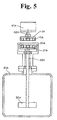
- FIG. 5 is a view showing a structure of a hermetic stirring unit as being the third embodiment of the present invention.
- the a hermetic stirring unit of the third embodiment of the present invention is constituted by including an axial-type magnetic rotation transmitting device, an electric motor 41A, a hermetic container 31A, a stirring blade 32A, and a driven shaft 52A.
- the hermetic container 31A is made of materials which are not magnetized or which do not tend to be magnetized (nonmagnetic materials), for example, nonmagnetic metal materials (such as an austenitic stainless steel, an aluminum alloy), a an FRP (fiber reinforced plastic) and the like.
- nonmagnetic materials such as an austenitic stainless steel, an aluminum alloy
- FRP fiber reinforced plastic
- the hermetic container 31A is hollow and has no opening as a whole, and a stirring tank portion thereof is a member formed to be various hollow solid shape such as hollow barrel bodies (for example, a hollow cylindrical body, hollow elliptic barrel body, a hollow square barrel body, a hollow polygonal barrel body or the like), a hollow spherical body, a hollow rotation elliptic body and the like.
- hollow barrel bodies for example, a hollow cylindrical body, hollow elliptic barrel body, a hollow square barrel body, a hollow polygonal barrel body or the like
- a hollow spherical body for example, a hollow cylindrical body, hollow elliptic barrel body, a hollow square barrel body, a hollow polygonal barrel body or the like
- a hollow spherical body for example, a hollow spherical body, a hollow rotation elliptic body and the like.
- a drive shaft 42A of the electric motor 41A is fitted to the mortise for the drive shaft 12A of the magnetic rotation transmitting device of the first embodiment shown in FIG. 1B to allow the shaft to be rotationally driven.
- a driven shaft 52A is fitted to the mortise for the driven shaft 22A of the magnetic rotation transmitting device of the first embodiment shown in FIG. 1B.
- a radial stirring blade 32A is attached to an lower end of the driven shaft 52A in the drawing. Note that, among the above components, the stirring blade 32A, the driven shaft 52A, the second disk 21A and the second magnets 20A of the magnetic rotation transmitting device, are housed inside the hermetic container 31A in a hermetic state.
- the hermetic container 31A Inside the hermetic container 31A, a substance which can not be stirred except in the hermetic state, the substance which is stirred under a condition of high-temperature or high-pressure environment, or under the a vacuum condition (hereinafter, referred to as a "substance to be stirred") and so on are sealed.
- the hermetic container 31A is composed of at least two portions (these portions have at least one opening respectively), and hermetically sealed by a bolt or sealant and the like. After the stirring of the substance to be stirred is finished, the hermetic container 31A is disassembled into two portions in another hermetic box and the like (not shown), and the stirred substance of the inside can be taken out from the aforementioned opening.
- the stirring blade 32A inside the hermetic container 31A is rotated, as a result, the substance to be stirred in the hermetic container 31A can be stirred.
- the electric motor 41A corresponds to the drive source in claims.
- FIG. 6 is a view showing a structure of a hermetic stirring unit as being the fourth embodiment of the present invention.
- the hermetic stirring unit of the fourth embodiment of the present invention is constituted by including a radial-type magnetic rotation transmitting device, an electric motor 41B, a hermetic container 31B, a stirring blade 32B and a driven shaft 52B.
- the radial-type magnetic rotation transmitting device is the device having the same structure and operation as the magnetic rotation transmitting device of the second embodiment shown in FIGs. 4, the explanation thereof is omitted. Additionally, since materials and shapes of the hermetic container 31B are similar to the hermetic container 31A, the explanation thereof is omitted.
- a drive shaft 42B of the electric motor 41B is fitted to a mortise for the drive shaft 12B of the magnetic rotation transmitting device of the second embodiment shown in FIG. 4B to allow the shaft to be rotationally driven.
- a driven shaft 42B is fitted to the mortise for the driven shaft 22B of the magnetic rotation transmitting device of the second embodiment shown in FIG. 4B.
- a radial stirring blade 32B is attached to an lower end of the driven shaft 52B in the drawing. Note that, among the above components, the stirring blade 32B, the driven shaft 52B, the column 21B and the second magnets 20B of the magnetic rotation transmitting device, are housed inside the hermetic container 31B in a hermetic state.
- the hermetic container 31B Inside the hermetic container 31B, a substance to be stirred similar to the case of the hermetic container 31A are sealed.
- the hermetic container 31B is composed of at least two portions (portions having at least one opening respectively), and hermetically sealed by a bolt or sealant and the like. After the stirring of the substance to be stirred is finished, the hermetic container 31B is disassembled into two portions in another hermetic box and the like, and the stirred substance of the inside can be taken out from the aforementioned opening.
- the stirring blade 32B inside the hermetic container 31B is rotated, as a result, the substance to be stirred in the hermetic container 31B can be stirred.
- the electric motor 41B corresponds to the drive source in claims.
- FIG. 7 is a view showing a structure of a hermetic stirring unit as being the fifth embodiment of the present invention.
- the hermetic stirring unit of the fifth embodiment of the present invention is constituted by including an axial-type magnetic rotation transmitting device, an electric motor 41C, a hermetic container 31C, a fixing shaft 33A, and bearing members 34A. Since materials and shapes of the hermetic container 31C are similar to the above-mentioned hermetic container 31A, the explanation thereof is omitted.
- the axial-type magnetic rotation transmitting device is constituted by including a driving rotation body having a first disk 11A and first magnets 10, and a driven rotation body having a second disk 21C and second magnets 20C, that is, the device having approximately the same structure and operation as the magnetic rotation transmitting device of the first embodiment shown in FIGs. 1.
- a driven-shaft through hole as being a through hole of a circular section formed so as to include a driven center line of the driven rotation body is provided, and that the fixing shaft 33A is inserted through the driven-shaft through hole and the driven rotation body is attached so as to be rotatable through the bearing members 34A.
- the fixing shaft 33A is a columnar part provided protrudingly from a bottom surface of the inside of the hermetic container 31A.
- the bearing members 34A is a member facilitating rotation by allowing rotation friction of the shaft to be decreased, which includes a ball bearing and is disposed around the fixing shaft 33A.
- a drive shaft 42C of the electric motor 41C is fitted to a mortise for the drive shaft 12A of the magnetic rotation transmitting device of the fisrt embodiment shown in FIG. 1B to allow the shaft to be rotationally driven.
- a stirring blade not shown is attached to the driven rotation body.
- the second disk 21C, the second magnets 20C, the bearing members 34A and the fixing shaft 33A of the magnetic rotation transmitting device are housed inside the hermetic container 31C in hermetic state.
- the hermetic container 31C Inside the hermetic container 31C, a substance to be stirred similar to the case of the hermetic container 31A are sealed.
- the hermetic container 31C is composed of at least two portions (portions having at least one opening respectively), and hermetically sealed by a bolt or sealant and the like. After the stirring of the substance to be stirred is finished, the hermetic container 31C is disassembled into two portions in another hermetic box and the like, and the stirred substance of the inside can be taken out from the aforementioned opening.
- the stirring blade inside the hermetic container 31C (for example, an not-shown additional stirring blade attached to the driven rotation body, or the second magnets 20C themselves) is rotated, as a result, the substance to be stirred in the hermetic container 31C can be stirred.
- the electric motor 41C corresponds to the drive source in claims.
- FIG. 8 is a view showing a structure of a hermetic stirring unit of the sixth embodiment of the present invention.
- the hermetic stirring unit of the sixth embodiment of the present invention is constituted by including an radial-type magnetic rotation transmitting device, an electric motor 41D, a hermetic container 31D, a fixing shaft 33B, and bearing members 34B. Since materials and shapes of the hermetic container 31D are similar to the above-mentioned hermetic container 31A, the explanation thereof is omitted.
- the radial-type magnetic rotation transmitting device is the device having different structure and operation from the magnetic rotation transmitting device of the second embodiment shown in Figs. 4. Different points of the radial-type magnetic rotation transmitting device shown in FIG. 8 from the magnetic rotation transmitting device of the second embodiment in FIGs.
- a driving rotation body is a inside column 11C (first magnets 10C are provided along a circumference of an outer surface thereof), that a driven rotation body is an outer cylinder 21D (second magnets 20D are provided along the circumference of an inner surface thereof), that a driven-shaft through hole as being a through hole of a circular section formed so as to include the driven center line of the driven rotation body is provided, and that the fixing shaft 33B is inserted into the driven-shaft through hole and the driven rotation body is attached so as to be rotatable through the bearing members 34A.
- the fixing shaft 33B is a columnar part provided protrudingly from a bottom surface of the inside of the hermetic container 31D.
- the bearing members 34B is a member facilitating rotation by allowing rotation friction of the shaft to be decreased, which includes a ball bearing and is disposed around the fixing shaft 33B.
- a drive shaft 42D of the electric motor 41D is fitted to a mortise for the drive shaft (not shown) provided at a lower part of the column 11C to allow the shaft to be rotationally driven.
- a stirring blade not shown is attached to the driven rotation body.
- the cylinder 21D, the second magnets 20D, the bearing members 34B and the fixing shaft 33B of the magnetic rotation transmitting device are housed inside the hermetic container 31D in hermetic state.
- the hermetic container 31D Inside the hermetic container 31D, a substance to be stirred similar to the case of the hermetic container 31A are sealed.
- the hermetic container 31D is composed of at least two portions (portions having at least one opening respectively), and hermetically sealed by a bolt or sealant and the like. After the stirring of the substance to be stirred is finished, the hermetic container 31D is disassembled into two portions in another hermetic box and the like, and the stirred substance of the inside can be taken out from the aforementioned opening.
- the stirring blade inside the hermetic container 31D (for example, an not-shown additional stirring blade attached to the driven rotation body, or an outer side of the cylinder 21D) is rotated, as a result, the substance to be stirred in the hermetic container 31D can be stirred.
- the electric motor 41D corresponds to the drive source in claims.
- the magnetic transmitting device in the hermetic stirring unit shown in FIG. 7 and the magnetic transmitting device in the hermetic stirring unit shown in FIG. 8 can be used by themselves.
- the magnetic transmitting device in the hermetic stirring unit shown in FIG. 8 is not installed to the fixing shaft 33B but the driven shaft 52A or 52B, and a stirring blade 32A or 32B as shown in FIG. 5 or FIG. 6 are installed to the magnetic transmitting device in the hermetic stirring unit shown in FIG. 8 to compose the hermetic stirring unit.
- the stirring blade (for example, 32A) can be installed to a sidewall inside the hermetic container, besides being provided at the bottom inside the hermetic container (for example, 31A).
- the stirring blade can also installed to a ceiling surface inside the hermetic container.
- two or more stirring blades and magnetic rotation transmitting devices for the blades can be provided.
- FIG. 9 shows an electric furnace 50 for pulling a single crystal such as a III-V group compound, as the seventh embodiment of the present invention.
- a so-called a Czochralski method in which a molten composition of GaAs, GaP, or InP and the like is formed in a crucible installed inside a pressure-resistant vessel by combining gallium (Ga) and arsenic (As), gallium (Ga) and phosphorus (P), or indium (In) and phosphorus (P), and a seed crystal attached to a tip of a pulling shaft is dipped into the molten composition, then, a single crystal is pulled up with the crucible and the seed crystal rotated to allow the single crystal such as GaAS, GaP or InP to grow in a circumferential direction or an axial direction to obtain an ingot.
- a Czochralski method LOC method
- the compound when the compound is combined or when the single crystal is pulled up, the compound is apt to combine with other elements especially in the pressure-resistant vessel, therefore, it is performed that the inside of the pressure-resistant vessel is allowed to be a high-pressure inert gas atmosphere by vacuumizing the inside of the pressure-resistant vessel to be vacuumized and introducing the inert gas such as nitrogen, argon or the like thereinto.
- the electric furnace for manufacturing the aforementioned III-V group, or II-IV group compounds requires a high hermeticity, therefore, a magnetic rotation transmitting device not reducing the hermeticity of the pressure-resistant vessel is required for a rotational drive transmitting device which rotationally driving the aforementioned crucible or the pulling shaft of the single crystal.
- an article denoted by an indicating numeral 51 is a pressure-resistant vessel made of, for example, stainless steel which is heat resistant, and in the axial direction of the central portion thereinside, a crucible 52 made of, for example, graphite is placed and fixed on a crucible placing table 53.
- Lower heating elements 54a made of, for example, carbon, are provided around the crucible 52.
- a supporting shaft 55 is attached to the crucible placing table 53 and extends into a lower hermetic barrel unit 67 of a magnetic rotation transmitting device 56 installed hermetically to a bottom lid 51a, piercing through the bottom lid 51a of the pressure-resistant vessel 51.
- a molten composition 57 of, for example, GaAs is contained, which is covered with a liquid sealant 58 such as B203 (boron oxide) on the top thereof, and a single crystal 59 grown from a seed crystal 60 is pulled up from the molten composition 57, rotating in one direction.
- a liquid sealant 58 such as B203 (boron oxide) on the top thereof
- a single crystal 59 grown from a seed crystal 60 is pulled up from the molten composition 57, rotating in one direction.
- upper heating elements 54b are provided therearound.
- the seed crystal 60 is fixed to a tip of a pulling shaft 61 of the single crystal, and the pulling shaft 61 extends into an upper hermetic barrel unit 68 of a magnetic rotation transmitting device 62 installed hermetically to a top lid 51b, piercing through the top lid 51b of the pressure-resistant vessel 51.
- lower bearing devices 65a, 65b, and 66c, and upper bearing devices 66a, 66b, and 66c are provided. Note that the number of the bearing devices does not limited.
- the aforementioned magnetic rotation transmitting device 56 rotating the crucible 52 is the radial-type one of the second embodiment shown in FIGs. 4, and the second rotation column 21D and the second magnets 20B provided at the crucible supporting shaft 55 are housed in the lower hermetic barrel unit 67 hermetically installed to the lower guide barrel unit 63.
- first magnets 10B of the aforementioned second embodiment are attached facing the second magnets 20B, the second magnets 20B are attached inside a cylinder 75, and the cylinder 75 is connected to a rotating shaft 77 of a drive motor 76 for rotating the crucible supporting shaft 55.
- the drive motor 76 is screwed to threaded rods 79, 79 hanging from the bottom lid 51a of the pressure-resistant vessel 51 at attachment portions thereof 78a, 78a.
- the threaded rods 79, 79 are rotated by a drive motor 86 through a drive force transmitting means 85 composed of, for example, pulleys 80, 80 over which a timing belt 81 is suspended, gears 82, 83, 84 and the like to move the cylinder 75 in upper and lower directions together with the drive motor 76.
- Articles denoted by an indicating numeral 69 in the pressure-resistant vessel 51 are heat insulators.
- the drive motors 76, 86 when the drive motors 76, 86 are rotated, the first magnets 10B rotate or move in the upper and lower directions, subsequently to this, the second magnets rotate or move in the upper and lower directions, therefore, the crucible 52 is allowed to rotate or to be moved in the upper and lower directions on the crucible placing table 53 in the pressure-resistant vessel 51.
- the aforementioned magnetic rotation transmitting device 62 rotating the pulling shaft 61 is the radial-type one of the second embodiment shown in FIGs. 4, and the second rotation column 21B and the second magnets 20B provided at the pulling shaft 61 are housed in the upper hermetic barrel unit 68 hermetically attached to the upper guide barrel unit 64.
- the first magnets 10B of the aforementioned second embodiment are attached facing the second magnets 20B, the second magnets 20B are attached inside a cylinder 89, and the cylinder 89 is connected to a rotating shaft 91 of a drive motor 90 for rotating the pulling shaft 61.
- the drive motor 90 is screwed to threaded rods 92, 92 standing on the top lid 51b of the pressure-resistant vessel 51 at attachment portions 90a, 90a.
- the threaded rods 92, 92 are rotated by a drive motor 100 through a drive force transmitting means 99 composed of, for example, pulleys 93, 93 over which a timing belt 94 is suspended, gears 96, 97, 98 and the like to move the cylinder 89 in the upper and lower directions together with the drive motor 90.
- the drive motors 90, 100 when the drive motors 90, 100 are rotated, the first magnets 10B rotate or move in the upper and lower directions, subsequently to this, the second magnets rotate or move in the upper and lower directions, therefore, the pulling shaft 61 and the seed crystal 60 are allowed to rotate or to be moved in the upper and lower directions in the crucible 52 of the pressure-resistant vessel 51. Accordingly, the GsAs single crystal 59 having no impurity and very few lattice defects is manufactured in a pressure atmosphere in which no impurity is contained and the inert gas is stable .
- FIG. 10 is a modification example of the seventh embodiment shown in FIG. 9.
- an axial-type magnetic rotation transmitting device 70 shown in the aforementioned first embodiment of FIGs. 1 can be applied to rotate a crucible supporting shaft 72.
- the axial-type magnetic rotation transmitting device 70 will be described as follows. According to FIG. 10, a second rotation disk 21A and second magnets 20A provided at an lower end portion of a crucible supporting shaft 72 are housed inside an lower hermetic barrel unit 71 hermetically installed to a bottom lid 51a of a pressure-resistant vessel 51.
- first magnets 10A fixed to a first rotation disk 11A attached to a rotating shaft 42A of an electric motor 41A are installed facing the second magnets 20A through the lower hermetic barrel unit 71.
- the second magnets 20A are attracted in accordance with a rotational motion of the first magnets 10A with the rotation of the rotation disk 11A, the crucible supporting shaft 72 of the pressure resistant vessel 51 also start rotating, as a result, the crucible 52 in an electric furnace 1 is rotated.
- the inside of the pressure-resistant vessel 51 is under a high-pressure inertia gas atmosphere such as nitrogen (N2) or argon (Ar), however, there is a method for prevent As or P from dissociating by covering the periphery of the crucible 52 with another hermetic container not shown and by allowing the inside of the hermetic container to be the vapor pressure exceeding a dissociation pressure of the volatile component such as As or P. In the latter case, the outside of the hermetic container is controlled to be the high-pressure inertia gas atmosphere described above.
- a high-pressure inertia gas atmosphere such as nitrogen (N2) or argon (Ar)
- the magnetic rotation transmitting device 62 of the eighth embodiment shown in FIG. 10 is not shown in detail but has the same structure as the seventh embodiment of FIG. 9.
- the structure of the magnetic rotation transmitting device 62 does not limited to the one shown in FIG. 9 and other well-known structure can be applied.
- FIG. 1 Another structure different from the above-described respective embodiments is preferable, in which, for example, plural lines (magnet lines) are provided, in which plural first magnets as being permanent magnets are concentrically disposed in a circumferential direction at almost equal intervals on a disk, a cylinder or a column in a drive side driven by a drive source, plural lines (magnet lines) are provided, in which second magnets of the same numbers as the first magnets as being permanent magnets are concentrically disposed in the circumferential direction at almost equal intervals in the position corresponding to respective magnet lines of the drive side on a disk, a cylinder or a column in a driven side disposed facing the disk and the like of the drive side, a magnetic coupling gap is provided between the first magnets and the second magnets, adjacent and facing surfaces of the first magnets adjacent to each other on the disk and the like of the drive side are disposed so that magnetic pole faces having the same polarity make pairs, and adjacent and facing surfaces of the second magnets adjacent to each other on the
- the shape of the first magnet 10A and the second magnet 20A is a columnar solid shape having a sector cross-sectional shape in the aforementioned first embodiment shown in FIGs. 1, and the shape of the first magnet 10A1 and the second magnet 20A1 is a nearly rectangular parallelepiped solid shape in one modification example of the first embodiment shown in FIGs 2, however, the first magnet relating to the present invention can be other shapes of solids such as a cube, a column-shape, a disk-shape, a cylinder-shape, a column having an ellipse shape in sectional planar shape, a spheroid, a sphere, a half-sphere and the like. The same applies to the second magnet of the present invention. Additionally, in the present invention, the first magnet and the second magnet can respectively be formed to be different shapes from each other.
- the number of pieces of the above-described first magnets is preferably an even number, for example, an integral number such as 4, 6, 8 or the like. If the number of pieces of the first magnets (for example, 10A) is the even number (for example, 2m pieces, 'm' is the integral number of 2 or more), pairs (2m pairs in total) of adjacent and facing surfaces of the first magnets (for example, 10A) adjacent to each other on the first disk (for example, 11A) can be the state such that all magnetic pole faces having the same polarity are allowed to be pairs, such as (N, N), (S, S), (N, N), (S, S)....
- the number of pieces of the second magnets can be the even number of the same number as the first magnets (for example, 10A), for example, the integral number such as 4, 6, 8 and so on (for example, 2m pieces. 'm' is the integral number of 2 or more).
- a surface (magnet-installation surface) on which the magnets (for example, the first magnets 10A and the like, the second magnets 20A and the like) are installed is not necessarily required to be a horizontal plane (a plane approximately perpendicular to the driving center line or the driven center line).
- the magnet installation surface can be, for example, an outer surface of a conical surface or an inner surface of the conical surface and so on, or can be an outer surface of sphere or an inner surface of sphere and so on, and radial ribs, plural projections or recessed portions can be formed on the surface thereof.
- the first magnets (for example, 10A and the like) are constituted so that they have the N-magnetic pole portion and the S-magnetic pole portion and an extended surface of the boundary surface between the N-magnetic pole portion and the S-magnetic pole portion approximately overlaps with the driving center line
- the second magnets (for example, 20A and the like) are constituted so that they have the N-magnetic pole portion and the S-magnetic pole portion and the extended surface of the boundary surface between the N-magnetic pole portion and the S-magnetic pole portion approximately overlaps with the driven center line.
- the magnet-installation surface of the first disk is the outer surface of the conical surface and the magnet-installation surface of the second disk (for example, 21A and the like) is the inner surface of the conical surface (or outer and inner surfaces of the sphere and so on)
- the magnet-installation surface of the first disk (for example, 11A and the like) and the magnet-installation surface of the second disk (for example, 21A and the like) are approximately parallel to each other from a stand point of using the magnet force efficiently.
- a surface (magnet-installation surface) on which the magnets (for example, the first magnets 10A and the like, the second magnets 20A and the like) are installed is not necessarily required to be a cylinder surface (an outer cylinder surface and an inner cylinder surface approximately parallel to the driving center line or the driven center line).
- the magnet-installation surface can be, for example, the outer surface of the conical surface or the inner surface of the conical surface and so on, the outer surface of sphere or the inner surface of sphere and so on, and radial ribs, plural projections or recessed portions can be formed on the surface thereof.
- the first magnets (for example, 10B and the like) are constituted so that they have the N-magnetic pole portion and the S-magnetic pole portion and the extended surface of the boundary surface between the N-magnetic pole portion and the S-magnetic pole portion approximately overlaps with the driving center line
- the second magnets (for example, 20B and the like) are constituted so that they have the N-magnetic pole portion and the S-magnetic pole portion and the extended surface of the boundary surface between the N-magnetic pole portion and the S-magnetic pole portion approximately overlaps with the driven center line.
- the magnet installation surface of the cylinder (for example, 11B and the like) is the inner surface of the conical surface and the magnet-installation surface of the column (for example, 21B and the like) is the outer surface of the conical surface (or the inverse case, or outer and inner surfaces of the sphere and so on)
- the magnet installation surface of the cylinder (for example, 11B and the like) and the magnet installation surface of the column (for example, 21B and the like) are approximately parallel to each other from a standpoint of using the magnet force efficiently.
- the present invention can be realized in the mechanical industry and the like manufacturing the magnetic rotation transmitting device, the hermetic stirring unit and the electric furnace, and can be utilized in these industries.
Landscapes
- Engineering & Computer Science (AREA)
- Mechanical Engineering (AREA)
- General Engineering & Computer Science (AREA)
- Chemical & Material Sciences (AREA)
- Power Engineering (AREA)
- Chemical Kinetics & Catalysis (AREA)
- Crystallography & Structural Chemistry (AREA)
- Materials Engineering (AREA)
- Metallurgy (AREA)
- Organic Chemistry (AREA)
- Dynamo-Electric Clutches, Dynamo-Electric Brakes (AREA)
- Mixers With Rotating Receptacles And Mixers With Vibration Mechanisms (AREA)
- Mixers Of The Rotary Stirring Type (AREA)
Applications Claiming Priority (2)
| Application Number | Priority Date | Filing Date | Title |
|---|---|---|---|
| JP2004074978A JP2005269709A (ja) | 2004-03-16 | 2004-03-16 | 磁気回転伝達装置及び密閉撹拌装置 |
| JP2004074978 | 2004-03-16 |
Publications (2)
| Publication Number | Publication Date |
|---|---|
| EP1578009A2 true EP1578009A2 (de) | 2005-09-21 |
| EP1578009A3 EP1578009A3 (de) | 2007-11-07 |
Family
ID=34836519
Family Applications (1)
| Application Number | Title | Priority Date | Filing Date |
|---|---|---|---|
| EP05005768A Withdrawn EP1578009A3 (de) | 2004-03-16 | 2005-03-16 | Dauermagnetische Vorrichtung zur Übertragung einer Drehbewegung, hermetische Rühreinheit, und Elektroschmelzaggregat |
Country Status (3)
| Country | Link |
|---|---|
| US (1) | US7112904B2 (de) |
| EP (1) | EP1578009A3 (de) |
| JP (1) | JP2005269709A (de) |
Cited By (16)
| Publication number | Priority date | Publication date | Assignee | Title |
|---|---|---|---|---|
| EP1674814A3 (de) * | 2004-12-22 | 2007-05-30 | Kenzo Takahashi | Rührer, Rührverfahren und Schmelzofen mit Rührer |
| WO2007134575A1 (de) * | 2006-05-18 | 2007-11-29 | Institut für Automatisierung und Informatik GmbH Zentrum für industrielle Forschung und Entwicklung Wernigerode | Anordnung zur erzeugung einer nichtlinearen kraft- bzw. drehmomentkennlinie |
| WO2009087409A1 (en) * | 2008-01-11 | 2009-07-16 | Magnomatics Limited | Drives for sealed systems |
| WO2010081587A1 (de) * | 2009-01-14 | 2010-07-22 | Robert Bosch Gmbh | Abschreckvorrichtung sowie abschreckverfahren |
| CN101648649B (zh) * | 2009-09-03 | 2012-10-10 | 东莞宏威数码机械有限公司 | 真空基片传送系统 |
| US8555736B2 (en) | 2011-02-11 | 2013-10-15 | Agency For Science, Technology And Research | Drive system for hermetic applications and device having such drive system |
| CN103459853A (zh) * | 2011-03-15 | 2013-12-18 | 阿克海底公司 | 海底增压器 |
| CN104677108A (zh) * | 2015-03-13 | 2015-06-03 | 苏州圣谱拉新材料科技有限公司 | 一种均热熔铝炉 |
| CN105392540A (zh) * | 2013-08-13 | 2016-03-09 | 三菱重工环境·化学工程株式会社 | 消泡装置 |
| CN106669560A (zh) * | 2016-12-27 | 2017-05-17 | 重庆双丰化工有限公司 | 一种组合式反应釜的使用方法 |
| CN106669559A (zh) * | 2016-12-27 | 2017-05-17 | 重庆双丰化工有限公司 | 组合式反应釜 |
| CN109556402A (zh) * | 2018-12-29 | 2019-04-02 | 巢湖云海镁业有限公司 | 冶炼炉上搅拌入料装置 |
| CN109764683A (zh) * | 2018-12-29 | 2019-05-17 | 巢湖云海镁业有限公司 | 冶炼炉入料可调式装置 |
| CN111013469A (zh) * | 2019-12-16 | 2020-04-17 | 河北奥格流体设备有限公司 | 无轴套全悬浮磁力搅拌器 |
| CN112337328A (zh) * | 2021-01-06 | 2021-02-09 | 长沙市材新创精研科技有限公司 | 一种药物原料乳化装置 |
| WO2022225785A1 (en) * | 2021-04-21 | 2022-10-27 | Amgen Inc. | Magnetic drive extension for use with virus inactivation skid |
Families Citing this family (53)
| Publication number | Priority date | Publication date | Assignee | Title |
|---|---|---|---|---|
| DE102004014162A1 (de) * | 2004-03-17 | 2005-10-13 | Siemens Ag | Antriebseinrichtung mit einer Antriebswelle und einer Abtriebswelle insbesondere zum Antrieb eines Kontaktstückes eines elektrischen Schaltgerätes |
| TWI266468B (en) * | 2005-10-31 | 2006-11-11 | Sunonwealth Electr Mach Ind Co | Power indirectly linked towing apparatus |
| US20070247968A1 (en) * | 2006-04-21 | 2007-10-25 | V & P Scientific, Inc. | Sandwich magnetic stir elements for stirring the contents of vessels |
| DE102006020461B3 (de) * | 2006-04-28 | 2007-10-04 | Sartorius Biotech Gmbh | Behälter mit flexiblen Wänden |
| ATE543024T1 (de) * | 2006-06-07 | 2012-02-15 | Preh Gmbh | Verbesserter bremsbelagverschleisssensor |
| ATE555496T1 (de) * | 2007-03-13 | 2012-05-15 | Applied Materials Inc | Vorrichtung zum bewegen eines carriers in einer vakuumkammer |
| JP2008264646A (ja) * | 2007-04-18 | 2008-11-06 | Ihi Corp | 高圧流動床式好気性排水処理設備 |
| US20080302656A1 (en) * | 2007-06-06 | 2008-12-11 | Jurgen Henrich | Vacuum coating installation with transport rollers for the transport of a planar substrate |
| BRPI0916340A2 (pt) * | 2008-06-20 | 2016-02-16 | Cameron Int Corp | acoplador magnético de compressor de gás |
| US8110936B2 (en) * | 2008-07-30 | 2012-02-07 | Hankuk Relay Co., Ltd. | Power transmission apparatus for wind power generation and wind power generator using the same |
| SG10201408149VA (en) * | 2008-09-08 | 2015-02-27 | Ge Oil & Gas Compression Systems Llc | Compression system having seal with magnetic coupling of pistons |
| US8352149B2 (en) * | 2008-10-02 | 2013-01-08 | Honeywell International Inc. | System and method for providing gas turbine engine output torque sensor validation and sensor backup using a speed sensor |
| JP2010156418A (ja) * | 2008-12-26 | 2010-07-15 | Niigata Univ | 集合磁石 |
| US8330314B2 (en) * | 2009-01-05 | 2012-12-11 | John Hallberg | Magnetic transmission device |
| WO2010108444A1 (en) * | 2009-03-27 | 2010-09-30 | Shun Pui Andrew Chiu | Small-size test paint pot assembly |
| TWI392818B (zh) * | 2009-09-07 | 2013-04-11 | Efun Technology Co Ltd | Vacuum mechanical introduction device |
| US8171805B2 (en) * | 2010-02-18 | 2012-05-08 | Honeywell International Inc. | Non-contact torque determination system and method for a non-mechanically coupled rotating system |
| CN103119380B (zh) * | 2010-07-15 | 2015-07-15 | 克博蒂克斯公司 | 机器人定日镜系统和操作方法 |
| US11047498B2 (en) * | 2010-10-22 | 2021-06-29 | Flowserve Management Company | Seal-less valves |
| CN102062021A (zh) * | 2010-11-19 | 2011-05-18 | 北京工业大学 | 适用于气体燃料均匀混合的预混罐 |
| US8442790B2 (en) | 2010-12-03 | 2013-05-14 | Qbotix, Inc. | Robotic heliostat calibration system and method |
| GB201100826D0 (en) * | 2011-01-18 | 2011-03-02 | Bremner Christopher P J | Improvements in magnetic couplings |
| WO2014147612A1 (en) * | 2013-03-19 | 2014-09-25 | Vastech Holdings Ltd. | A device and method for using a magnetic clutch in bldc motors |
| FR2993980B1 (fr) * | 2012-07-27 | 2015-05-15 | Uppa Universite De Pau Et Des Pays De L Adour | Cellule de mesure calorimetrique et dispositif de support pour cette cellule |
| US9362812B2 (en) * | 2012-09-18 | 2016-06-07 | Honeywell International Inc. | Shaft coupling apparatus, rotary fluid damper, and deployable device with magnetic coupling mechanism |
| PT2951452T (pt) * | 2013-02-01 | 2016-11-04 | Asociación Centro De Investigación Coop En Biomateriales | Sistema de agitação não intrusivo |
| KR101764523B1 (ko) * | 2013-03-07 | 2017-08-03 | 유씨씨 우에시마 고히 가부시끼가이샤 | 밀크 포머 |
| US10916999B2 (en) | 2013-03-19 | 2021-02-09 | Intellitech Pty Ltd | Device and method for using a magnetic clutch in BLDC motors |
| JP6189114B2 (ja) * | 2013-07-05 | 2017-08-30 | 株式会社パウレック | 粉粒体処理装置 |
| US9580832B2 (en) * | 2013-10-25 | 2017-02-28 | Siemens Medical Solutions Usa, Inc. | Pulling head having a magnetic drive |
| CN105873670B (zh) * | 2013-12-31 | 2020-12-08 | 医疗物理有限公司 | 叶轮瓶子 |
| US10208755B2 (en) * | 2014-08-08 | 2019-02-19 | Baker Hughes, A Ge Company, Llc | Magnetic coupling for motor drive shaft of electrical submersible pump |
| WO2016186063A1 (ja) * | 2015-05-18 | 2016-11-24 | シャープ株式会社 | 撹拌子および撹拌装置 |
| US10295376B2 (en) * | 2015-09-18 | 2019-05-21 | Honeywell International Inc. | Multi-turn angle position sensor (extendible for more than 10 turns) |
| ITUB20160172A1 (it) * | 2016-02-03 | 2017-08-03 | Ima Spa | Apparato di dosaggio per prodotti in polvere. |
| CN106059248B (zh) * | 2016-05-30 | 2019-01-01 | 中国科学院电工研究所 | 一种永磁驱动高温超导飞轮储能系统的磁力开断装置 |
| TWI623351B (zh) * | 2016-11-21 | 2018-05-11 | 牟敦剛 | 磁性耦合組件以及磁性耦合攪拌裝置 |
| KR101909370B1 (ko) * | 2017-02-01 | 2018-10-17 | 엘지전자 주식회사 | 냉온장고 |
| GB2565267A (en) * | 2017-06-21 | 2019-02-13 | Vastech Holdings Ltd | Improved magnetic clutch assembly |
| GB201722054D0 (en) | 2017-12-28 | 2018-02-14 | Vastech Holdings Ltd | Electric Motor |
| US11399460B1 (en) * | 2018-06-13 | 2022-08-02 | Parker-Hannifin Corporation | Blade rotation system |
| CN108925121B (zh) * | 2018-09-12 | 2024-02-23 | 珠海格力电器股份有限公司 | 散热结构、电控箱及空调 |
| TR201903227A2 (tr) * | 2019-03-04 | 2019-04-22 | Brazzoli Srl | Kumaş boyama maki̇nalarinda kule gövdesi̇ i̇çeri̇si̇nde dönen tambura kuvveti̇ i̇leti̇mi̇nde yeni̇li̇k |
| US11162604B2 (en) * | 2019-03-08 | 2021-11-02 | John S. Heaney | Programmable electronically controlled rotary sprinkler system and method of operation |
| DE102019123103B3 (de) * | 2019-08-28 | 2021-02-04 | Olfasense GmbH | Ventilatordurchführung für eine Emissionsprüfkammer und Emissionsprüfkammer |
| US11330938B2 (en) * | 2019-11-06 | 2022-05-17 | Whirlpool Corporation | Non-contact magnetic coupler for food processing appliance having small brushless permanent magnet motor |
| JP7493216B2 (ja) * | 2019-11-22 | 2024-05-31 | ツカサ電工株式会社 | ギヤードモータの駆動制御機構 |
| KR102325573B1 (ko) * | 2019-12-02 | 2021-11-11 | 김두현 | 생물반응교반기 |
| CN111486055B (zh) * | 2020-04-16 | 2021-03-16 | 广西大学 | 温控离合风力驱动装置及单向导冷桩 |
| CN113098231B (zh) * | 2021-04-30 | 2022-05-17 | 安徽沃弗永磁科技有限公司 | 一种盘式、筒式结合型永磁偶合器 |
| CN114259924B (zh) * | 2022-01-06 | 2023-02-10 | 米拌(上海)科技有限公司 | 一种磁力悬浮搅拌设备 |
| CN217460518U (zh) * | 2022-03-17 | 2022-09-20 | 广西云策科技有限公司 | 一种磁感传动机构、磁感离合传动装置及导冷柱 |
| JP7434508B1 (ja) | 2022-11-30 | 2024-02-20 | 櫻護謨株式会社 | 攪拌装置および攪拌システム |
Family Cites Families (31)
| Publication number | Priority date | Publication date | Assignee | Title |
|---|---|---|---|---|
| US1418030A (en) * | 1920-03-09 | 1922-05-30 | Morgan Crucible Co | Electrically-heated furnace |
| US2579874A (en) * | 1949-08-30 | 1951-12-25 | Anne S Shaw | Paint stirrer and blender |
| US2556854A (en) * | 1949-10-29 | 1951-06-12 | Standard Oil Dev Co | Magnetic coupling drive for highpressure stirred reactors |
| US2702693A (en) * | 1951-12-17 | 1955-02-22 | Parke Davis & Co | Hermetically sealed fluid agitator |
| NL84461C (nl) * | 1952-03-06 | 1957-03-15 | Philips Nv | Inrichting voor het omzetten van in één richting roterende beweging in een heen en weer gaande beweging of omgekeerd |
| GB759389A (en) * | 1952-12-16 | 1956-10-17 | Philips Electrical Ind Ltd | Improvements in or relating to magnetic rotary couplings |
| DK90770C (da) * | 1954-04-22 | 1961-04-24 | Philips Nv | Magnetsystem indeholdende to dele, der hver har et antal pladeformede permanentmagneter adskilt fra hinanden ved ligeledes pladeformede, men tyndere legemer. |
| NL301543A (de) * | 1962-12-10 | |||
| US3764836A (en) * | 1967-10-19 | 1973-10-09 | Cenco Medical Health Supply Co | Fermenter having a magnetically driven agitator |
| US3895245A (en) * | 1974-05-23 | 1975-07-15 | George Fred Bode | Electric motor utilizing permanent magnets |
| JPS5191644U (de) * | 1975-01-18 | 1976-07-22 | ||
| US4163164A (en) * | 1977-10-11 | 1979-07-31 | Micropump Corporation | Split magnet drive |
| DE3018186A1 (de) * | 1980-05-13 | 1981-11-19 | Thyssen Edelstahlwerke AG, 4000 Düsseldorf | Synchronkupplung |
| US4569828A (en) * | 1984-11-27 | 1986-02-11 | Gakei Electric Works Co., Ltd. | Crystal pulling apparatus for making single crystals of compound semiconductors containing a volatile component |
| DE3545214A1 (de) * | 1984-12-28 | 1986-07-03 | Královopolská strojírna, N.P., Brünn/Brno | Stopfbuchsenlose hermetische magnetkupplung |
| JPS6231364A (ja) * | 1985-07-29 | 1987-02-10 | Yoshiro Nakamatsu | 磁気連結子 |
| JPS6226184U (de) * | 1985-07-31 | 1987-02-17 | ||
| JP2584461B2 (ja) * | 1987-11-12 | 1997-02-26 | 東芝セラミツクス株式会社 | 単結晶の引き上げ方法及びその装置 |
| JPH02214468A (ja) * | 1989-02-13 | 1990-08-27 | Omron Tateisi Electron Co | 密封型モータ |
| JPH02294261A (ja) * | 1989-05-01 | 1990-12-05 | Daido Steel Co Ltd | 磁気カップリング |
| US5204572A (en) * | 1990-09-13 | 1993-04-20 | Sundstrand Corporation | Radial magnetic coupling |
| JPH05184098A (ja) * | 1991-12-27 | 1993-07-23 | Mitsubishi Electric Corp | 密閉容器の撹拌装置 |
| JPH079087U (ja) * | 1993-06-30 | 1995-02-07 | 光洋精工株式会社 | ラジアル磁気継手 |
| JP2678569B2 (ja) | 1993-09-01 | 1997-11-17 | 慎一 秋山 | 磁気回転伝達装置 |
| JP3512951B2 (ja) * | 1995-09-08 | 2004-03-31 | 小倉クラッチ株式会社 | 磁気継手 |
| JPH09175882A (ja) * | 1995-12-26 | 1997-07-08 | Shin Etsu Handotai Co Ltd | 単結晶引上げ装置の部材取扱方法、単結晶引上げ装置の部材取扱機構、及び単結晶引上げ装置の部材取扱治具 |
| JPH10314569A (ja) * | 1997-05-16 | 1998-12-02 | Hiroshi Miyauchi | 撹拌装置 |
| FR2788995B1 (fr) * | 1999-01-28 | 2001-04-06 | Mixel | Agitateur a entrainement magnetique et procede du reglage du couple limite de transmission d'effort d'un tel agitateur |
| JP3858600B2 (ja) * | 2001-02-05 | 2006-12-13 | 住友金属工業株式会社 | 渦電流式減速装置 |
| US20020186647A1 (en) * | 2001-06-06 | 2002-12-12 | Delta Eletronics Inc. | Magnetic coupling power transmission apparatus for optical disk drive |
| US6841910B2 (en) * | 2002-10-02 | 2005-01-11 | Quadrant Technology Corp. | Magnetic coupling using halbach type magnet array |
-
2004
- 2004-03-16 JP JP2004074978A patent/JP2005269709A/ja active Pending
-
2005
- 2005-03-10 US US11/076,659 patent/US7112904B2/en not_active Expired - Fee Related
- 2005-03-16 EP EP05005768A patent/EP1578009A3/de not_active Withdrawn
Cited By (22)
| Publication number | Priority date | Publication date | Assignee | Title |
|---|---|---|---|---|
| EP1674814A3 (de) * | 2004-12-22 | 2007-05-30 | Kenzo Takahashi | Rührer, Rührverfahren und Schmelzofen mit Rührer |
| US8158055B2 (en) | 2004-12-22 | 2012-04-17 | Kenzo Takahashi | Melting furnace with agitator |
| WO2007134575A1 (de) * | 2006-05-18 | 2007-11-29 | Institut für Automatisierung und Informatik GmbH Zentrum für industrielle Forschung und Entwicklung Wernigerode | Anordnung zur erzeugung einer nichtlinearen kraft- bzw. drehmomentkennlinie |
| WO2009087409A1 (en) * | 2008-01-11 | 2009-07-16 | Magnomatics Limited | Drives for sealed systems |
| GB2457226B (en) * | 2008-01-11 | 2013-01-09 | Magnomatics Ltd | Drives for sealed systems |
| WO2010081587A1 (de) * | 2009-01-14 | 2010-07-22 | Robert Bosch Gmbh | Abschreckvorrichtung sowie abschreckverfahren |
| US20120067467A1 (en) * | 2009-01-14 | 2012-03-22 | Bernhard Mueller | Quenching device and quenching method |
| CN101648649B (zh) * | 2009-09-03 | 2012-10-10 | 东莞宏威数码机械有限公司 | 真空基片传送系统 |
| US8555736B2 (en) | 2011-02-11 | 2013-10-15 | Agency For Science, Technology And Research | Drive system for hermetic applications and device having such drive system |
| CN103459853A (zh) * | 2011-03-15 | 2013-12-18 | 阿克海底公司 | 海底增压器 |
| CN105392540B (zh) * | 2013-08-13 | 2018-10-09 | 三菱重工环境·化学工程株式会社 | 消泡装置 |
| CN105392540A (zh) * | 2013-08-13 | 2016-03-09 | 三菱重工环境·化学工程株式会社 | 消泡装置 |
| CN104677108B (zh) * | 2015-03-13 | 2016-08-24 | 苏州圣谱拉新材料科技有限公司 | 一种均热熔铝炉 |
| CN104677108A (zh) * | 2015-03-13 | 2015-06-03 | 苏州圣谱拉新材料科技有限公司 | 一种均热熔铝炉 |
| CN106669560A (zh) * | 2016-12-27 | 2017-05-17 | 重庆双丰化工有限公司 | 一种组合式反应釜的使用方法 |
| CN106669559A (zh) * | 2016-12-27 | 2017-05-17 | 重庆双丰化工有限公司 | 组合式反应釜 |
| CN109556402A (zh) * | 2018-12-29 | 2019-04-02 | 巢湖云海镁业有限公司 | 冶炼炉上搅拌入料装置 |
| CN109764683A (zh) * | 2018-12-29 | 2019-05-17 | 巢湖云海镁业有限公司 | 冶炼炉入料可调式装置 |
| CN111013469A (zh) * | 2019-12-16 | 2020-04-17 | 河北奥格流体设备有限公司 | 无轴套全悬浮磁力搅拌器 |
| CN112337328A (zh) * | 2021-01-06 | 2021-02-09 | 长沙市材新创精研科技有限公司 | 一种药物原料乳化装置 |
| CN112337328B (zh) * | 2021-01-06 | 2021-04-06 | 江苏朗博特动物药品有限公司 | 一种药物原料乳化装置 |
| WO2022225785A1 (en) * | 2021-04-21 | 2022-10-27 | Amgen Inc. | Magnetic drive extension for use with virus inactivation skid |
Also Published As
| Publication number | Publication date |
|---|---|
| JP2005269709A (ja) | 2005-09-29 |
| US7112904B2 (en) | 2006-09-26 |
| US20050206260A1 (en) | 2005-09-22 |
| EP1578009A3 (de) | 2007-11-07 |
Similar Documents
| Publication | Publication Date | Title |
|---|---|---|
| EP1578009A2 (de) | Dauermagnetische Vorrichtung zur Übertragung einer Drehbewegung, hermetische Rühreinheit, und Elektroschmelzaggregat | |
| JP4690032B2 (ja) | アキシャルギャップ型モータ | |
| JP4956700B2 (ja) | 流体を混合する混合システムに使用するための容器 | |
| US4115040A (en) | Permanent magnet type pump | |
| EP1224671A1 (de) | Veränderbarer magnetfeld-generator | |
| US2996363A (en) | Autoclave | |
| JP2007020387A (ja) | 超伝導非接触回転装置 | |
| JP2012513185A5 (de) | ||
| CA2114230A1 (en) | Flywheel energy storage with superconductor magnetic bearings | |
| KR20010033070A (ko) | 자기 베어링과 그 사용방법 | |
| JP5550885B2 (ja) | 溶解炉システム | |
| EP1864141A1 (de) | Verbessertes rührsystem und -verfahren für schwebstoffe in flüssigmedien | |
| JP2009148709A (ja) | 磁気浮上回転装置 | |
| JP4581533B2 (ja) | 非接触攪拌機 | |
| JP2007074900A (ja) | 磁気回転伝達装置及び密閉撹拌装置 | |
| JPH0214316B2 (de) | ||
| JP2005160274A (ja) | 動力装置およびそれを用いた冷凍機 | |
| JP2003144891A (ja) | 磁気駆動装置、撹拌装置、混合装置及び基板処理装置 | |
| JP4304448B2 (ja) | 非接触攪拌装置における回転翼の設置方法およびその方法を使用した非接触攪拌装置 | |
| JP4108497B2 (ja) | ブラシレス直流電動機 | |
| KR100510843B1 (ko) | 진공 열처리용 시료 혼합기 | |
| RU2852641C1 (ru) | Магнитная муфта | |
| RU239620U1 (ru) | Опорно-поворотное устройство | |
| WO2026001574A1 (zh) | 一种悬挂式中空轴磁悬浮晶圆制造设备 | |
| JP3471441B2 (ja) | リング型フライホイールによるエネルギー貯蔵装置 |
Legal Events
| Date | Code | Title | Description |
|---|---|---|---|
| PUAI | Public reference made under article 153(3) epc to a published international application that has entered the european phase |
Free format text: ORIGINAL CODE: 0009012 |
|
| AK | Designated contracting states |
Kind code of ref document: A2 Designated state(s): AT BE BG CH CY CZ DE DK EE ES FI FR GB GR HU IE IS IT LI LT LU MC NL PL PT RO SE SI SK TR |
|
| AX | Request for extension of the european patent |
Extension state: AL BA HR LV MK YU |
|
| 17P | Request for examination filed |
Effective date: 20061004 |
|
| PUAL | Search report despatched |
Free format text: ORIGINAL CODE: 0009013 |
|
| AK | Designated contracting states |
Kind code of ref document: A3 Designated state(s): AT BE BG CH CY CZ DE DK EE ES FI FR GB GR HU IE IS IT LI LT LU MC NL PL PT RO SE SI SK TR |
|
| AX | Request for extension of the european patent |
Extension state: AL BA HR LV MK YU |
|
| RIC1 | Information provided on ipc code assigned before grant |
Ipc: C30B 15/30 20060101ALI20071001BHEP Ipc: F27D 23/04 20060101ALI20071001BHEP Ipc: H02K 49/10 20060101AFI20050615BHEP |
|
| 17Q | First examination report despatched |
Effective date: 20080424 |
|
| AKX | Designation fees paid |
Designated state(s): DE FR GB NL SE |
|
| STAA | Information on the status of an ep patent application or granted ep patent |
Free format text: STATUS: THE APPLICATION IS DEEMED TO BE WITHDRAWN |
|
| 18D | Application deemed to be withdrawn |
Effective date: 20080905 |