EP1577989B1 - Fassung für zweiseitig gesockelte röhrenförmige Leuchtstofflampen mit Zweistift-Sockeln - Google Patents
Fassung für zweiseitig gesockelte röhrenförmige Leuchtstofflampen mit Zweistift-Sockeln Download PDFInfo
- Publication number
- EP1577989B1 EP1577989B1 EP05000766A EP05000766A EP1577989B1 EP 1577989 B1 EP1577989 B1 EP 1577989B1 EP 05000766 A EP05000766 A EP 05000766A EP 05000766 A EP05000766 A EP 05000766A EP 1577989 B1 EP1577989 B1 EP 1577989B1
- Authority
- EP
- European Patent Office
- Prior art keywords
- socket
- slot
- adapter
- lead
- lamp
- Prior art date
- Legal status (The legal status is an assumption and is not a legal conclusion. Google has not performed a legal analysis and makes no representation as to the accuracy of the status listed.)
- Not-in-force
Links
Images

Classifications
-
- H—ELECTRICITY
- H01—ELECTRIC ELEMENTS
- H01R—ELECTRICALLY-CONDUCTIVE CONNECTIONS; STRUCTURAL ASSOCIATIONS OF A PLURALITY OF MUTUALLY-INSULATED ELECTRICAL CONNECTING ELEMENTS; COUPLING DEVICES; CURRENT COLLECTORS
- H01R33/00—Coupling devices specially adapted for supporting apparatus and having one part acting as a holder providing support and electrical connection via a counterpart which is structurally associated with the apparatus, e.g. lamp holders; Separate parts thereof
- H01R33/05—Two-pole devices
- H01R33/06—Two-pole devices with two current-carrying pins, blades or analogous contacts, having their axes parallel to each other
- H01R33/08—Two-pole devices with two current-carrying pins, blades or analogous contacts, having their axes parallel to each other for supporting tubular fluorescent lamp
- H01R33/0836—Two-pole devices with two current-carrying pins, blades or analogous contacts, having their axes parallel to each other for supporting tubular fluorescent lamp characterised by the lamp holding means
- H01R33/0854—Two-pole devices with two current-carrying pins, blades or analogous contacts, having their axes parallel to each other for supporting tubular fluorescent lamp characterised by the lamp holding means with lamp rotating means
-
- H—ELECTRICITY
- H01—ELECTRIC ELEMENTS
- H01R—ELECTRICALLY-CONDUCTIVE CONNECTIONS; STRUCTURAL ASSOCIATIONS OF A PLURALITY OF MUTUALLY-INSULATED ELECTRICAL CONNECTING ELEMENTS; COUPLING DEVICES; CURRENT COLLECTORS
- H01R33/00—Coupling devices specially adapted for supporting apparatus and having one part acting as a holder providing support and electrical connection via a counterpart which is structurally associated with the apparatus, e.g. lamp holders; Separate parts thereof
- H01R33/05—Two-pole devices
- H01R33/06—Two-pole devices with two current-carrying pins, blades or analogous contacts, having their axes parallel to each other
- H01R33/08—Two-pole devices with two current-carrying pins, blades or analogous contacts, having their axes parallel to each other for supporting tubular fluorescent lamp
- H01R33/0836—Two-pole devices with two current-carrying pins, blades or analogous contacts, having their axes parallel to each other for supporting tubular fluorescent lamp characterised by the lamp holding means
-
- H—ELECTRICITY
- H01—ELECTRIC ELEMENTS
- H01R—ELECTRICALLY-CONDUCTIVE CONNECTIONS; STRUCTURAL ASSOCIATIONS OF A PLURALITY OF MUTUALLY-INSULATED ELECTRICAL CONNECTING ELEMENTS; COUPLING DEVICES; CURRENT COLLECTORS
- H01R33/00—Coupling devices specially adapted for supporting apparatus and having one part acting as a holder providing support and electrical connection via a counterpart which is structurally associated with the apparatus, e.g. lamp holders; Separate parts thereof
- H01R33/90—Coupling devices specially adapted for supporting apparatus and having one part acting as a holder providing support and electrical connection via a counterpart which is structurally associated with the apparatus, e.g. lamp holders; Separate parts thereof adapted for co-operation with two or more dissimilar counterparts
Definitions
- the invention relates to a socket for double-capped tubular fluorescent lamps with two-pin sockets of a given standard, e.g. the size G5, with contacts for contacting the lamp-side standardized socket pins and with an insertion gap arrangement for use of the socket pins in the socket, wherein a first insertion gap extends on the side facing the lamp and a second insertion gap in a head portion of the socket housing transversely thereto, wherein the width of the first and second slots is slightly larger than the diameter of the standardized socket pins,
- Fluorescent lamps require their operation in a lamp, which is equipped with these lamps, in addition to Startem so-called ballasts, which generate the necessary for the operation of the lamps of a lamp ignition voltage. These are specially adapted to the special lamps or lamp classes. This means that you can not arbitrarily operate a lamp containing any particular ballast with any fluorescent lamps without the risk that the electrical equipment or the lamp could be destroyed.
- US-A-2 324 683 discloses a generic socket according to the preamble of independent claim 1. It has a first lead-in gap on the socket-side facing the lamp and a second lead-in gap in a head portion of the socket housing extending transversely thereto. In this second insertion gap, a blocking piece can be used to close the insertion gap against entry or exit of the base pins of the fluorescent tube.
- EP-A-1 251 603 describes a generic socket according to the preamble of independent claim 11 and accordingly a conventional rotor socket with a rotor adapted in its width to the pin width of the fluorescent tube to be used.
- the present invention is based on the consideration that in the future fluorescent lamps could be developed that require specially adapted ballasts, with which the conventional fluorescent lamps can not stand. If new luminaires are equipped with new ballasts, it must be effectively prevented that these luminaires are equipped with conventional lamps. This represents a considerable problem in practice, especially if the conventional as well as the new fluorescent lamps should have substantially the same base pitches and the same geometric base data, in particular with regard to the length of the base pins and their spacing from one another.
- a socket family includes numerous versions of a design with numerous designs, in particular with regard to their attachment means for attachment to the lamp housing.
- the invention solves this problem on the one hand with the features of independent claim 1 and is characterized by a connectable to the head portion of the socket housing, the second insertion gap at least partially narrowing adapter such that only socket pins can be inserted into the second insertion gap, the slimmer are the standardized socket pins for which the socket is originally designed.
- the base pins of the new lamp are made narrower than the conventional base pins, at least in the direction transverse to their direction of insertion into the socket. In tube-shaped lamp contact pins this can be done for example by light flattening.
- the shape of the adapter is suitably adapted to that of the head portion of the socket housing.
- the adapter to the socket housing - if necessary camelösbar - be fixable by means of locking hooks.
- a particularly advantageous solution consists in a version whose socket housing openings as so-called. "Top test openings", in that the adapter has projections which can be latched in the openings and thereby lock the adapter to the socket housing.
- the extensions are frictionally engaged, e.g. by means of press fit, anchored in the openings.
- the adapter can be attached to the socket housing with a simple plug-in connection, but if necessary also loosen it again with the aid of a tool.
- the adapter to the head portion of the socket body, e.g. by welding or gluing, firm and insoluble, i. so permanently, to connect.
- an advantageous embodiment is that the adapter is provided with an insertion gap for lamp contact pins, which is defined between two webs, which in the introduction gap of the socket housing, this narrowing immersed.
- the adapter may be formed as a thin-walled, adapted to the curvature of the head portion of the socket housing shell. On the one hand, this reduces the cost of materials for the adapter to the bare minimum; On the other hand, this shape adapts optimally to that of the socket body, which also brings aesthetic benefits.
- an advantageous further feature of the invention is that the adapter has a different color from the color of the socket housing.
- the adapter receives a signal effect and function, which allows the person skilled in the art to immediately recognize which technology is to be assigned to the socket equipped with this adapter.
- the invention solves the problem initially posed in a rotor socket for double-ended tubular fluorescent lamps with two-pin sockets of a given standard, eg the size G5, with contacts for contacting the lamp-side standardized socket pins and with an insertion gap arrangement for use of the socket pins in the socket, wherein a first insertion gap is formed on the lamp-facing socket side in a rotor and a second insertion gap extending transversely in a head portion of the socket housing, the width of the second Insertion gap is slightly larger than the diameter of the standardized socket pins, with the characterizing features of independent claim 11, characterized in that the rotor formed in the first insertion gap has a smaller width than the second insertion gap in the socket, so that introduced in the first insertion gap only socket pins which are slimmer than the standardized socket pins for which the socket is originally intended.
- a signaling marking is advantageous in that the rotor has a color deviating from the color of conventional rotors and possibly also the color of the socket housing.
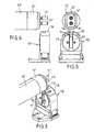
- a lamp socket is generally designated 10.
- This is a fluorescent lamp socket of conventional design, as shown and described for example in EP 0 735 630 B1.
- Such a socket serves to receive two contact pins 11, which are located on the base 12 of a double-ended fluorescent lamp 13.
- the socket 10 has a gap arrangement 14/15, wherein the gap 14 extends at the zenith of the head 16 of the socket body 10 and the gap 15 with respect to the figures vertically downward on the side facing the lamp 13.
- the gap 15 extends through the rotor 17 therethrough.
- Fig. 1 shows the state of the art, namely the pairing of a conventional fluorescent lamp 13 with standardized base pins 11 and a socket 10 with a standardized gap arrangement 14/15.
- the widths of the gaps 14 and 15 are slightly larger than the diameter of the cylindrical base pins 11.
- an adapter 18 is provided, which - as the overview. 2 shows, on the head 16 of the socket 10 can be placed.
- the adapter may be e.g. be welded or glued to the head portion of the socket.
- the adapter 18 has a gap 19 which is in correctly placed on the head 16 of the socket 10 adapter 18 with the wider gap 14 in the socket body 10 in registration.
- the gap width of the gap 19 is less than the diameter of the Base pins 11, which consequently can not be used in the version 10.
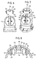
- Fig. 3 shows a fluorescent lamp 13 '
- the base 12' are equipped with lamp contacts 11 ', at least in the direction transverse to the gap assembly 14/15 to a lesser extent than the diameter of the base pins 11 conventional fluorescent lamps 13.
- the base pins 11 ' are tube-shaped and pressed flat accordingly.
- a fluorescent lamp 13 'equipped with such base pins 11' can pass through the narrowed gap 19 in the adapter 18. Consequently, the fluorescent lamp 13 'can be used in a conventional lamp socket 10, even if it is equipped with the gap-narrowed adapter 18.
- the adapter 18 is a plastic injection-molded part, which is preferably colored differently than the socket 10 in order to achieve a signal effect in this way ..
- the component is rounded in accordance with the curvature of the head 16 of the lamp holder 10, so that the adapter with its approximately cup-shaped body can sit fully on the outside of the socket head 16.
- On the inside of the adapter 18 are two mutually parallel extensions or projections 20 with end-side detent hooks 21. These are intended to pass through openings 22, which are located in the head region of the socket 10.
- These openings 22 are openings for introducing test probes for the so-called "top test", as explained in detail in the aforementioned EP 0 735 630 B1, so that reference is made to this document with regard to further details in this regard ,
- the projections 20 pass through the openings 22 when placing the adapter 18 on the head 16 of the socket 10, and the latching hooks 21 snap behind the inner edges 23 of the openings 22.
- Such an adapter 18 can thus be with the aid of a simple positive locking connection with a conventional , do not connect modified version 10 in any way.
- the edges of the gap 19 located in the adapter are bounded by two webs 24, which, opposite one another, engage in the mouth of the gap 14 of the holder 10.
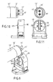
- FIGS. 9 to 11 An alternative solution is shown in FIGS. 9 to 11, which differs from the one described above in that, instead of a special adapter 18, a special rotor 17 'assumes an adapter function.
- the arrangement is such that the width 25 of the rotor 17 'located in the gap is less than in a rotor, as it is available for a originally determined version.
- the gap width 25 is smaller than the diameter of conventional socket pins 11.
- it is slightly wider than the measured in the same direction narrow width of the socket pins 11 'of a new fluorescent lamp 13'. This can therefore be introduced in the usual way in the version 10 and spent after turning into its electrical operating position.
- the rotor 17 ' is colored in a different color than a belonging to the socket 10 common rotor and possibly also in a different color than the socket housing 10, so that it is immediately apparent for which purpose determines the appropriately equipped socket is.
- a conventional fluorescent lamp 13 can be used with sockets 11 in the socket 10 of conventional design, when either a simple adapter 18 is attached to the socket body 10 or the version 10 is equipped with a special rotor 17 '.
Landscapes
- Fastening Of Light Sources Or Lamp Holders (AREA)
- Connecting Device With Holders (AREA)
Applications Claiming Priority (2)
| Application Number | Priority Date | Filing Date | Title |
|---|---|---|---|
| DE102004011635 | 2004-03-10 | ||
| DE102004011635A DE102004011635A1 (de) | 2004-03-10 | 2004-03-10 | Fassung für zweiseitig gesockelte röhrenförmige Leuchtstofflampen mit Zweistift-Sockeln |
Publications (2)
| Publication Number | Publication Date |
|---|---|
| EP1577989A1 EP1577989A1 (de) | 2005-09-21 |
| EP1577989B1 true EP1577989B1 (de) | 2007-02-28 |
Family
ID=34833110
Family Applications (1)
| Application Number | Title | Priority Date | Filing Date |
|---|---|---|---|
| EP05000766A Not-in-force EP1577989B1 (de) | 2004-03-10 | 2005-01-15 | Fassung für zweiseitig gesockelte röhrenförmige Leuchtstofflampen mit Zweistift-Sockeln |
Country Status (7)
| Country | Link |
|---|---|
| US (2) | US7153151B2 (ja) |
| EP (1) | EP1577989B1 (ja) |
| JP (1) | JP2005317527A (ja) |
| CN (1) | CN100468885C (ja) |
| AT (1) | ATE355639T1 (ja) |
| DE (2) | DE102004011635A1 (ja) |
| ES (1) | ES2281030T3 (ja) |
Families Citing this family (20)
| Publication number | Priority date | Publication date | Assignee | Title |
|---|---|---|---|---|
| CA2605182A1 (en) * | 2005-04-18 | 2006-10-26 | Leviton Manufacturing Co., Inc. | T-8 to t-5 adapter lampholder |
| DE102005021596B4 (de) * | 2005-05-10 | 2016-09-22 | Osram Gmbh | Lampensockel mit Farbcodierung und Lampe mit einem Lampensockel |
| US7597575B2 (en) | 2005-09-13 | 2009-10-06 | Leviton Manufacturing Co., Inc. | Fluorescent lampholder |
| EP1958227B1 (en) * | 2005-11-22 | 2018-08-01 | Trojan Technologies Inc. | Radiation lamp and radiation source module incorporating same |
| US7806710B2 (en) * | 2007-02-27 | 2010-10-05 | Samsung Electronics Co., Ltd. | Lamp holding unit |
| US7927154B2 (en) * | 2008-05-12 | 2011-04-19 | GE Lighting Solutions, LLC | Bi-pin connector and a lamp employing the same |
| WO2010005682A2 (en) * | 2008-06-12 | 2010-01-14 | Light Sources, Inc. | End cap, socket, and adaptors for use with a lamp |
| WO2010001650A1 (ja) * | 2008-07-02 | 2010-01-07 | シャープ株式会社 | 光源装置及び表示装置 |
| US8113684B2 (en) | 2008-07-15 | 2012-02-14 | Leviton Manufacturing Co., Inc. | Fluorescent lamp support |
| US20100265700A1 (en) * | 2008-07-15 | 2010-10-21 | Leviton Manufacturing Corporation | Flourescent lamp support |
| US20110164414A1 (en) * | 2008-07-15 | 2011-07-07 | Robert Quercia | Fluorescent lamp support |
| US20110081806A1 (en) * | 2008-07-29 | 2011-04-07 | Li-Hua Lin | Lamp Tube Adapter Structure for Lighting Apparatus |
| KR200452646Y1 (ko) | 2008-09-09 | 2011-03-14 | 최옥판 | 전등핀 |
| US20100081339A1 (en) | 2008-10-01 | 2010-04-01 | Leviton Manufacturing Company, Inc. | Lamp socket having a rotor assembly |
| US7963661B2 (en) * | 2009-02-09 | 2011-06-21 | American Greetings Corporation | Display light fixtures |
| US9318860B2 (en) * | 2010-03-23 | 2016-04-19 | Panasonic Corporation | Light source, lamp socket and illumination device using the lamp socket |
| EP2587115B1 (en) * | 2010-06-28 | 2018-09-26 | Panasonic Corporation | Straight tube led lamp, lamp socket set, and illumination equipment |
| US8333602B2 (en) | 2011-01-06 | 2012-12-18 | Leviton Manufacturing Co., Inc. | Lamp socket having a rotor |
| USD727849S1 (en) * | 2013-02-08 | 2015-04-28 | Panasonic Intellectual Property Management Co., Ltd. | Socket for light-emitting diode lamp |
| USD797050S1 (en) * | 2016-02-19 | 2017-09-12 | Dinesh Wadhwani | Socket |
Family Cites Families (5)
| Publication number | Priority date | Publication date | Assignee | Title |
|---|---|---|---|---|
| US2324683A (en) * | 1940-11-20 | 1943-07-20 | Pass & Seymour Inc | Socket for fluorescent lamps |
| US3975073A (en) * | 1971-12-02 | 1976-08-17 | Westinghouse Electric Corporation | Fluorescent lampholder with means for circuit interruption |
| DE19511887C1 (de) * | 1995-03-31 | 1996-07-11 | Broekelmann Jaeger & Busse | Lampenfassung, insbesondere für Leuchtstofflampen |
| US6234829B1 (en) * | 1999-03-25 | 2001-05-22 | International Business Machines Corporation | Method and device for identifying card slots that are required to be populated concurrently in a computer system |
| DE10119081B4 (de) * | 2001-04-19 | 2004-11-11 | Vossloh-Schwabe Deutschland Gmbh | Fassung für Lampen mit Zweistiftsockel |
-
2004
- 2004-03-10 DE DE102004011635A patent/DE102004011635A1/de not_active Withdrawn
-
2005
- 2005-01-15 DE DE502005000405T patent/DE502005000405D1/de active Active
- 2005-01-15 AT AT05000766T patent/ATE355639T1/de not_active IP Right Cessation
- 2005-01-15 EP EP05000766A patent/EP1577989B1/de not_active Not-in-force
- 2005-01-15 ES ES05000766T patent/ES2281030T3/es active Active
- 2005-02-28 US US11/069,571 patent/US7153151B2/en not_active Expired - Fee Related
- 2005-03-04 JP JP2005104065A patent/JP2005317527A/ja active Pending
- 2005-03-09 CN CNB2005100527222A patent/CN100468885C/zh not_active Expired - Fee Related
-
2006
- 2006-12-05 US US11/634,228 patent/US7247040B2/en not_active Expired - Fee Related
Also Published As
| Publication number | Publication date |
|---|---|
| ES2281030T3 (es) | 2007-09-16 |
| US20050202704A1 (en) | 2005-09-15 |
| ATE355639T1 (de) | 2006-03-15 |
| CN1667888A (zh) | 2005-09-14 |
| US7247040B2 (en) | 2007-07-24 |
| CN100468885C (zh) | 2009-03-11 |
| EP1577989A1 (de) | 2005-09-21 |
| DE502005000405D1 (de) | 2007-04-12 |
| JP2005317527A (ja) | 2005-11-10 |
| US20070077801A1 (en) | 2007-04-05 |
| US7153151B2 (en) | 2006-12-26 |
| DE102004011635A1 (de) | 2005-10-06 |
Similar Documents
| Publication | Publication Date | Title |
|---|---|---|
| EP1577989B1 (de) | Fassung für zweiseitig gesockelte röhrenförmige Leuchtstofflampen mit Zweistift-Sockeln | |
| EP0283087B1 (de) | Lampe für eine stabförmige Leuchtstofflampe | |
| EP1989724B1 (de) | Lampensockel und lampe mit einem lampensockel | |
| DE661023C (de) | Loesbares Kupplungsschloss, insbesondere Steckvorrichtung fuer elektrische oder mechanische Zwecke | |
| EP1037245A2 (de) | Strahlereinheit aus beidseitig gesockelter Entladungslampe und Lampen-Fassung | |
| DE19640882B4 (de) | Fassung für Leuchtstofflampen | |
| EP2337061A1 (de) | Elektrische Lampe mit einem Außenkolben, einem Tellerfuß und einer Einbaulampe | |
| DE10119081B4 (de) | Fassung für Lampen mit Zweistiftsockel | |
| DE19521735C2 (de) | Steckelement zum Befestigen und Anschließen einer Lampe | |
| DE4329757B4 (de) | Steckdose für elektrischen Strom | |
| DE3816909A1 (de) | In einer einbauoeffnung einer kfz.-leuchte befestigbare lampenfassung aus kunststoff | |
| DE102004056011B4 (de) | Lampenfassung | |
| DE202004003735U1 (de) | Fassung für zweiseitig gesockelte röhrenförmige Leuchtstofflampen mit Zweistift-Sockeln | |
| DE19615373C2 (de) | Fassung, insbesondere für stabförmige Leuchtstoffröhren | |
| DE10117570A1 (de) | Elektrischer Kontakt sowie Lampenfassung und Anschluss- oder Verbindungsklemme mit mindestens einem solchen Kontakt | |
| EP1467448B1 (de) | Steckeradapter, insbesondere zum Anschluss von Lampen | |
| DE4219068C2 (de) | Fassung für Leuchtstofflampen | |
| DE19854440A1 (de) | Verlängerungsstück für Leuchtstofflampen | |
| DE3908618C2 (ja) | ||
| DE2445292C2 (de) | Leuchte | |
| DE3638508C2 (ja) | ||
| EP2453170B1 (de) | Befestigungsvorrichtung für Sensoren an Leuchten | |
| EP0214424B1 (de) | Fassung für eine elektrische Glühlampe mit Bajonettsockel | |
| EP1819020B1 (de) | Lampenfassung | |
| DE3638507A1 (de) | Explosions- bzw. schlagwettergeschuetzte leuchtstofflampe |
Legal Events
| Date | Code | Title | Description |
|---|---|---|---|
| PUAI | Public reference made under article 153(3) epc to a published international application that has entered the european phase |
Free format text: ORIGINAL CODE: 0009012 |
|
| 17P | Request for examination filed |
Effective date: 20050708 |
|
| AK | Designated contracting states |
Kind code of ref document: A1 Designated state(s): AT BE BG CH CY CZ DE DK EE ES FI FR GB GR HU IE IS IT LI LT LU MC NL PL PT RO SE SI SK TR |
|
| AX | Request for extension of the european patent |
Extension state: AL BA HR LV MK YU |
|
| AKX | Designation fees paid |
Designated state(s): AT BE BG CH CY CZ DE DK EE ES FI FR GB GR HU IE IS IT LI LT LU MC NL PL PT RO SE SI SK TR |
|
| GRAP | Despatch of communication of intention to grant a patent |
Free format text: ORIGINAL CODE: EPIDOSNIGR1 |
|
| 17Q | First examination report despatched |
Effective date: 20051027 |
|
| GRAS | Grant fee paid |
Free format text: ORIGINAL CODE: EPIDOSNIGR3 |
|
| GRAA | (expected) grant |
Free format text: ORIGINAL CODE: 0009210 |
|
| AK | Designated contracting states |
Kind code of ref document: B1 Designated state(s): AT BE BG CH CY CZ DE DK EE ES FI FR GB GR HU IE IS IT LI LT LU MC NL PL PT RO SE SI SK TR |
|
| PG25 | Lapsed in a contracting state [announced via postgrant information from national office to epo] |
Ref country code: SI Free format text: LAPSE BECAUSE OF FAILURE TO SUBMIT A TRANSLATION OF THE DESCRIPTION OR TO PAY THE FEE WITHIN THE PRESCRIBED TIME-LIMIT Effective date: 20070228 Ref country code: IE Free format text: LAPSE BECAUSE OF FAILURE TO SUBMIT A TRANSLATION OF THE DESCRIPTION OR TO PAY THE FEE WITHIN THE PRESCRIBED TIME-LIMIT Effective date: 20070228 Ref country code: PL Free format text: LAPSE BECAUSE OF FAILURE TO SUBMIT A TRANSLATION OF THE DESCRIPTION OR TO PAY THE FEE WITHIN THE PRESCRIBED TIME-LIMIT Effective date: 20070228 Ref country code: DK Free format text: LAPSE BECAUSE OF FAILURE TO SUBMIT A TRANSLATION OF THE DESCRIPTION OR TO PAY THE FEE WITHIN THE PRESCRIBED TIME-LIMIT Effective date: 20070228 |
|
| REG | Reference to a national code |
Ref country code: GB Ref legal event code: FG4D Free format text: NOT ENGLISH |
|
| GBT | Gb: translation of ep patent filed (gb section 77(6)(a)/1977) |
Effective date: 20070228 |
|
| REG | Reference to a national code |
Ref country code: CH Ref legal event code: EP |
|
| REF | Corresponds to: |
Ref document number: 502005000405 Country of ref document: DE Date of ref document: 20070412 Kind code of ref document: P |
|
| REG | Reference to a national code |
Ref country code: IE Ref legal event code: FG4D Free format text: LANGUAGE OF EP DOCUMENT: GERMAN |
|
| REG | Reference to a national code |
Ref country code: SE Ref legal event code: TRGR |
|
| PG25 | Lapsed in a contracting state [announced via postgrant information from national office to epo] |
Ref country code: BG Free format text: LAPSE BECAUSE OF FAILURE TO SUBMIT A TRANSLATION OF THE DESCRIPTION OR TO PAY THE FEE WITHIN THE PRESCRIBED TIME-LIMIT Effective date: 20070528 |
|
| PG25 | Lapsed in a contracting state [announced via postgrant information from national office to epo] |
Ref country code: IS Free format text: LAPSE BECAUSE OF FAILURE TO SUBMIT A TRANSLATION OF THE DESCRIPTION OR TO PAY THE FEE WITHIN THE PRESCRIBED TIME-LIMIT Effective date: 20070628 |
|
| ET | Fr: translation filed | ||
| PG25 | Lapsed in a contracting state [announced via postgrant information from national office to epo] |
Ref country code: PT Free format text: LAPSE BECAUSE OF FAILURE TO SUBMIT A TRANSLATION OF THE DESCRIPTION OR TO PAY THE FEE WITHIN THE PRESCRIBED TIME-LIMIT Effective date: 20070730 |
|
| REG | Reference to a national code |
Ref country code: ES Ref legal event code: FG2A Ref document number: 2281030 Country of ref document: ES Kind code of ref document: T3 |
|
| REG | Reference to a national code |
Ref country code: IE Ref legal event code: FD4D |
|
| PG25 | Lapsed in a contracting state [announced via postgrant information from national office to epo] |
Ref country code: SK Free format text: LAPSE BECAUSE OF FAILURE TO SUBMIT A TRANSLATION OF THE DESCRIPTION OR TO PAY THE FEE WITHIN THE PRESCRIBED TIME-LIMIT Effective date: 20070228 |
|
| PG25 | Lapsed in a contracting state [announced via postgrant information from national office to epo] |
Ref country code: CZ Free format text: LAPSE BECAUSE OF FAILURE TO SUBMIT A TRANSLATION OF THE DESCRIPTION OR TO PAY THE FEE WITHIN THE PRESCRIBED TIME-LIMIT Effective date: 20070228 Ref country code: RO Free format text: LAPSE BECAUSE OF FAILURE TO SUBMIT A TRANSLATION OF THE DESCRIPTION OR TO PAY THE FEE WITHIN THE PRESCRIBED TIME-LIMIT Effective date: 20070228 |
|
| PLBE | No opposition filed within time limit |
Free format text: ORIGINAL CODE: 0009261 |
|
| STAA | Information on the status of an ep patent application or granted ep patent |
Free format text: STATUS: NO OPPOSITION FILED WITHIN TIME LIMIT |
|
| 26N | No opposition filed |
Effective date: 20071129 |
|
| PG25 | Lapsed in a contracting state [announced via postgrant information from national office to epo] |
Ref country code: LT Free format text: LAPSE BECAUSE OF FAILURE TO SUBMIT A TRANSLATION OF THE DESCRIPTION OR TO PAY THE FEE WITHIN THE PRESCRIBED TIME-LIMIT Effective date: 20070228 |
|
| PG25 | Lapsed in a contracting state [announced via postgrant information from national office to epo] |
Ref country code: GR Free format text: LAPSE BECAUSE OF FAILURE TO SUBMIT A TRANSLATION OF THE DESCRIPTION OR TO PAY THE FEE WITHIN THE PRESCRIBED TIME-LIMIT Effective date: 20070529 |
|
| BERE | Be: lapsed |
Owner name: BJB G.M.B.H. & CO. KG Effective date: 20080131 |
|
| PG25 | Lapsed in a contracting state [announced via postgrant information from national office to epo] |
Ref country code: MC Free format text: LAPSE BECAUSE OF NON-PAYMENT OF DUE FEES Effective date: 20080131 |
|
| PG25 | Lapsed in a contracting state [announced via postgrant information from national office to epo] |
Ref country code: EE Free format text: LAPSE BECAUSE OF FAILURE TO SUBMIT A TRANSLATION OF THE DESCRIPTION OR TO PAY THE FEE WITHIN THE PRESCRIBED TIME-LIMIT Effective date: 20070228 |
|
| PG25 | Lapsed in a contracting state [announced via postgrant information from national office to epo] |
Ref country code: BE Free format text: LAPSE BECAUSE OF NON-PAYMENT OF DUE FEES Effective date: 20080131 |
|
| PG25 | Lapsed in a contracting state [announced via postgrant information from national office to epo] |
Ref country code: AT Free format text: LAPSE BECAUSE OF NON-PAYMENT OF DUE FEES Effective date: 20080115 |
|
| PG25 | Lapsed in a contracting state [announced via postgrant information from national office to epo] |
Ref country code: CY Free format text: LAPSE BECAUSE OF FAILURE TO SUBMIT A TRANSLATION OF THE DESCRIPTION OR TO PAY THE FEE WITHIN THE PRESCRIBED TIME-LIMIT Effective date: 20070228 |
|
| REG | Reference to a national code |
Ref country code: CH Ref legal event code: PL |
|
| PG25 | Lapsed in a contracting state [announced via postgrant information from national office to epo] |
Ref country code: LI Free format text: LAPSE BECAUSE OF NON-PAYMENT OF DUE FEES Effective date: 20090131 Ref country code: CH Free format text: LAPSE BECAUSE OF NON-PAYMENT OF DUE FEES Effective date: 20090131 |
|
| PG25 | Lapsed in a contracting state [announced via postgrant information from national office to epo] |
Ref country code: LU Free format text: LAPSE BECAUSE OF NON-PAYMENT OF DUE FEES Effective date: 20080115 Ref country code: HU Free format text: LAPSE BECAUSE OF FAILURE TO SUBMIT A TRANSLATION OF THE DESCRIPTION OR TO PAY THE FEE WITHIN THE PRESCRIBED TIME-LIMIT Effective date: 20070901 |
|
| PG25 | Lapsed in a contracting state [announced via postgrant information from national office to epo] |
Ref country code: TR Free format text: LAPSE BECAUSE OF FAILURE TO SUBMIT A TRANSLATION OF THE DESCRIPTION OR TO PAY THE FEE WITHIN THE PRESCRIBED TIME-LIMIT Effective date: 20070228 |
|
| PGFP | Annual fee paid to national office [announced via postgrant information from national office to epo] |
Ref country code: FR Payment date: 20120213 Year of fee payment: 8 |
|
| REG | Reference to a national code |
Ref country code: DE Ref legal event code: R082 Ref document number: 502005000405 Country of ref document: DE Representative=s name: PATENTANWAELTE OSTRIGA, SONNET, WIRTHS & VORWE, DE |
|
| PGFP | Annual fee paid to national office [announced via postgrant information from national office to epo] |
Ref country code: FI Payment date: 20120109 Year of fee payment: 8 Ref country code: SE Payment date: 20120124 Year of fee payment: 8 Ref country code: GB Payment date: 20120103 Year of fee payment: 8 |
|
| PGFP | Annual fee paid to national office [announced via postgrant information from national office to epo] |
Ref country code: NL Payment date: 20120130 Year of fee payment: 8 |
|
| PGFP | Annual fee paid to national office [announced via postgrant information from national office to epo] |
Ref country code: ES Payment date: 20120124 Year of fee payment: 8 |
|
| REG | Reference to a national code |
Ref country code: NL Ref legal event code: V1 Effective date: 20130801 |
|
| REG | Reference to a national code |
Ref country code: SE Ref legal event code: EUG |
|
| GBPC | Gb: european patent ceased through non-payment of renewal fee |
Effective date: 20130115 |
|
| REG | Reference to a national code |
Ref country code: FR Ref legal event code: ST Effective date: 20130930 |
|
| PG25 | Lapsed in a contracting state [announced via postgrant information from national office to epo] |
Ref country code: FI Free format text: LAPSE BECAUSE OF NON-PAYMENT OF DUE FEES Effective date: 20130115 Ref country code: NL Free format text: LAPSE BECAUSE OF NON-PAYMENT OF DUE FEES Effective date: 20130801 Ref country code: SE Free format text: LAPSE BECAUSE OF NON-PAYMENT OF DUE FEES Effective date: 20130116 |
|
| PG25 | Lapsed in a contracting state [announced via postgrant information from national office to epo] |
Ref country code: GB Free format text: LAPSE BECAUSE OF NON-PAYMENT OF DUE FEES Effective date: 20130115 Ref country code: FR Free format text: LAPSE BECAUSE OF NON-PAYMENT OF DUE FEES Effective date: 20130131 |
|
| REG | Reference to a national code |
Ref country code: ES Ref legal event code: FD2A Effective date: 20140321 |
|
| PG25 | Lapsed in a contracting state [announced via postgrant information from national office to epo] |
Ref country code: ES Free format text: LAPSE BECAUSE OF NON-PAYMENT OF DUE FEES Effective date: 20130116 |
|
| PGFP | Annual fee paid to national office [announced via postgrant information from national office to epo] |
Ref country code: IT Payment date: 20190121 Year of fee payment: 15 Ref country code: DE Payment date: 20181127 Year of fee payment: 15 |
|
| REG | Reference to a national code |
Ref country code: DE Ref legal event code: R119 Ref document number: 502005000405 Country of ref document: DE |
|
| PG25 | Lapsed in a contracting state [announced via postgrant information from national office to epo] |
Ref country code: DE Free format text: LAPSE BECAUSE OF NON-PAYMENT OF DUE FEES Effective date: 20200801 |
|
| PG25 | Lapsed in a contracting state [announced via postgrant information from national office to epo] |
Ref country code: IT Free format text: LAPSE BECAUSE OF NON-PAYMENT OF DUE FEES Effective date: 20200115 |