EP1577989B1 - Socket for tubular fluorescent lamps with two-pin bases on both sides - Google Patents
Socket for tubular fluorescent lamps with two-pin bases on both sides Download PDFInfo
- Publication number
- EP1577989B1 EP1577989B1 EP05000766A EP05000766A EP1577989B1 EP 1577989 B1 EP1577989 B1 EP 1577989B1 EP 05000766 A EP05000766 A EP 05000766A EP 05000766 A EP05000766 A EP 05000766A EP 1577989 B1 EP1577989 B1 EP 1577989B1
- Authority
- EP
- European Patent Office
- Prior art keywords
- socket
- slot
- adapter
- lead
- lamp
- Prior art date
- Legal status (The legal status is an assumption and is not a legal conclusion. Google has not performed a legal analysis and makes no representation as to the accuracy of the status listed.)
- Not-in-force
Links
Images

Classifications
-
- H—ELECTRICITY
- H01—ELECTRIC ELEMENTS
- H01R—ELECTRICALLY-CONDUCTIVE CONNECTIONS; STRUCTURAL ASSOCIATIONS OF A PLURALITY OF MUTUALLY-INSULATED ELECTRICAL CONNECTING ELEMENTS; COUPLING DEVICES; CURRENT COLLECTORS
- H01R33/00—Coupling devices specially adapted for supporting apparatus and having one part acting as a holder providing support and electrical connection via a counterpart which is structurally associated with the apparatus, e.g. lamp holders; Separate parts thereof
- H01R33/05—Two-pole devices
- H01R33/06—Two-pole devices with two current-carrying pins, blades or analogous contacts, having their axes parallel to each other
- H01R33/08—Two-pole devices with two current-carrying pins, blades or analogous contacts, having their axes parallel to each other for supporting tubular fluorescent lamp
- H01R33/0836—Two-pole devices with two current-carrying pins, blades or analogous contacts, having their axes parallel to each other for supporting tubular fluorescent lamp characterised by the lamp holding means
- H01R33/0854—Two-pole devices with two current-carrying pins, blades or analogous contacts, having their axes parallel to each other for supporting tubular fluorescent lamp characterised by the lamp holding means with lamp rotating means
-
- H—ELECTRICITY
- H01—ELECTRIC ELEMENTS
- H01R—ELECTRICALLY-CONDUCTIVE CONNECTIONS; STRUCTURAL ASSOCIATIONS OF A PLURALITY OF MUTUALLY-INSULATED ELECTRICAL CONNECTING ELEMENTS; COUPLING DEVICES; CURRENT COLLECTORS
- H01R33/00—Coupling devices specially adapted for supporting apparatus and having one part acting as a holder providing support and electrical connection via a counterpart which is structurally associated with the apparatus, e.g. lamp holders; Separate parts thereof
- H01R33/05—Two-pole devices
- H01R33/06—Two-pole devices with two current-carrying pins, blades or analogous contacts, having their axes parallel to each other
- H01R33/08—Two-pole devices with two current-carrying pins, blades or analogous contacts, having their axes parallel to each other for supporting tubular fluorescent lamp
- H01R33/0836—Two-pole devices with two current-carrying pins, blades or analogous contacts, having their axes parallel to each other for supporting tubular fluorescent lamp characterised by the lamp holding means
-
- H—ELECTRICITY
- H01—ELECTRIC ELEMENTS
- H01R—ELECTRICALLY-CONDUCTIVE CONNECTIONS; STRUCTURAL ASSOCIATIONS OF A PLURALITY OF MUTUALLY-INSULATED ELECTRICAL CONNECTING ELEMENTS; COUPLING DEVICES; CURRENT COLLECTORS
- H01R33/00—Coupling devices specially adapted for supporting apparatus and having one part acting as a holder providing support and electrical connection via a counterpart which is structurally associated with the apparatus, e.g. lamp holders; Separate parts thereof
- H01R33/90—Coupling devices specially adapted for supporting apparatus and having one part acting as a holder providing support and electrical connection via a counterpart which is structurally associated with the apparatus, e.g. lamp holders; Separate parts thereof adapted for co-operation with two or more dissimilar counterparts
Definitions
- the invention relates to a socket for double-capped tubular fluorescent lamps with two-pin sockets of a given standard, e.g. the size G5, with contacts for contacting the lamp-side standardized socket pins and with an insertion gap arrangement for use of the socket pins in the socket, wherein a first insertion gap extends on the side facing the lamp and a second insertion gap in a head portion of the socket housing transversely thereto, wherein the width of the first and second slots is slightly larger than the diameter of the standardized socket pins,
- Fluorescent lamps require their operation in a lamp, which is equipped with these lamps, in addition to Startem so-called ballasts, which generate the necessary for the operation of the lamps of a lamp ignition voltage. These are specially adapted to the special lamps or lamp classes. This means that you can not arbitrarily operate a lamp containing any particular ballast with any fluorescent lamps without the risk that the electrical equipment or the lamp could be destroyed.
- US-A-2 324 683 discloses a generic socket according to the preamble of independent claim 1. It has a first lead-in gap on the socket-side facing the lamp and a second lead-in gap in a head portion of the socket housing extending transversely thereto. In this second insertion gap, a blocking piece can be used to close the insertion gap against entry or exit of the base pins of the fluorescent tube.
- EP-A-1 251 603 describes a generic socket according to the preamble of independent claim 11 and accordingly a conventional rotor socket with a rotor adapted in its width to the pin width of the fluorescent tube to be used.
- the present invention is based on the consideration that in the future fluorescent lamps could be developed that require specially adapted ballasts, with which the conventional fluorescent lamps can not stand. If new luminaires are equipped with new ballasts, it must be effectively prevented that these luminaires are equipped with conventional lamps. This represents a considerable problem in practice, especially if the conventional as well as the new fluorescent lamps should have substantially the same base pitches and the same geometric base data, in particular with regard to the length of the base pins and their spacing from one another.
- a socket family includes numerous versions of a design with numerous designs, in particular with regard to their attachment means for attachment to the lamp housing.
- the invention solves this problem on the one hand with the features of independent claim 1 and is characterized by a connectable to the head portion of the socket housing, the second insertion gap at least partially narrowing adapter such that only socket pins can be inserted into the second insertion gap, the slimmer are the standardized socket pins for which the socket is originally designed.
- the base pins of the new lamp are made narrower than the conventional base pins, at least in the direction transverse to their direction of insertion into the socket. In tube-shaped lamp contact pins this can be done for example by light flattening.
- the shape of the adapter is suitably adapted to that of the head portion of the socket housing.
- the adapter to the socket housing - if necessary camelösbar - be fixable by means of locking hooks.
- a particularly advantageous solution consists in a version whose socket housing openings as so-called. "Top test openings", in that the adapter has projections which can be latched in the openings and thereby lock the adapter to the socket housing.
- the extensions are frictionally engaged, e.g. by means of press fit, anchored in the openings.
- the adapter can be attached to the socket housing with a simple plug-in connection, but if necessary also loosen it again with the aid of a tool.
- the adapter to the head portion of the socket body, e.g. by welding or gluing, firm and insoluble, i. so permanently, to connect.
- an advantageous embodiment is that the adapter is provided with an insertion gap for lamp contact pins, which is defined between two webs, which in the introduction gap of the socket housing, this narrowing immersed.
- the adapter may be formed as a thin-walled, adapted to the curvature of the head portion of the socket housing shell. On the one hand, this reduces the cost of materials for the adapter to the bare minimum; On the other hand, this shape adapts optimally to that of the socket body, which also brings aesthetic benefits.
- an advantageous further feature of the invention is that the adapter has a different color from the color of the socket housing.
- the adapter receives a signal effect and function, which allows the person skilled in the art to immediately recognize which technology is to be assigned to the socket equipped with this adapter.
- the invention solves the problem initially posed in a rotor socket for double-ended tubular fluorescent lamps with two-pin sockets of a given standard, eg the size G5, with contacts for contacting the lamp-side standardized socket pins and with an insertion gap arrangement for use of the socket pins in the socket, wherein a first insertion gap is formed on the lamp-facing socket side in a rotor and a second insertion gap extending transversely in a head portion of the socket housing, the width of the second Insertion gap is slightly larger than the diameter of the standardized socket pins, with the characterizing features of independent claim 11, characterized in that the rotor formed in the first insertion gap has a smaller width than the second insertion gap in the socket, so that introduced in the first insertion gap only socket pins which are slimmer than the standardized socket pins for which the socket is originally intended.
- a signaling marking is advantageous in that the rotor has a color deviating from the color of conventional rotors and possibly also the color of the socket housing.
- a lamp socket is generally designated 10.
- This is a fluorescent lamp socket of conventional design, as shown and described for example in EP 0 735 630 B1.
- Such a socket serves to receive two contact pins 11, which are located on the base 12 of a double-ended fluorescent lamp 13.
- the socket 10 has a gap arrangement 14/15, wherein the gap 14 extends at the zenith of the head 16 of the socket body 10 and the gap 15 with respect to the figures vertically downward on the side facing the lamp 13.
- the gap 15 extends through the rotor 17 therethrough.
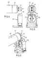
- Fig. 1 shows the state of the art, namely the pairing of a conventional fluorescent lamp 13 with standardized base pins 11 and a socket 10 with a standardized gap arrangement 14/15.
- the widths of the gaps 14 and 15 are slightly larger than the diameter of the cylindrical base pins 11.
- an adapter 18 is provided, which - as the overview. 2 shows, on the head 16 of the socket 10 can be placed.
- the adapter may be e.g. be welded or glued to the head portion of the socket.
- the adapter 18 has a gap 19 which is in correctly placed on the head 16 of the socket 10 adapter 18 with the wider gap 14 in the socket body 10 in registration.
- the gap width of the gap 19 is less than the diameter of the Base pins 11, which consequently can not be used in the version 10.
- Fig. 3 shows a fluorescent lamp 13 '
- the base 12' are equipped with lamp contacts 11 ', at least in the direction transverse to the gap assembly 14/15 to a lesser extent than the diameter of the base pins 11 conventional fluorescent lamps 13.
- the base pins 11 ' are tube-shaped and pressed flat accordingly.
- a fluorescent lamp 13 'equipped with such base pins 11' can pass through the narrowed gap 19 in the adapter 18. Consequently, the fluorescent lamp 13 'can be used in a conventional lamp socket 10, even if it is equipped with the gap-narrowed adapter 18.
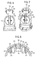
- the adapter 18 is a plastic injection-molded part, which is preferably colored differently than the socket 10 in order to achieve a signal effect in this way ..
- the component is rounded in accordance with the curvature of the head 16 of the lamp holder 10, so that the adapter with its approximately cup-shaped body can sit fully on the outside of the socket head 16.
- On the inside of the adapter 18 are two mutually parallel extensions or projections 20 with end-side detent hooks 21. These are intended to pass through openings 22, which are located in the head region of the socket 10.
- These openings 22 are openings for introducing test probes for the so-called "top test", as explained in detail in the aforementioned EP 0 735 630 B1, so that reference is made to this document with regard to further details in this regard ,
- the projections 20 pass through the openings 22 when placing the adapter 18 on the head 16 of the socket 10, and the latching hooks 21 snap behind the inner edges 23 of the openings 22.
- Such an adapter 18 can thus be with the aid of a simple positive locking connection with a conventional , do not connect modified version 10 in any way.
- the edges of the gap 19 located in the adapter are bounded by two webs 24, which, opposite one another, engage in the mouth of the gap 14 of the holder 10.
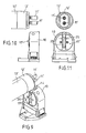
- FIGS. 9 to 11 An alternative solution is shown in FIGS. 9 to 11, which differs from the one described above in that, instead of a special adapter 18, a special rotor 17 'assumes an adapter function.
- the arrangement is such that the width 25 of the rotor 17 'located in the gap is less than in a rotor, as it is available for a originally determined version.
- the gap width 25 is smaller than the diameter of conventional socket pins 11.
- it is slightly wider than the measured in the same direction narrow width of the socket pins 11 'of a new fluorescent lamp 13'. This can therefore be introduced in the usual way in the version 10 and spent after turning into its electrical operating position.
- the rotor 17 ' is colored in a different color than a belonging to the socket 10 common rotor and possibly also in a different color than the socket housing 10, so that it is immediately apparent for which purpose determines the appropriately equipped socket is.
- a conventional fluorescent lamp 13 can be used with sockets 11 in the socket 10 of conventional design, when either a simple adapter 18 is attached to the socket body 10 or the version 10 is equipped with a special rotor 17 '.
Landscapes
- Fastening Of Light Sources Or Lamp Holders (AREA)
- Connecting Device With Holders (AREA)
Abstract
Description
Die Erfindung bezieht sich auf eine Fassung für zweiseitig gesockelte röhrenförmige Leuchtstofflampen mit Zweistift-Sockeln eines vorgegebenen Standards, z.B. der Größe G5, mit Kontakten zur Kontaktierung der lampenseitigen standardisierten Sockelstifte und mit einer Einführungsspalt-Anordnung zum Einsatz der Sockelstifte in die Fassung, wobei sich ein erster Einführungsspalt auf der zur Lampe weisenden Fassungsseite sowie ein zweiter Einführungsspalt in einem Kopfbereich des Fassungsgehäuses quer dazu erstreckt, wobei die Weite der ersten und zweiten Spalte geringfügig größer als der Durchmesser der standardisierten Sockelstifte ist,The invention relates to a socket for double-capped tubular fluorescent lamps with two-pin sockets of a given standard, e.g. the size G5, with contacts for contacting the lamp-side standardized socket pins and with an insertion gap arrangement for use of the socket pins in the socket, wherein a first insertion gap extends on the side facing the lamp and a second insertion gap in a head portion of the socket housing transversely thereto, wherein the width of the first and second slots is slightly larger than the diameter of the standardized socket pins,
Leuchtstofflampen benötigen zu ihrem Betrieb in einer Leuchte, die mit diesen Lampen ausgerüstet ist, neben Startem sogenannte Vorschaltgeräte, die die für den Betrieb der Lampen einer Leuchte erforderliche Zündspannung erzeugen. Diese sind an die speziellen Lampen bzw. Lampenklassen besonders angepasst. Das bedeutet, dass man nicht willkürlich eine ein bestimmtes Vorschaltgerät enthaltende Leuchte mit beliebigen Leuchtstofflampen betreiben kann ohne Gefahr, dass die elektrischen Einrichtungen oder die Lampe zerstört werden könnten.Fluorescent lamps require their operation in a lamp, which is equipped with these lamps, in addition to Startem so-called ballasts, which generate the necessary for the operation of the lamps of a lamp ignition voltage. These are specially adapted to the special lamps or lamp classes. This means that you can not arbitrarily operate a lamp containing any particular ballast with any fluorescent lamps without the risk that the electrical equipment or the lamp could be destroyed.
US-A-2 324 683 beschreibt eine gattungsgemäße Fassung entsprechend dem Oberbegriff des unabhängigen Anspruchs 1. Bei ihr erstreckt sich ein erster Einführungsspalt auf der zur Lampe weisenden Fassungsseite und ein zweiter Einführungsspalt in einem Kopfbereich des Fassungsgehäuses quer dazu. In diesen zweiten Einführungsspalt ist ein Blockierstück einsetzbar, um den Einführungsspalt gegen ein Ein- oder Austreten der Sockelstifte der Leuchtstoffröhre zu verschließen.US-A-2 324 683 discloses a generic socket according to the preamble of independent claim 1. It has a first lead-in gap on the socket-side facing the lamp and a second lead-in gap in a head portion of the socket housing extending transversely thereto. In this second insertion gap, a blocking piece can be used to close the insertion gap against entry or exit of the base pins of the fluorescent tube.
EP-A-1 251 603 beschreibt eine gattungsgemäße Fassung entsprechend dem Oberbegriff des unabhängigen Anspruchs 11 und demgemäß eine übliche Rotorfassung mit einem in seiner Weite an die Stiftbreite der zu verwendenden Leuchtstoffröhre angepassten Rotor.EP-A-1 251 603 describes a generic socket according to the preamble of
Die vorliegende Erfindung geht von der Überlegung aus, dass in Zukunft Leuchtstofflampen entwickelt werden könnten, die speziell an sie angepasste Vorschaltgeräte benötigen, mit denen sich die herkömmlichen Leuchtstofflampen nicht vertragen. Sofem demzufolge neue Leuchten mit neuen Vorschaltgeräten ausgerüstet sind, muss wirksam verhindert werden, dass diese Leuchten mit herkömmlichen Lampen bestückt werden. Dies stellt für die Praxis insbesondere dann ein erhebliches Problem dar, sofem die herkömmlichen wie auch die neuen Leuchtstofflampen im wesentlichen gleiche Sockelabstände und die gleichen geometrischen Sockeldaten, insbesondere hinsichtlich der Länge der Sockelstifte und ihres Abstands voneinander aufweisen sollen.The present invention is based on the consideration that in the future fluorescent lamps could be developed that require specially adapted ballasts, with which the conventional fluorescent lamps can not stand. If new luminaires are equipped with new ballasts, it must be effectively prevented that these luminaires are equipped with conventional lamps. This represents a considerable problem in practice, especially if the conventional as well as the new fluorescent lamps should have substantially the same base pitches and the same geometric base data, in particular with regard to the length of the base pins and their spacing from one another.
Dem Problem könnte dadurch Rechnung getragen werden, dass man beispielsweise besonders gestaltete Sockelstifte vorsieht und zur Verwendung solcher Leuchtstofflampen eine daran angepasste Lampenfassung für Leuchten mit den neuen Vorschaltgeräten bereitstellt. Das aber würde einen erheblichen Fabrikationsaufwand zur Folge haben, zumal eine einzige neue Fassung nicht ausreicht, sondem stets eine komplette 'Fassungsfamilie' erforderlich ist. Eine Fassungsfamilie umfasst zahlreiche Fassungen einer Bauart mit zahlreichen Ausführungen insbesondere hinsichtlich ihrer Befestigungsmittel zur Anbringung am Leuchtengehäuse.The problem could be taken into account by providing, for example, specially designed socket pins and providing a lamp socket adapted for use with fluorescent lamps of the new ballasts for the use of such fluorescent lamps. However, this would result in a considerable manufacturing effort, especially since a single new version is not sufficient, but always a complete 'frame family' is required. A socket family includes numerous versions of a design with numerous designs, in particular with regard to their attachment means for attachment to the lamp housing.
Diesen aufwendigen Weg will die vorliegende Erfindung deshalb nicht beschreiten. Ihr liegt im wesentlichen die Aufgabe zugrunde, die aufgezeigten Probleme in geschickter Weise mittels fassungsseitiger Anpassung zu lösen. Eine weitere Aufgabe ist dabei die uneingeschränkte Möglichkeit der Weiterverwendung vorhandener Lampenfassungen.Therefore, this complex way, the present invention will not tread. It is based essentially on the task to solve the problems pointed out in a skilful way by means of adaptation on the front. Another task is unrestricted Possibility of reuse of existing lampholders.
Die Erfindung löst diese Aufgabe zum einen mit den Merkmalen des unabhängigen Anspruchs 1 und ist dem entsprechend gekennzeichnet durch einen mit dem Kopfbereich des Fassungsgehäuses verbindbaren, den zweiten Einführungsspalt mindestens partiell verengenden Adapter derart, dass nur Sockelstifte in den zweiten Einführungsspalt eingeführt werden können, die schlanker sind als die standardisierten Sockelstifte, für die die Fassung originär ausgelegt ist.The invention solves this problem on the one hand with the features of independent claim 1 and is characterized by a connectable to the head portion of the socket housing, the second insertion gap at least partially narrowing adapter such that only socket pins can be inserted into the second insertion gap, the slimmer are the standardized socket pins for which the socket is originally designed.
Lampenseitig ist lediglich dafür Sorge zu tragen, dass die Sockelstifte der neuen Lampe zumindest in Richtung quer zu ihrer Einsetzrichtung in die Fassung schmaler als die herkömmlichen Sockelstifte ausgeführt sind. Bei röhrchenförmigen Lampenkontaktstiften kann dies beispielsweise durch leichtes Flachdrücken erfolgen.The only thing that has to be ensured on the lamp side is that the base pins of the new lamp are made narrower than the conventional base pins, at least in the direction transverse to their direction of insertion into the socket. In tube-shaped lamp contact pins this can be done for example by light flattening.
Die Form des Adapters ist zweckmäßig derjenigen des Kopfbereichs des Fassungsgehäuse angepasst.The shape of the adapter is suitably adapted to that of the head portion of the socket housing.
Im übrigen kann der Adapter an dem Fassungsgehäuses - ggf. wiederlösbar - mittels Rasthaken festlegbar sein. Eine besonders vorteilhafte Lösung besteht bei einer Fassung, deren Fassungsgehäuse Öffnungen als sog. "Top-Test-Öffnungen" aufweist, darin, dass der Adapter Fortsätze aufweist, die in den Öffnungen verrastbar sind und dadurch den Adapter am Fassungsgehäuse verriegeln.Moreover, the adapter to the socket housing - if necessary wiederlösbar - be fixable by means of locking hooks. A particularly advantageous solution consists in a version whose socket housing openings as so-called. "Top test openings", in that the adapter has projections which can be latched in the openings and thereby lock the adapter to the socket housing.
Hierbei sind zwei grundsätzlich vorteilhafte Ausführungen vorgesehen. Bei der ersten durchgreifen die Fortsätze die Öffnungen und weisen an ihren Enden die Rasthaken auf, die im Innern des Fassungskörpers Randbereiche der Öffnungen hintergreifen. Auf diese Weise kann eine einfache und zuverlässige formschlüssige Schnapp- oder Rastverbindung verwirklicht sein.Here, two fundamentally advantageous embodiments are provided. In the first pass through the extensions of the openings and have at their ends the latching hooks, which engage behind the edge of the openings in the interior of the socket body. In this way, a simple and reliable positive snap or latching connection can be realized.
Bei der zweiten Ausführungsform sind die Fortsätze kraftschlüssig, z.B. mittels Presspassung, in den Öffnungen verankerbar. Auch hier lässt sich der Adapter mit einer simplen Steckverbindung am Fassungsgehäuse anbringen, jedoch ggf. mit Hilfe eines Werkzeugs auch wieder lösen.In the second embodiment, the extensions are frictionally engaged, e.g. by means of press fit, anchored in the openings. Again, the adapter can be attached to the socket housing with a simple plug-in connection, but if necessary also loosen it again with the aid of a tool.
Alternativ ist es allerdings auch möglich, den Adapter mit dem Kopfbereich des Fassungskörpers, z.B. durch Schweißen oder Kleben, fest und unlösbar, d.h. also dauerhaft, zu verbinden.Alternatively, however, it is also possible to connect the adapter to the head portion of the socket body, e.g. by welding or gluing, firm and insoluble, i. so permanently, to connect.
Was die spaltverengende Zweckbestimmung des Adapters betrifft, besteht eine vorteilhafte Ausführungsform darin, dass der Adapter mit einem Einführungsspalt für Lampenkontaktstifte versehen ist, der zwischen zwei Stegen definiert ist, die in den Einführungsspalt des Fassungsgehäuses, diesen verengend, eintauchen.With regard to the gap-narrowing purpose of the adapter, an advantageous embodiment is that the adapter is provided with an insertion gap for lamp contact pins, which is defined between two webs, which in the introduction gap of the socket housing, this narrowing immersed.
Im übrigen kann der Adapter als dünnwandige, an die Wölbung des Kopfbereich des Fassungsgehäuses angepasste Schale ausgebildet sein. Einerseits reduziert sich hierdurch der Werkstoffaufwand für den Adapter auf das Notwendigste; andererseits passt sich diese Form optimal an die des Fassungskörpers an, was auch ästhetische Vorteile mit sich bringt.Moreover, the adapter may be formed as a thin-walled, adapted to the curvature of the head portion of the socket housing shell. On the one hand, this reduces the cost of materials for the adapter to the bare minimum; On the other hand, this shape adapts optimally to that of the socket body, which also brings aesthetic benefits.
Schließlich besteht ein vorteilhaftes weiteres Merkmal der Erfindung darin, dass der Adapter eine von der Farbe des Fassungsgehäuses abweichende Farbe aufweist. Dadurch erhält der Adapter eine Signalwirkung und -funktion, die den Fachmann sogleich erkennen lässt, welcher Technik die mit diesem Adapter ausgerüstete Fassung zuzuordnen ist.Finally, an advantageous further feature of the invention is that the adapter has a different color from the color of the socket housing. As a result, the adapter receives a signal effect and function, which allows the person skilled in the art to immediately recognize which technology is to be assigned to the socket equipped with this adapter.
Die Erfindung löst die eingangs gestellte Aufgabe alternativ bei einer Rotorfassung für zweiseitig gesockelte röhrenförmige Leuchtstofflampen mit Zweistift-Sockeln eines vorgegebenen Standards, z.B. der Größe G5, mit Kontakten zur Kontaktierung der lampenseitigen standardisierten Sockelstifte und mit einer Einführungsspalt-Anordnung zum Einsatz der Sockelstifte in die Fassung, wobei ein erster Einführungsspalt auf der zur Lampe weisenden Fassungsseite in einem Rotor ausgebildet ist sowie ein zweiter Einführungsspalt sich in einem Kopfbereich des Fassungsgehäuses quer dazu erstreckt, wobei die Weite des zweiten Einführungsspaltes geringfügig größer ist als der Durchmesser der standardisierten Sockelstifte, mit den kennzeichnenden Merkmalen des unabhängigen Anspruchs 11 dadurch, dass der in dem Rotor ausgebildete erste Einführungsspalt eine geringere Weite aufweist als der zweite Einführungsspalt in der Fassung, so dass in den ersten Einführungsspalt nur Sockelstifte eingeführt werden können, die schlanker sind als die standardisierten Sockelstifte, für die die Fassung originär bestimmt ist.The invention solves the problem initially posed in a rotor socket for double-ended tubular fluorescent lamps with two-pin sockets of a given standard, eg the size G5, with contacts for contacting the lamp-side standardized socket pins and with an insertion gap arrangement for use of the socket pins in the socket, wherein a first insertion gap is formed on the lamp-facing socket side in a rotor and a second insertion gap extending transversely in a head portion of the socket housing, the width of the second Insertion gap is slightly larger than the diameter of the standardized socket pins, with the characterizing features of
Der Kern dieses Lösungsgedankens besteht darin, entweder sogleich im Herstellungsprozess der Fassung diese mittels des speziellen Rotors für die entsprechende Technik verfügbar zu machen oder der handelsüblichen Fassung diesen Rotor als Austauschrotor für den entsprechenden Bedarf beizulegen.The essence of this solution is either immediately in the manufacturing process of the version make them available by means of the special rotor for the corresponding technique or the commercial version to enclose this rotor as a replacement rotor for the corresponding need.
Auch hier ist eine signalisierende Kennzeichnung vorteilhaft, indem der Rotor eine von der Farbe herkömmlicher Rotoren als auch ggf. von der Farbe des Fassungsgehäuses abweichende Farbe aufweist.Here, too, a signaling marking is advantageous in that the rotor has a color deviating from the color of conventional rotors and possibly also the color of the socket housing.
Weitere zweckmäßige Ausgestaltungen des Erfindungsgegenstandes ergeben sich aus der nachfolgenden ausführlichen Beschreibung von in den Zeichnungen dargestellten Ausführungsbeispielen. Es zeigen:
- Fig. 1
- eine perspektivische Ansicht einer Zuordnung einer herkömmlichen Leuchtstofflampe zu einer herkömmlichen Lampenfassung,
- Fig. 2
- eine entsprechende Darstellung einer herkömmlichen Leuchtstofflampe zu einer mit einem erfindungsgemäßen Adapter ausgerüsteten herkömmlichen Fassung,
- Fig. 3
- eine schaubildliche Darstellung der Zuordnung einer neuen Leuchtstofflampe mit einem erfindungsgemäßen Adapter ausgerüsteten herkömmlichen Lampenfassung,
- Fig. 4
- eine Seitenansicht der Anordnung nach Fig. 3,
- Fig. 5
- eine Ansicht auf die Lampenseite der Fassung aus Fig. 3 bzw. Fig. 4 sowie darüber eine Ansicht auf die Sockelseite der zugehörigen Lampe,
- Fig. 6
- eine Ansicht auf die Lampenseite einer Fassung mit einem Adapter in Explosionsdarstellung,
- Fig. 7
- die gleiche Ansicht in schaubildlicher Darstellung,
- Fig. 8
- einen Teilschnitt durch den Kopfbereich einer mit einem Adapter ausgerüsteten Fassung,
- Fig. 9
- eine schaubildliche Darstellung der Zuordnung einer neuen Leuchtstofflampe zu einer herkömmlichen Fassung, die jedoch mit einem speziellen Rotor versehen ist,
- Fig. 10
- eine Seitenansicht der Anordnung nach Fig. 9 und
- Fig. 11
- eine Ansicht auf die Lampenseite der Fassung aus Fig. 9 bzw. Fig. 10 sowie darüber eine Ansicht auf die Sockelseite der zugehörigen Lampe,
- Fig. 1
- a perspective view of an assignment of a conventional fluorescent lamp to a conventional lamp socket,
- Fig. 2
- a corresponding representation of a conventional fluorescent lamp to a equipped with an adapter according to the invention conventional version,
- Fig. 3
- a perspective view of the assignment of a new fluorescent lamp with an adapter according to the invention equipped conventional lamp socket,
- Fig. 4
- a side view of the arrangement of FIG. 3,
- Fig. 5
- a view on the lamp side of the socket of FIG. 3 or FIG. 4 and above a view of the base side of the associated lamp,
- Fig. 6
- a view on the lamp side of a socket with an adapter in exploded view,
- Fig. 7
- the same view in perspective,
- Fig. 8
- a partial section through the head portion of an adapter equipped with an adapter,
- Fig. 9
- a perspective view of the assignment of a new fluorescent lamp to a conventional version, but which is provided with a special rotor,
- Fig. 10
- a side view of the arrangement of FIG. 9 and
- Fig. 11
- a view of the lamp side of the socket of FIG. 9 or FIG. 10 and above a view of the base side of the associated lamp,
In den Figuren ist eine Lampenfassung allgemein mit 10 bezeichnet. Hierbei handelt es sich um eine Leuchtstoff-Lampenfassung herkömmlicher Bauart, wie sie beispielsweise in EP 0 735 630 B1 dargestellt und beschrieben ist. Eine solche Fassung dient zur Aufnahme zweier Kontaktstifte 11, die sich am Sockel 12 einer zweiseitig gesockelten Leuchtstofflampe 13 befinden. Zur Aufnahme der Lampenkontaktstifte 11 weist die Fassung 10 eine Spaltanordnung 14/15 auf, wobei sich der Spalt 14 im Zenit des Kopfes 16 des Fassungskörpers 10 und der Spalt 15 bezüglich der Figuren vertikal nach unten auf der zur Lampe 13 weisenden Seite erstreckt. Bei der dargestellten Fassung handelt es sich um eine allgemein bekannte, sogenannte Rotorfassungen, bei der sich der Spalt 15 durch den Rotor 17 hindurch erstreckt.In the figures, a lamp socket is generally designated 10. This is a fluorescent lamp socket of conventional design, as shown and described for example in EP 0 735 630 B1. Such a socket serves to receive two
Fig. 1 zeigt den Stand der Technik, und zwar die Paarung einer herkömmlichen Leuchtstofflampe 13 mit standardisierten Sockelstiften 11 und einer Fassung 10 mit standardisierter Spaltanordnung 14/15. Die Weiten der Spalte 14 und 15 sind geringfügig größer als der Durchmesser der zylindrischen Sockelstifte 11.Fig. 1 shows the state of the art, namely the pairing of a
Entsprechend der Erfindung ist ein Adapter 18 vorgesehen, der - wie die Übersichts-Fig. 2 zeigt, auf den Kopf 16 der Fassung 10 aufsetzbar ist. Abgesehen von weiter unten beschriebenen Möglichkeiten zur Festlegung des Adapters 18 an der Fassung 10 kann der Adapter z.B. mit dem Kopfbereich der Fassung verschweißt oder verklebt sein.According to the invention, an
Der Adapter 18 weist einen Spalt 19 auf, der sich bei korrekt auf den Kopf 16 der Fassung 10 aufgesetztem Adapter 18 mit dem breiteren Spalt 14 im Fassungskörper 10 in Überdeckung befindet. Die Spaltweite des Spaltes 19 ist geringer als der Durchmesser der Sockelstifte 11, die demzufolge nicht mehr in die Fassung 10 eingesetzt werden können.The
Fig. 3 zeigt eine Leuchtstofflampe 13', deren Sockel 12' mit Lampenkontakten 11' ausgerüstet sind, die zumindest in Richtung quer zu der Spaltanordnung 14/15 ein geringeres Maß aufweisen als die Durchmesser der Sockelstifte 11 herkömmlicher Leuchtstofflampen 13. Im konkreten, in den Fig. 3 bis 5 dargestellten Ausführungsbeispiel sind die Sockelstifte 11' röhrchenförmig und entsprechend flach gedrückt.Fig. 3 shows a fluorescent lamp 13 ', the base 12' are equipped with lamp contacts 11 ', at least in the direction transverse to the
Eine mit derartigen Sockelstiften 11' ausgerüstete Leuchtstofflampe 13' kann den verengten Spalt 19 im Adapter 18 passieren. Folglich kann die Leuchtstofflampe 13' in eine herkömmliche Lampenfassung 10 eingesetzt werden, auch wenn diese mit dem spaltverengten Adapter 18 ausgerüstet ist.A fluorescent lamp 13 'equipped with such base pins 11' can pass through the narrowed
Die Fig. 6 bis 8 stellen insbesondere Einzelheiten des Adapters 18 deutlicher dar. Bei dem Adapter 18 handelt es sich um ein Kunststoff-Spritzgießteil, welches vorzugsweise anders eingefärbt ist als die Fassung 10, um auf diese Weise eine Signalwirkung zu erzielen.. Das Bauteil ist entsprechend der Wölbung des Kopfes 16 der Lampenfassung 10 gerundet, so dass der Adapter mit seinem etwa schalenförmigen Hauptteil satt auf der Außenseite des Fassungskopfes 16 aufliegen kann. Auf der Innenseite des Adapters 18 befinden sich zwei zueinander parallele Fortsätze bzw. Vorsprünge 20 mit endseits daran befindlichen Rasthaken 21. Diese sind zum Durchgriff durch Öffnungen 22 bestimmt, die sich im Kopfbereich der Fassung 10 befinden. Bei diesen Öffnungen 22 handelt es sich um Öffnungen zum Einführen von Prüfstiften für den sogenannten "Top-Test", wie er in der bereits genannten EP 0 735 630 B1 im einzelnen erläutert ist, so dass bezüglich weiterer diesbezüglicher Einzelheiten hiermit auf dieses Dokument verwiesen wird.6 to 8 show in particular details of the
Die Fortsätze 20 durchgreifen beim Aufsetzen des Adapters 18 auf den Kopf 16 der Fassung 10 die Öffnungen 22, und die Rasthaken 21 hintergreifen schnappend die innenliegenden Ränder 23 der Öffnungen 22. Ein solche Adapter 18 lässt sich also mit Hilfe einer einfachen formschlüssigen Rastverbindung mit einer herkömmlichen, in keiner Weise modifizierten Fassung 10 verbinden.The
Wie des weiteren zu erkennen ist, sind die Ränder des in dem Adapter befindlichen Spaltes 19 von zwei Stegen 24 begrenzt, die, einander gegenüberliegend, in die Mündung des Spaltes 14 der Fassung 10 eingreift.As can also be seen, the edges of the
In den Fig. 9 bis 11 ist eine alternative Lösung dargestellt, die sich von der vorbeschriebenen dadurch unterscheidet, dass anstelle eines besonderen Adapters 18 ein besonderer Rotor 17' eine Adapterfunktion übemimmt. Hier ist die Anordnung so getroffen, dass die Weite 25 des im Rotor 17' befindlichen Spaltes geringer ist als bei einem Rotor, wie er für eine originär bestimmte Fassung vorliegt. Insbesondere ist die Spaltweite 25 geringer als der Durchmesser herkömmlicher Sockelstifte 11. Er ist indes geringfügig weiter als die in gleiche Richtung gemessene schmale Breite der Sockelstifte 11' einer neuen Leuchtstofflampe 13'. Diese kann deshalb in üblicher Weise in die Fassung 10 eingeführt und nach Drehen in ihre elektrische Betriebsposition verbracht werden. Allerdings ist es unmöglich, eine herkömmliche Lampe mit Sockelstiften 11 weiter einzuführen als bis zum Beginn des Spaltes 26 im Rotor 17'. Eine solche Lampe lässt sich mit den (nicht dargestellten) fassungsintemen Kontakten nicht kontaktieren.An alternative solution is shown in FIGS. 9 to 11, which differs from the one described above in that, instead of a
Es ist zweckmäßig, wenn der Rotor 17' in einer anderen Farbe eingefärbt ist als ein zu der Fassung 10 gehörender üblicher Rotor und ggf. auch in anderer Farbe als das Fassungsgehäuse 10, so dass sofort erkennbar ist, für welchen Verwendungszweck die entsprechend ausgerüstete Fassung bestimmt ist.It is useful if the rotor 17 'is colored in a different color than a belonging to the
Wie aus vorstehender Beschreibung deutlich geworden ist, verhindert es die Erfindung mit ebenso einfachen wie wirksamen Mitteln, dass eine herkömmliche Leuchtstofflampe 13 mit Sockestiften 11 in die Fassung 10 üblicher Bauart eingesetzt werden kann, wenn entweder ein einfacher Adapter 18 an dem Fassungskörper 10 angebracht ist oder die Fassung 10 mit einem speziellen Rotor 17' bestückt ist.As has become clear from the above description, it prevents the invention with equally simple and effective means that a
Andererseits ist es jedoch möglich, eine Leuchtstofflampe 13' neuer Technik mit dünneren, insbesondere schlankeren Sockelstiften 11' in eine herkömmliche standardisierte Fassung 10 einzusetzen, die weder über einen Adapter 18 noch über einen speziellen Rotor 17 verfügt. Dadurch ist die sogenannte "Abwärtskompatibilität" sichergestellt, eine "Aufwärtskompatibilität" jedoch völlig ausgeschlossen.On the other hand, however, it is possible to use a fluorescent lamp 13 'of new technology with thinner, in particular slimmer base pins 11' in a conventional
Claims (12)
- Socket for tubular fluorescent lamps (13; 13') with two-pin caps (12, 12') on both ends belonging to a predetermined standard, for example size G5, said socket having contacts for making contact with the standardised cap pins (11) on the lamp and having a lead-in slot arrangement (14/15) for the insertion of the cap pins (11, 11') in the socket (10), wherein a first lead-in slot (15) extends on that side of the socket which points towards the lamp and a second lead-in slot (14) extends transversely thereto in a top region of the socket housing (10), and wherein the width of the first and second slots (14/15) is slightly greater than the diameter of the standardised cap pins (11),
characterised by an adapter (18) which can be connected to the top region (16) of the socket housing (10) and which narrows the second lead-in slot (14), at least partially, in such a way that it is possible to introduce into said second lead-in slot (14) only cap pins (11') which are slimmer than the standardised cap pins (11) for which the socket (10) was originally designed. - Socket according to claim 1, characterised in that the shape of the adapter (18) is adapted to that of the top region (16) of the socket housing (10).
- Socket according to claim 1 or 2, characterised in that the adapter (18) is capable of being secured in position on the socket housing (10) - and optionally detached again - by means of latching hooks (21).
- Socket whose housing (10) has apertures (22) in the form of so-called "top-test apertures", particularly according to claim 3, characterised in that the adapter (18) has extensions (20) which can be latched to the apertures (22) and secure said adapter (18) in position on the socket housing (10).
- Socket according to claims 3 and 4, characterised in that the extensions (20) engage through the apertures (22) and have, at their ends, the latching hooks (21) which engage, in the interior of the socket body (10), behind edge regions of said apertures (22).
- Socket according to claim 4, characterised in that the extensions (20) can be anchored in the apertures (22) in a force-locking manner, for example by press-fitting.
- Socket according to one of the preceding claims, characterised in that the adapter (18) is provided with a lead-in slot (19) for cap pins (11') which is defined between two webs (24) which penetrate into the lead-in slot (14) in the socket housing (10) in a manner which narrows said slot.
- Socket according to one of the preceding claims, characterised in that the adapter (18) is constructed as a thin-walled shell which is adapted to the curvature of the top region (16) of the socket housing (10).
- Socket according to claim 8, characterised in that the adapter (18) is fixedly connected to the top region (16) of the socket body (10), for example by welding or bonding.
- Socket according to one of the preceding claims, characterised in that the adapter (18) has a colour which differs from that of the socket housing (10).
- Socket for tubular fluorescent lamps (13; 13') with two-pin caps (12, 12') on both ends belonging to a predetermined standard, for example size G5, said socket having contacts for making contact with the standardised cap pins (11, 11') on the lamp and a lead-in slot arrangement (14/15) for the insertion of the cap pins (11, 11') in the socket (10), wherein a first lead-in slot (15) on that side of the socket which points towards the lamp is constructed in a rotor and a second lead-in slot (14) extends transversely thereto in a top region of the socket housing (10), and wherein the width of the second lead-in slot (14) is slightly greater than the diameter of the standardised cap pins (11), characterised in that the first lead-in slot (26), which is constructed in the rotor (17), has a smaller width than the second lead-in slot (14) in the socket (10), so that it is possible to introduce into the first lead-in slot (26) only cap pins (11') which are slimmer than the standardised cap pins (11) for which the socket (10) was originally intended.
- Socket according to claim 11, characterised in that the rotor (17') has a colour which differs from that of conventional rotors (17) and, optionally, also a colour which differs from that of the socket housing (10).
Applications Claiming Priority (2)
| Application Number | Priority Date | Filing Date | Title |
|---|---|---|---|
| DE102004011635A DE102004011635A1 (en) | 2004-03-10 | 2004-03-10 | Socket for double ended tubular fluorescent lamps with two-pin sockets |
| DE102004011635 | 2004-03-10 |
Publications (2)
| Publication Number | Publication Date |
|---|---|
| EP1577989A1 EP1577989A1 (en) | 2005-09-21 |
| EP1577989B1 true EP1577989B1 (en) | 2007-02-28 |
Family
ID=34833110
Family Applications (1)
| Application Number | Title | Priority Date | Filing Date |
|---|---|---|---|
| EP05000766A Not-in-force EP1577989B1 (en) | 2004-03-10 | 2005-01-15 | Socket for tubular fluorescent lamps with two-pin bases on both sides |
Country Status (7)
| Country | Link |
|---|---|
| US (2) | US7153151B2 (en) |
| EP (1) | EP1577989B1 (en) |
| JP (1) | JP2005317527A (en) |
| CN (1) | CN100468885C (en) |
| AT (1) | ATE355639T1 (en) |
| DE (2) | DE102004011635A1 (en) |
| ES (1) | ES2281030T3 (en) |
Families Citing this family (20)
| Publication number | Priority date | Publication date | Assignee | Title |
|---|---|---|---|---|
| CN101288207A (en) * | 2005-04-18 | 2008-10-15 | 立维腾制造有限公司 | T-8 to t-5 adapter lampholder |
| DE102005021596B4 (en) * | 2005-05-10 | 2016-09-22 | Osram Gmbh | Lamp base with color coding and lamp with a lamp base |
| US7597575B2 (en) | 2005-09-13 | 2009-10-06 | Leviton Manufacturing Co., Inc. | Fluorescent lampholder |
| WO2007059609A1 (en) | 2005-11-22 | 2007-05-31 | Trojan Technologies Inc. | Radiation lamp and radiation source module incorporating same |
| US7806710B2 (en) * | 2007-02-27 | 2010-10-05 | Samsung Electronics Co., Ltd. | Lamp holding unit |
| US7927154B2 (en) * | 2008-05-12 | 2011-04-19 | GE Lighting Solutions, LLC | Bi-pin connector and a lamp employing the same |
| EP2286490B1 (en) * | 2008-06-12 | 2016-04-20 | Light Sources, Inc. | End cap, socket, and adaptors for use with a lamp |
| WO2010001650A1 (en) * | 2008-07-02 | 2010-01-07 | シャープ株式会社 | Light source device and display device |
| US20110164414A1 (en) * | 2008-07-15 | 2011-07-07 | Robert Quercia | Fluorescent lamp support |
| US8113684B2 (en) | 2008-07-15 | 2012-02-14 | Leviton Manufacturing Co., Inc. | Fluorescent lamp support |
| US20100265700A1 (en) * | 2008-07-15 | 2010-10-21 | Leviton Manufacturing Corporation | Flourescent lamp support |
| US20110081806A1 (en) * | 2008-07-29 | 2011-04-07 | Li-Hua Lin | Lamp Tube Adapter Structure for Lighting Apparatus |
| KR200452646Y1 (en) | 2008-09-09 | 2011-03-14 | 최옥판 | Electric Lamp Pin |
| US20100081339A1 (en) | 2008-10-01 | 2010-04-01 | Leviton Manufacturing Company, Inc. | Lamp socket having a rotor assembly |
| US7963661B2 (en) * | 2009-02-09 | 2011-06-21 | American Greetings Corporation | Display light fixtures |
| US9318860B2 (en) * | 2010-03-23 | 2016-04-19 | Panasonic Corporation | Light source, lamp socket and illumination device using the lamp socket |
| WO2012002135A1 (en) | 2010-06-28 | 2012-01-05 | パナソニック電工株式会社 | Straight tube led lamp, lamp socket set, and illumination equipment |
| US8333602B2 (en) | 2011-01-06 | 2012-12-18 | Leviton Manufacturing Co., Inc. | Lamp socket having a rotor |
| USD727849S1 (en) * | 2013-02-08 | 2015-04-28 | Panasonic Intellectual Property Management Co., Ltd. | Socket for light-emitting diode lamp |
| USD797050S1 (en) * | 2016-02-19 | 2017-09-12 | Dinesh Wadhwani | Socket |
Family Cites Families (5)
| Publication number | Priority date | Publication date | Assignee | Title |
|---|---|---|---|---|
| US2324683A (en) * | 1940-11-20 | 1943-07-20 | Pass & Seymour Inc | Socket for fluorescent lamps |
| US3975073A (en) * | 1971-12-02 | 1976-08-17 | Westinghouse Electric Corporation | Fluorescent lampholder with means for circuit interruption |
| DE19511887C1 (en) * | 1995-03-31 | 1996-07-11 | Broekelmann Jaeger & Busse | Lamp fitting esp. for fluorescent lamp |
| US6234829B1 (en) * | 1999-03-25 | 2001-05-22 | International Business Machines Corporation | Method and device for identifying card slots that are required to be populated concurrently in a computer system |
| DE10119081B4 (en) * | 2001-04-19 | 2004-11-11 | Vossloh-Schwabe Deutschland Gmbh | Socket for lamps with a two-pin base |
-
2004
- 2004-03-10 DE DE102004011635A patent/DE102004011635A1/en not_active Withdrawn
-
2005
- 2005-01-15 AT AT05000766T patent/ATE355639T1/en not_active IP Right Cessation
- 2005-01-15 ES ES05000766T patent/ES2281030T3/en active Active
- 2005-01-15 DE DE502005000405T patent/DE502005000405D1/en active Active
- 2005-01-15 EP EP05000766A patent/EP1577989B1/en not_active Not-in-force
- 2005-02-28 US US11/069,571 patent/US7153151B2/en not_active Expired - Fee Related
- 2005-03-04 JP JP2005104065A patent/JP2005317527A/en active Pending
- 2005-03-09 CN CNB2005100527222A patent/CN100468885C/en not_active Expired - Fee Related
-
2006
- 2006-12-05 US US11/634,228 patent/US7247040B2/en not_active Expired - Fee Related
Also Published As
| Publication number | Publication date |
|---|---|
| ES2281030T3 (en) | 2007-09-16 |
| EP1577989A1 (en) | 2005-09-21 |
| CN100468885C (en) | 2009-03-11 |
| US20070077801A1 (en) | 2007-04-05 |
| JP2005317527A (en) | 2005-11-10 |
| US7153151B2 (en) | 2006-12-26 |
| DE502005000405D1 (en) | 2007-04-12 |
| US7247040B2 (en) | 2007-07-24 |
| DE102004011635A1 (en) | 2005-10-06 |
| ATE355639T1 (en) | 2006-03-15 |
| US20050202704A1 (en) | 2005-09-15 |
| CN1667888A (en) | 2005-09-14 |
Similar Documents
| Publication | Publication Date | Title |
|---|---|---|
| EP1577989B1 (en) | Socket for tubular fluorescent lamps with two-pin bases on both sides | |
| EP0283087B1 (en) | Fixture for an elongated fluorescent lamp | |
| EP1037245B1 (en) | Radiation element with double-ended discharge lamp and lamp socket | |
| EP1989724B1 (en) | Lamp base and lamp comprising said lamp base | |
| DE661023C (en) | Detachable coupling lock, in particular plug-in device for electrical or mechanical purposes | |
| DE19640882B4 (en) | Lampholder for fluorescent lamps | |
| DE102006004782B4 (en) | Method for producing a latching device for an electrical contact in a connector | |
| DE10119081B4 (en) | Socket for lamps with a two-pin base | |
| DE19521735C2 (en) | Plug element for attaching and connecting a lamp | |
| DE4329757B4 (en) | Electrical outlet | |
| DE102004056011B4 (en) | lamp socket | |
| DE202004003735U1 (en) | Socket-fitting for tubular florescent lamps with socket-base at either end, has adapter for connecting to head-zone of socket housing | |
| DE19615373C2 (en) | Socket, in particular for rod-shaped fluorescent tubes | |
| EP0778640A1 (en) | Lampholder, especially for halogen lamps | |
| DE10117570A1 (en) | Electrical contact as well as lamp holder and connecting or connecting terminal with at least one such contact | |
| EP1467448B1 (en) | Plug adapter, especially for lamp connection | |
| DE4219068C2 (en) | Socket for fluorescent lamps | |
| DE19854440A1 (en) | Extension piece for short fluorescent lamp has internal contact elements coupling fluorescent lamp contact pins received by one end of extension piece to corresponding contact pins projecting from opposite end of extension piece | |
| DE3908618C2 (en) | ||
| DE2445292C2 (en) | lamp | |
| DE3638508C2 (en) | ||
| EP2453170B1 (en) | Mounting device for sensors to lights | |
| EP0214424B1 (en) | Holder for an electrical incandescent lamp with a bayonet base | |
| EP1819020B1 (en) | Lamp mount | |
| DE3638507A1 (en) | Explosion-proof or flameproof (explosion-protected) fluorescent lamp |
Legal Events
| Date | Code | Title | Description |
|---|---|---|---|
| PUAI | Public reference made under article 153(3) epc to a published international application that has entered the european phase |
Free format text: ORIGINAL CODE: 0009012 |
|
| 17P | Request for examination filed |
Effective date: 20050708 |
|
| AK | Designated contracting states |
Kind code of ref document: A1 Designated state(s): AT BE BG CH CY CZ DE DK EE ES FI FR GB GR HU IE IS IT LI LT LU MC NL PL PT RO SE SI SK TR |
|
| AX | Request for extension of the european patent |
Extension state: AL BA HR LV MK YU |
|
| AKX | Designation fees paid |
Designated state(s): AT BE BG CH CY CZ DE DK EE ES FI FR GB GR HU IE IS IT LI LT LU MC NL PL PT RO SE SI SK TR |
|
| GRAP | Despatch of communication of intention to grant a patent |
Free format text: ORIGINAL CODE: EPIDOSNIGR1 |
|
| 17Q | First examination report despatched |
Effective date: 20051027 |
|
| GRAS | Grant fee paid |
Free format text: ORIGINAL CODE: EPIDOSNIGR3 |
|
| GRAA | (expected) grant |
Free format text: ORIGINAL CODE: 0009210 |
|
| AK | Designated contracting states |
Kind code of ref document: B1 Designated state(s): AT BE BG CH CY CZ DE DK EE ES FI FR GB GR HU IE IS IT LI LT LU MC NL PL PT RO SE SI SK TR |
|
| PG25 | Lapsed in a contracting state [announced via postgrant information from national office to epo] |
Ref country code: SI Free format text: LAPSE BECAUSE OF FAILURE TO SUBMIT A TRANSLATION OF THE DESCRIPTION OR TO PAY THE FEE WITHIN THE PRESCRIBED TIME-LIMIT Effective date: 20070228 Ref country code: IE Free format text: LAPSE BECAUSE OF FAILURE TO SUBMIT A TRANSLATION OF THE DESCRIPTION OR TO PAY THE FEE WITHIN THE PRESCRIBED TIME-LIMIT Effective date: 20070228 Ref country code: PL Free format text: LAPSE BECAUSE OF FAILURE TO SUBMIT A TRANSLATION OF THE DESCRIPTION OR TO PAY THE FEE WITHIN THE PRESCRIBED TIME-LIMIT Effective date: 20070228 Ref country code: DK Free format text: LAPSE BECAUSE OF FAILURE TO SUBMIT A TRANSLATION OF THE DESCRIPTION OR TO PAY THE FEE WITHIN THE PRESCRIBED TIME-LIMIT Effective date: 20070228 |
|
| REG | Reference to a national code |
Ref country code: GB Ref legal event code: FG4D Free format text: NOT ENGLISH |
|
| GBT | Gb: translation of ep patent filed (gb section 77(6)(a)/1977) |
Effective date: 20070228 |
|
| REG | Reference to a national code |
Ref country code: CH Ref legal event code: EP |
|
| REF | Corresponds to: |
Ref document number: 502005000405 Country of ref document: DE Date of ref document: 20070412 Kind code of ref document: P |
|
| REG | Reference to a national code |
Ref country code: IE Ref legal event code: FG4D Free format text: LANGUAGE OF EP DOCUMENT: GERMAN |
|
| REG | Reference to a national code |
Ref country code: SE Ref legal event code: TRGR |
|
| PG25 | Lapsed in a contracting state [announced via postgrant information from national office to epo] |
Ref country code: BG Free format text: LAPSE BECAUSE OF FAILURE TO SUBMIT A TRANSLATION OF THE DESCRIPTION OR TO PAY THE FEE WITHIN THE PRESCRIBED TIME-LIMIT Effective date: 20070528 |
|
| PG25 | Lapsed in a contracting state [announced via postgrant information from national office to epo] |
Ref country code: IS Free format text: LAPSE BECAUSE OF FAILURE TO SUBMIT A TRANSLATION OF THE DESCRIPTION OR TO PAY THE FEE WITHIN THE PRESCRIBED TIME-LIMIT Effective date: 20070628 |
|
| ET | Fr: translation filed | ||
| PG25 | Lapsed in a contracting state [announced via postgrant information from national office to epo] |
Ref country code: PT Free format text: LAPSE BECAUSE OF FAILURE TO SUBMIT A TRANSLATION OF THE DESCRIPTION OR TO PAY THE FEE WITHIN THE PRESCRIBED TIME-LIMIT Effective date: 20070730 |
|
| REG | Reference to a national code |
Ref country code: ES Ref legal event code: FG2A Ref document number: 2281030 Country of ref document: ES Kind code of ref document: T3 |
|
| REG | Reference to a national code |
Ref country code: IE Ref legal event code: FD4D |
|
| PG25 | Lapsed in a contracting state [announced via postgrant information from national office to epo] |
Ref country code: SK Free format text: LAPSE BECAUSE OF FAILURE TO SUBMIT A TRANSLATION OF THE DESCRIPTION OR TO PAY THE FEE WITHIN THE PRESCRIBED TIME-LIMIT Effective date: 20070228 |
|
| PG25 | Lapsed in a contracting state [announced via postgrant information from national office to epo] |
Ref country code: CZ Free format text: LAPSE BECAUSE OF FAILURE TO SUBMIT A TRANSLATION OF THE DESCRIPTION OR TO PAY THE FEE WITHIN THE PRESCRIBED TIME-LIMIT Effective date: 20070228 Ref country code: RO Free format text: LAPSE BECAUSE OF FAILURE TO SUBMIT A TRANSLATION OF THE DESCRIPTION OR TO PAY THE FEE WITHIN THE PRESCRIBED TIME-LIMIT Effective date: 20070228 |
|
| PLBE | No opposition filed within time limit |
Free format text: ORIGINAL CODE: 0009261 |
|
| STAA | Information on the status of an ep patent application or granted ep patent |
Free format text: STATUS: NO OPPOSITION FILED WITHIN TIME LIMIT |
|
| 26N | No opposition filed |
Effective date: 20071129 |
|
| PG25 | Lapsed in a contracting state [announced via postgrant information from national office to epo] |
Ref country code: LT Free format text: LAPSE BECAUSE OF FAILURE TO SUBMIT A TRANSLATION OF THE DESCRIPTION OR TO PAY THE FEE WITHIN THE PRESCRIBED TIME-LIMIT Effective date: 20070228 |
|
| PG25 | Lapsed in a contracting state [announced via postgrant information from national office to epo] |
Ref country code: GR Free format text: LAPSE BECAUSE OF FAILURE TO SUBMIT A TRANSLATION OF THE DESCRIPTION OR TO PAY THE FEE WITHIN THE PRESCRIBED TIME-LIMIT Effective date: 20070529 |
|
| BERE | Be: lapsed |
Owner name: BJB G.M.B.H. & CO. KG Effective date: 20080131 |
|
| PG25 | Lapsed in a contracting state [announced via postgrant information from national office to epo] |
Ref country code: MC Free format text: LAPSE BECAUSE OF NON-PAYMENT OF DUE FEES Effective date: 20080131 |
|
| PG25 | Lapsed in a contracting state [announced via postgrant information from national office to epo] |
Ref country code: EE Free format text: LAPSE BECAUSE OF FAILURE TO SUBMIT A TRANSLATION OF THE DESCRIPTION OR TO PAY THE FEE WITHIN THE PRESCRIBED TIME-LIMIT Effective date: 20070228 |
|
| PG25 | Lapsed in a contracting state [announced via postgrant information from national office to epo] |
Ref country code: BE Free format text: LAPSE BECAUSE OF NON-PAYMENT OF DUE FEES Effective date: 20080131 |
|
| PG25 | Lapsed in a contracting state [announced via postgrant information from national office to epo] |
Ref country code: AT Free format text: LAPSE BECAUSE OF NON-PAYMENT OF DUE FEES Effective date: 20080115 |
|
| PG25 | Lapsed in a contracting state [announced via postgrant information from national office to epo] |
Ref country code: CY Free format text: LAPSE BECAUSE OF FAILURE TO SUBMIT A TRANSLATION OF THE DESCRIPTION OR TO PAY THE FEE WITHIN THE PRESCRIBED TIME-LIMIT Effective date: 20070228 |
|
| REG | Reference to a national code |
Ref country code: CH Ref legal event code: PL |
|
| PG25 | Lapsed in a contracting state [announced via postgrant information from national office to epo] |
Ref country code: LI Free format text: LAPSE BECAUSE OF NON-PAYMENT OF DUE FEES Effective date: 20090131 Ref country code: CH Free format text: LAPSE BECAUSE OF NON-PAYMENT OF DUE FEES Effective date: 20090131 |
|
| PG25 | Lapsed in a contracting state [announced via postgrant information from national office to epo] |
Ref country code: LU Free format text: LAPSE BECAUSE OF NON-PAYMENT OF DUE FEES Effective date: 20080115 Ref country code: HU Free format text: LAPSE BECAUSE OF FAILURE TO SUBMIT A TRANSLATION OF THE DESCRIPTION OR TO PAY THE FEE WITHIN THE PRESCRIBED TIME-LIMIT Effective date: 20070901 |
|
| PG25 | Lapsed in a contracting state [announced via postgrant information from national office to epo] |
Ref country code: TR Free format text: LAPSE BECAUSE OF FAILURE TO SUBMIT A TRANSLATION OF THE DESCRIPTION OR TO PAY THE FEE WITHIN THE PRESCRIBED TIME-LIMIT Effective date: 20070228 |
|
| PGFP | Annual fee paid to national office [announced via postgrant information from national office to epo] |
Ref country code: FR Payment date: 20120213 Year of fee payment: 8 |
|
| REG | Reference to a national code |
Ref country code: DE Ref legal event code: R082 Ref document number: 502005000405 Country of ref document: DE Representative=s name: PATENTANWAELTE OSTRIGA, SONNET, WIRTHS & VORWE, DE |
|
| PGFP | Annual fee paid to national office [announced via postgrant information from national office to epo] |
Ref country code: FI Payment date: 20120109 Year of fee payment: 8 Ref country code: SE Payment date: 20120124 Year of fee payment: 8 Ref country code: GB Payment date: 20120103 Year of fee payment: 8 |
|
| PGFP | Annual fee paid to national office [announced via postgrant information from national office to epo] |
Ref country code: NL Payment date: 20120130 Year of fee payment: 8 |
|
| PGFP | Annual fee paid to national office [announced via postgrant information from national office to epo] |
Ref country code: ES Payment date: 20120124 Year of fee payment: 8 |
|
| REG | Reference to a national code |
Ref country code: NL Ref legal event code: V1 Effective date: 20130801 |
|
| REG | Reference to a national code |
Ref country code: SE Ref legal event code: EUG |
|
| GBPC | Gb: european patent ceased through non-payment of renewal fee |
Effective date: 20130115 |
|
| REG | Reference to a national code |
Ref country code: FR Ref legal event code: ST Effective date: 20130930 |
|
| PG25 | Lapsed in a contracting state [announced via postgrant information from national office to epo] |
Ref country code: FI Free format text: LAPSE BECAUSE OF NON-PAYMENT OF DUE FEES Effective date: 20130115 Ref country code: NL Free format text: LAPSE BECAUSE OF NON-PAYMENT OF DUE FEES Effective date: 20130801 Ref country code: SE Free format text: LAPSE BECAUSE OF NON-PAYMENT OF DUE FEES Effective date: 20130116 |
|
| PG25 | Lapsed in a contracting state [announced via postgrant information from national office to epo] |
Ref country code: GB Free format text: LAPSE BECAUSE OF NON-PAYMENT OF DUE FEES Effective date: 20130115 Ref country code: FR Free format text: LAPSE BECAUSE OF NON-PAYMENT OF DUE FEES Effective date: 20130131 |
|
| REG | Reference to a national code |
Ref country code: ES Ref legal event code: FD2A Effective date: 20140321 |
|
| PG25 | Lapsed in a contracting state [announced via postgrant information from national office to epo] |
Ref country code: ES Free format text: LAPSE BECAUSE OF NON-PAYMENT OF DUE FEES Effective date: 20130116 |
|
| PGFP | Annual fee paid to national office [announced via postgrant information from national office to epo] |
Ref country code: IT Payment date: 20190121 Year of fee payment: 15 Ref country code: DE Payment date: 20181127 Year of fee payment: 15 |
|
| REG | Reference to a national code |
Ref country code: DE Ref legal event code: R119 Ref document number: 502005000405 Country of ref document: DE |
|
| PG25 | Lapsed in a contracting state [announced via postgrant information from national office to epo] |
Ref country code: DE Free format text: LAPSE BECAUSE OF NON-PAYMENT OF DUE FEES Effective date: 20200801 |
|
| PG25 | Lapsed in a contracting state [announced via postgrant information from national office to epo] |
Ref country code: IT Free format text: LAPSE BECAUSE OF NON-PAYMENT OF DUE FEES Effective date: 20200115 |