EP1577478A1 - Eckumlenkung mit Führungsstegstücken zur Bandführung - Google Patents
Eckumlenkung mit Führungsstegstücken zur Bandführung Download PDFInfo
- Publication number
- EP1577478A1 EP1577478A1 EP04007691A EP04007691A EP1577478A1 EP 1577478 A1 EP1577478 A1 EP 1577478A1 EP 04007691 A EP04007691 A EP 04007691A EP 04007691 A EP04007691 A EP 04007691A EP 1577478 A1 EP1577478 A1 EP 1577478A1
- Authority
- EP
- European Patent Office
- Prior art keywords
- guide
- support
- corner
- angle
- pieces
- Prior art date
- Legal status (The legal status is an assumption and is not a legal conclusion. Google has not performed a legal analysis and makes no representation as to the accuracy of the status listed.)
- Granted
Links
Images

Classifications
-
- E—FIXED CONSTRUCTIONS
- E05—LOCKS; KEYS; WINDOW OR DOOR FITTINGS; SAFES
- E05F—DEVICES FOR MOVING WINGS INTO OPEN OR CLOSED POSITION; CHECKS FOR WINGS; WING FITTINGS NOT OTHERWISE PROVIDED FOR, CONCERNED WITH THE FUNCTIONING OF THE WING
- E05F7/00—Accessories for wings not provided for in other groups of this subclass
- E05F7/08—Means for transmitting movements between vertical and horizontal sliding bars, rods, or cables
-
- E—FIXED CONSTRUCTIONS
- E05—LOCKS; KEYS; WINDOW OR DOOR FITTINGS; SAFES
- E05C—BOLTS OR FASTENING DEVICES FOR WINGS, SPECIALLY FOR DOORS OR WINDOWS
- E05C9/00—Arrangements of simultaneously actuated bolts or other securing devices at well-separated positions on the same wing
- E05C9/24—Means for transmitting movements between vertical and horizontal sliding bars, rods or cables for the fastening of wings, e.g. corner guides
-
- E—FIXED CONSTRUCTIONS
- E05—LOCKS; KEYS; WINDOW OR DOOR FITTINGS; SAFES
- E05Y—INDEXING SCHEME ASSOCIATED WITH SUBCLASSES E05D AND E05F, RELATING TO CONSTRUCTION ELEMENTS, ELECTRIC CONTROL, POWER SUPPLY, POWER SIGNAL OR TRANSMISSION, USER INTERFACES, MOUNTING OR COUPLING, DETAILS, ACCESSORIES, AUXILIARY OPERATIONS NOT OTHERWISE PROVIDED FOR, APPLICATION THEREOF
- E05Y2900/00—Application of doors, windows, wings or fittings thereof
- E05Y2900/10—Application of doors, windows, wings or fittings thereof for buildings or parts thereof
- E05Y2900/13—Type of wing
- E05Y2900/132—Doors
-
- E—FIXED CONSTRUCTIONS
- E05—LOCKS; KEYS; WINDOW OR DOOR FITTINGS; SAFES
- E05Y—INDEXING SCHEME ASSOCIATED WITH SUBCLASSES E05D AND E05F, RELATING TO CONSTRUCTION ELEMENTS, ELECTRIC CONTROL, POWER SUPPLY, POWER SIGNAL OR TRANSMISSION, USER INTERFACES, MOUNTING OR COUPLING, DETAILS, ACCESSORIES, AUXILIARY OPERATIONS NOT OTHERWISE PROVIDED FOR, APPLICATION THEREOF
- E05Y2900/00—Application of doors, windows, wings or fittings thereof
- E05Y2900/10—Application of doors, windows, wings or fittings thereof for buildings or parts thereof
- E05Y2900/13—Type of wing
- E05Y2900/148—Windows
Definitions
- the invention relates to a guide angle for a flexible Band for the transmission of "force around the corner", in particular Push or pull movements at corner deflections for transmissions of Windows or doors.
- Such guide angles are known in various embodiments, cf. DE-U 74 18 567 (GU) and DE-A 20 10 407 (Siegenia).
- Such a guide angle generally has three support and guide areas, which extend on the one hand via the two legs of the angle and over the corner connecting the two legs or are formed thereof.
- the invention also relates to an angle bracket for or a Corner deflection, with a guide angle according to the invention Is provided.
- the benefits are less Mounting parts and assembly steps, in the assembly or Mounting method according to claim 19.
- the guide angle is preferred in the figures Embodiment, namely shown as a one-piece casting.
- the guide angle 1 has two legs 2 and 3, which of assume the common corner 4.
- the corner is off made of full material and offers one opposite the Inner surfaces 5 of the two legs raised arcuate support and guide surface 8, in the direction of both Thighs over beveled surfaces 8a and 8b opens.
- Of the Guide angle 1 offers a total of three contiguous bearing and guide portions 10a, 10b with respect to the two legs, and 10c in the area of the corner 4. Along these areas are each at a distance from the side edges 2a, 3a of the angle two opposing rows of towering supporting and Guiding pieces 6 and 7 arranged.
- the support pieces 6 have their sides facing each other at a distance from the inner surface of the angle guide slots 6a.
- upstanding guide pieces 7 arranged in their upper Form area inwardly projecting hook-shaped projections 7a, wherein the bottom thereof together with the arcuate guide surface. 8 to form a guide channel for the band attached to his Transition ends to the thighs at the same height opens in the the plane of the guide slots 6a is located.
- the guide pieces 7 in the corner in the two opposing rows offset from each other or are arranged on a gap. It can be found in every row in the corner at least two guide pieces 7; through the Gap placement can be more on the one hand than on the other be arranged on the other side.
- the guide pieces are themselves opposite rows offset or gap arranged.
- the width 52 measured in Guide direction approximately equal to the gap or the mutual Distance 51 between two consecutive in the same row following guide pieces 6.
- the one leg 2 has outside the associated support and Guide surface 10a near its end a centrally located Opening 12.
- the other leg 3 has a similar area this leg a towering in the angle range Guide piece 13, which is also centrally located and has a through opening 13a. Furthermore, to the Ends of the legs relative to the inner surface 5 of the legs after outside graduated staggered fittings 16,17 provided.
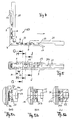
- the guide piece 1 of Figure 1 can be assembled in a simple way a corner drive.
- the parts of such are shown in FIG .
- the forces-transmitting band 30 of three bands 30a, 30b and 30c which are dimensioned differently to a predetermined extent slightly different in length and at their ends have openings 31 and 32 for riveting with coupling pieces 20 and 21 respectively.
- Each coupling piece has a rivet end 20b, 21b and a coupling end 20a or 21a for a connecting rod to be connected. Furthermore, each coupling piece over a part of its length on a guide slot 20bc and 21c.
- FIG. 2 The parts shown in Figure 2 are shown in Figure 3 in section and form a mounted corner drive 50.
- the one leg 3 in the support and guide portion 10b has a centrally disposed opening 14, whose meaning further explained below becomes.
- Figure 4 shows the corner drive in the mounted state in side view.
- the moving parts are in the direction indicated by the arrow end position.
- Figure 5 shows a view - with respect to Figure 4 - from above. It can be seen hidden by the band 30 indicated the arranged in the leg 3 opening 14. Further, it can be seen that the longitudinal slot 21c of the coupling piece 21 abuts in the position shown in Figure 4 with its end on the guide piece 13.
- band packet also: Ribbon package
- the rivet 20b of the Clutch piece 20 riveted to the coupling piece 20 After that the opposite ends of the band 30 from the end of the Leg 2 of the guide angle 1 ago in the support and Guide portion 10a inserted between the guide pieces 6 and on the support and guide portion 10c of the corner region 4th pushed into the area 10b of the angle 3, and so far, that the rivet 21 b of the other coupling piece 21, which with its guide slot 21c threaded over the guide projection 13 into the opening 31 of the tape or tape pack lie down and be engaged with this hole can. This position is shown in FIG. 5a.
- the band 30 is in the guide angle reliably against any bending under Load guided without the band edges of an oversized friction subject.
- the staggered guide pieces 6 and 7 provide for making the guide angle as a casting can and a slight demolding of the casting in the Corner area 4 is ensured.
- the training ensures that the corner drive is relatively smooth and therefore the gearbox only correspondingly lower actuation forces needed.
Landscapes
- Engineering & Computer Science (AREA)
- Mechanical Engineering (AREA)
- Insertion Pins And Rivets (AREA)
- Orthopedics, Nursing, And Contraception (AREA)
Abstract
Description
- Figur 1
- zeigt einen Führungswinkel in perspektivischer Darstellung mit Blick in das Innere des durch die beiden Schenkel gebildeten Winkelbereichs.
- Figur 2
- zeigt ebenfalls in perspektivischer Darstellung die für die Montage einer Eckumlenkung mit dem Führungswinkel nach Figur 1 erforderlichen wenigen Teile in auseinandergezogener Darstellung.
- Figur 3
- zeigt einen zur Ebene des Winkel gelegten Schnitt durch den Führungswinkel mit montierten Teilen der Eckumlenkung.
- Figur 4
- zeigt eine montierte Eckumlenkung mit dem Führungswinkel nach der Erfindung in Seitenansicht.
- Figur 5
- zeigt die Anordnung nach Figur 4 mit Blick in Richtung des einen Schenkels des Führungswinkels und
- Figur 5a, Figur 5b, Figur 5c
- zeigen Querschnitte durch einen Schenkel des Getriebes nach Figur 5 gemäß den in Figur 5 kenntlich gemachten Schnittebenen.
Claims (19)
- Führungswinkel für ein biegbares Band (30) zur über Eck laufenden Übertragung von Kraft oder Schub- und/oder Zug-Bewegungen bei einer Eckumlenkung (50), mit drei Trag- und Führungsbereichen (10a,10b,10c) im Eckbereich (4) und wenigstens auf Teillängen der von dem Eckbereich ausgehenden beiden Schenkel (2,3) des Führungswinkels (1), mit beiderseits aller drei Trag- und Führungsabschnitten verlaufenden Reihen von im Abstand angeordneten Trag- und Führungsstücken (6,7) für das biegbare Band (30), die von den Innenflächen (5,8) der beiden Schenkel und des Eckbereiches aufragen.
- Führungswinkel nach Anspruch 1, bei dem im Eckbereich (4) eine bogenförmig verlaufende Trag- und Führungsfläche (8) vorgesehen ist, entlang der die aufragenden Führungsstücke (7) der sich gegenüberliegenden Reihen gegeneinander auf Lücke oder versetzt angeordnet sind.
- Führungswinkel nach Anspruch 2, dadurch gekennzeichnet, dass der Eckbereich (4) aus Vollmaterial besteht und die entlang seiner bogenförmigen Trag- und Führungsfläche (8) angeordneten Führungsstücke (7) mit Blick in Richtung zur Fläche hakenförmig (7a) ausgebildet sind.
- Führungswinkel nach einem der vorigen Ansprüche, bei dem auf allen drei Trag- und Führungsbereichen (10a,10b,10c) des Führungswinkels (1) die aufragenden Führungsstücke (6,7) der beiden sich gegenüberliegenden Reihen durchgehend auf Lücke oder gegeneinander versetzt angeordnet sind.
- Führungswinkel nach einem der vorigen Ansprüche, bei dem die den Trag- und Führungsbereichen (10a,10b) der beiden Schenkel (2,3) zugeordneten Führungsstücke (6) jeweils im gleichen Abstand von den Schenkelinnenflächen angeordnete, einander zugewandte Führungsschlitze (6a) aufweisen.
- Führungswinkel nach Anspruch 5, dadurch gekennzeichnet, dass im Eckbereich die bogenförmige Trag- und Führungsfläche (8) erhaben so angeordnet ist, dass sie nach beiden Enden hin in der Ebene der Führungsschlitze (6a) ausläuft.
- Führungswinkel nach einem der vorigen Ansprüche, dadurch gekennzeichnet, dass er als einstückiges Gussstück (1) ausgebildet ist.
- Führungswinkel nach Anspruch 7, dadurch gekennzeichnet, dass an wenigstens einem Schenkel (3) außerhalb seines Führungsbereichs (10b) ein aufragender Führungsansatz (13) zum Eingriff in eine Längsnut (21c) eines mit dem Band (30) verbindbaren Kupplungsstücks (21) einstückig mit dem Schenkel (3) ausgeformt ist.
- Führungswinkel nach Anspruch 8, dadurch gekennzeichnet, dass im Trag- und Führungsbereich (10b) des den aufragenden Führungsansatz (13) aufweisenden Schenkels (3)mittig eine Zugangsöffnung (14) für das Vernieten von Bandende und Kupplungsstück vorgesehen ist.
- Führungswinkel nach einem der Ansprüche 8 oder 9, dadurch gekennzeichnet, dass der Führungsansatz (13) eine durchgehende Öffnung (13a) für eine Befestigungsschraube oder dergleichen aufweist.
- Führungswinkel nach einem der Ansprüche 8 bis 10, dadurch gekennzeichnet, dass der andere Schenkel (2) außerhalb seines Trag- und Führungsbereiches (10a) eine mittig angeordnete Öffnung 12) für eine durch die Längsnut (20c) eines Kupplungsstückes (20) greifende Befestigungsschraube oder dergleichen aufweist.
- Führungswinkel nach einem der Ansprüche 7 bis 11, dadurch gekennzeichnet, dass an die freien Enden der beiden Schenkel (2,3) jeweils eine gegenüber der Außenfläche des Schenkels nach außen versetzte Verbindungszunge (16,17) angeformt ist.
- Führungswinkel nach einem der vorigen Ansprüche, dadurch gekennzeichnet, dass die beiden Reihen von aufragenden Führungsstücken (6,7) gegenüber den Schenkelrändern (2a,3a) durchgehend nach innen versetzt angeordnet sind.
- Führungswinkel nach einem der vorigen Ansprüche, dadurch gekennzeichnet, dass der gegenseitige Abstand oder die Lücke (51) zischen zwei Führungsstücken (6,7) mit einer Reihe jeweils im wesentlichen der Länge (52) der Führungsstücke (6), gemessen in Längsrichtung der Trag- und Führungsbereiche (10a,10b,10c), beträgt und die Führungsstücke der gegenüberliegenden Reihe jeweils etwa mittig auf diese Lücke ausgerichtet sind.
- Winkelträger für eine Eckumlenkung, mit zwei Schenkeln (2,3), welche ausgehend von einem gemeinsamen Eckbereich (4) unter einem Winkel von im wesentlichen 90° sich erstrecken, wobei längs von Rändern der beiden Schenkel (2,3) Haltestücke (6) aufragen, welche gegeneinander versetzt sind, zur beidseitigen Führung eines entlang des Winkelträgers eingeschobenen Bandes (30), zur Übertragung von Schub- und Zugkräften längs des Winkelträgers oder der Bandrichtung.
- Winkelträger nach Anspruch 15, wobei die beabstandeten und gegenseitig versetzten Haltestücke (7) auch im Eckbereich (4) vorgesehen sind, in dem die Führungsbahn für das Band (30) gebogen verläuft und an den Enden des bogenförmigen Bereiches stetig in die Erstreckungsrichtung des einen und des anderen Schenkels übergeht.
- Winkelträger nach Anspruch 16, dadurch gekennzeichnet, dass der Eckbereich (4) aus vollmaterial besteht und auf seiner Innenseite eine bogenförmige Führungsfläche für das Band (30) darbietet, der hakenförmige Haltestücke (7) zugeordnet sind.
- Eckumlenkung für Getriebe (50) von Fenstern, Türen oder dergleichen mit einem Führungswinkel (1) nach einem der Ansprüche 1 bis 17, dadurch gekennzeichnet, dass in den Trag- und Führungsbereichen (10a,10b,10c) des Führungswinkels (1) ein Paket (30) aus mehreren, insbesondere aus drei Bändern (30a,30b,30c) von im vorbestimmten Maße abgestufter Länge einschiebbar ist, deren Enden gemeinsam mit Kupplungstücken (20,21) vernietbar sind.
- Verfahren zum Zusammenfügen oder Montieren einer Eckumlenkung mit Führungswinkel nach Anspruch 18, wobeiein Ende eines Bandes oder Bänderpakets (30) mit einem insbesondere langgestreckt ausgebildeten Führungsstück (20) fest vernietet wird;das freie, nicht vernietete Ende des Bands oder Bänderpakets (30) von dem Schenkel (2) des Führungswinkels (1), der keinen aufragenden Führungsansatz (13) aufweist, in die Trag- und Führungsbereiche des Führungswinkels eingeschoben wird, bis ein Nietloch am freien Ende des Bands oder Bänderpakets (30) in einer Fluchtung mit der im Führungsbereich des anderen Schenkels (1) vorgesehenen Vernietungsöffnung (14) gelangt;ein bevorzugt langgestrecktes Kupplungsstück (21) mit dem freien Ende des Bänderpakets von der Vernietungsöffnung (14) aus fest vernietet wird.
Priority Applications (1)
| Application Number | Priority Date | Filing Date | Title |
|---|---|---|---|
| EP20040007691 EP1577478B9 (de) | 2004-03-18 | 2004-03-30 | Eckumlenkung mit Führungsstegstücken zur Bandführung |
Applications Claiming Priority (3)
| Application Number | Priority Date | Filing Date | Title |
|---|---|---|---|
| EP04006563 | 2004-03-18 | ||
| EP04006563 | 2004-03-18 | ||
| EP20040007691 EP1577478B9 (de) | 2004-03-18 | 2004-03-30 | Eckumlenkung mit Führungsstegstücken zur Bandführung |
Publications (3)
| Publication Number | Publication Date |
|---|---|
| EP1577478A1 true EP1577478A1 (de) | 2005-09-21 |
| EP1577478B1 EP1577478B1 (de) | 2013-05-08 |
| EP1577478B9 EP1577478B9 (de) | 2013-07-10 |
Family
ID=34839790
Family Applications (1)
| Application Number | Title | Priority Date | Filing Date |
|---|---|---|---|
| EP20040007691 Expired - Lifetime EP1577478B9 (de) | 2004-03-18 | 2004-03-30 | Eckumlenkung mit Führungsstegstücken zur Bandführung |
Country Status (1)
| Country | Link |
|---|---|
| EP (1) | EP1577478B9 (de) |
Citations (4)
| Publication number | Priority date | Publication date | Assignee | Title |
|---|---|---|---|---|
| CH317810A (de) | 1952-12-09 | 1956-12-15 | Weidtmann Fa Wilhelm | Verschluss für Schwingflügelfenster |
| DE2010407A1 (de) | 1970-03-05 | 1971-09-16 | Siegema Frank KG, 5901 Siegen | Eckumlenkung zum Verbinden der Treib stangen von Fenster und Turbeschlagen |
| DE7418567U (de) | 1974-09-19 | Vereinigte Baubeschlagfabriken Gretsch & Co Gmbh | Umlenkwinkel für Stellgestänge bei Fenstern, Türen oder dergleichen | |
| DE19834038A1 (de) * | 1998-07-29 | 2000-02-10 | Siegenia Frank Kg | Treibstangenbeschlag mit Eckumlenkung |
-
2004
- 2004-03-30 EP EP20040007691 patent/EP1577478B9/de not_active Expired - Lifetime
Patent Citations (4)
| Publication number | Priority date | Publication date | Assignee | Title |
|---|---|---|---|---|
| DE7418567U (de) | 1974-09-19 | Vereinigte Baubeschlagfabriken Gretsch & Co Gmbh | Umlenkwinkel für Stellgestänge bei Fenstern, Türen oder dergleichen | |
| CH317810A (de) | 1952-12-09 | 1956-12-15 | Weidtmann Fa Wilhelm | Verschluss für Schwingflügelfenster |
| DE2010407A1 (de) | 1970-03-05 | 1971-09-16 | Siegema Frank KG, 5901 Siegen | Eckumlenkung zum Verbinden der Treib stangen von Fenster und Turbeschlagen |
| DE19834038A1 (de) * | 1998-07-29 | 2000-02-10 | Siegenia Frank Kg | Treibstangenbeschlag mit Eckumlenkung |
Also Published As
| Publication number | Publication date |
|---|---|
| EP1577478B1 (de) | 2013-05-08 |
| EP1577478B9 (de) | 2013-07-10 |
Similar Documents
| Publication | Publication Date | Title |
|---|---|---|
| DE69630154T2 (de) | Nietenartige Verbindung für überlappende Bandabschnitte | |
| WO1999057457A1 (de) | Energieführungskette | |
| DE3615734C2 (de) | ||
| DE3148331A1 (de) | Linearkugellager | |
| DE69735867T2 (de) | Verbesserte ohrlose Klemme mit flachem Profil | |
| DE3423504A1 (de) | Befestigungsvorrichtung | |
| EP0586671B1 (de) | Energieführungskette | |
| EP0299187B1 (de) | Energieführungskette aus Kunststoff | |
| DE2032517A1 (de) | Rahmengetriebe für Fenster, Türen oder dergleichen | |
| CH628786A5 (de) | Zugelement fuer einen skischuhverschluss. | |
| EP0128391A2 (de) | Bogenförmig verschiebbares Schiebetor | |
| DE19547215A1 (de) | Regal für Kettenglieder einer Energieführungskette | |
| DE102010014054A1 (de) | Öffnungshilfe für Energieführungsketten | |
| DE19600949C2 (de) | Rolladen für Fenster oder Türen | |
| EP1577478B9 (de) | Eckumlenkung mit Führungsstegstücken zur Bandführung | |
| DE19834038C2 (de) | Treibstangenbeschlag mit Eckumlenkung | |
| DE3924468C2 (de) | ||
| CH652565A5 (en) | Element which can be coupled to other similar elements for forming a delimitation of a lawn area from an adjacent open-land area | |
| DE19618912A1 (de) | Lamelle für ein Blatt eines vorzugsweise auf und ab bewegbaren Rollverschlusses für ein Tor, eine Tür, ein Fenster o. dgl. Öffnung | |
| DE29521187U1 (de) | Anschlußglied für eine Energieführungskette | |
| CH664341A5 (de) | Kurvengaengiger plattenbandfoerderer. | |
| DE2939992A1 (de) | Schiebedach fuer fahrzeuge | |
| DE3234519A1 (de) | Lueftungsjalousie | |
| DE10236869A1 (de) | Raffstore mit Wendelager | |
| EP2594704B1 (de) | Riemenanordnung |
Legal Events
| Date | Code | Title | Description |
|---|---|---|---|
| PUAI | Public reference made under article 153(3) epc to a published international application that has entered the european phase |
Free format text: ORIGINAL CODE: 0009012 |
|
| AK | Designated contracting states |
Kind code of ref document: A1 Designated state(s): AT BE BG CH CY CZ DE DK EE ES FI FR GB GR HU IE IT LI LU MC NL PL PT RO SE SI SK TR |
|
| AX | Request for extension of the european patent |
Extension state: AL LT LV MK |
|
| 17P | Request for examination filed |
Effective date: 20060118 |
|
| RAP1 | Party data changed (applicant data changed or rights of an application transferred) |
Owner name: HAUTAU GMBH |
|
| RAP1 | Party data changed (applicant data changed or rights of an application transferred) |
Owner name: HAUTAU GMBH |
|
| AKX | Designation fees paid |
Designated state(s): AT BE BG CH CY CZ DE DK EE ES FI FR GB GR HU IE IT LI LU MC NL PL PT RO SE SI SK TR |
|
| 17Q | First examination report despatched |
Effective date: 20070314 |
|
| GRAP | Despatch of communication of intention to grant a patent |
Free format text: ORIGINAL CODE: EPIDOSNIGR1 |
|
| GRAS | Grant fee paid |
Free format text: ORIGINAL CODE: EPIDOSNIGR3 |
|
| GRAA | (expected) grant |
Free format text: ORIGINAL CODE: 0009210 |
|
| AK | Designated contracting states |
Kind code of ref document: B1 Designated state(s): AT BE BG CH CY CZ DE DK EE ES FI FR GB GR HU IE IT LI LU MC NL PL PT RO SE SI SK TR |
|
| REG | Reference to a national code |
Ref country code: GB Ref legal event code: FG4D Free format text: NOT ENGLISH |
|
| REG | Reference to a national code |
Ref country code: CH Ref legal event code: EP Ref country code: AT Ref legal event code: REF Ref document number: 611197 Country of ref document: AT Kind code of ref document: T Effective date: 20130515 |
|
| REG | Reference to a national code |
Ref country code: IE Ref legal event code: FG4D Free format text: LANGUAGE OF EP DOCUMENT: GERMAN |
|
| REG | Reference to a national code |
Ref country code: DE Ref legal event code: R096 Ref document number: 502004014155 Country of ref document: DE Effective date: 20130711 |
|
| REG | Reference to a national code |
Ref country code: NL Ref legal event code: VDEP Effective date: 20130508 |
|
| PG25 | Lapsed in a contracting state [announced via postgrant information from national office to epo] |
Ref country code: PT Free format text: LAPSE BECAUSE OF FAILURE TO SUBMIT A TRANSLATION OF THE DESCRIPTION OR TO PAY THE FEE WITHIN THE PRESCRIBED TIME-LIMIT Effective date: 20130909 Ref country code: GR Free format text: LAPSE BECAUSE OF FAILURE TO SUBMIT A TRANSLATION OF THE DESCRIPTION OR TO PAY THE FEE WITHIN THE PRESCRIBED TIME-LIMIT Effective date: 20130809 Ref country code: SE Free format text: LAPSE BECAUSE OF FAILURE TO SUBMIT A TRANSLATION OF THE DESCRIPTION OR TO PAY THE FEE WITHIN THE PRESCRIBED TIME-LIMIT Effective date: 20130508 Ref country code: SI Free format text: LAPSE BECAUSE OF FAILURE TO SUBMIT A TRANSLATION OF THE DESCRIPTION OR TO PAY THE FEE WITHIN THE PRESCRIBED TIME-LIMIT Effective date: 20130508 Ref country code: FI Free format text: LAPSE BECAUSE OF FAILURE TO SUBMIT A TRANSLATION OF THE DESCRIPTION OR TO PAY THE FEE WITHIN THE PRESCRIBED TIME-LIMIT Effective date: 20130508 Ref country code: ES Free format text: LAPSE BECAUSE OF FAILURE TO SUBMIT A TRANSLATION OF THE DESCRIPTION OR TO PAY THE FEE WITHIN THE PRESCRIBED TIME-LIMIT Effective date: 20130819 |
|
| PG25 | Lapsed in a contracting state [announced via postgrant information from national office to epo] |
Ref country code: BG Free format text: LAPSE BECAUSE OF FAILURE TO SUBMIT A TRANSLATION OF THE DESCRIPTION OR TO PAY THE FEE WITHIN THE PRESCRIBED TIME-LIMIT Effective date: 20130808 Ref country code: CY Free format text: LAPSE BECAUSE OF FAILURE TO SUBMIT A TRANSLATION OF THE DESCRIPTION OR TO PAY THE FEE WITHIN THE PRESCRIBED TIME-LIMIT Effective date: 20130508 Ref country code: PL Free format text: LAPSE BECAUSE OF FAILURE TO SUBMIT A TRANSLATION OF THE DESCRIPTION OR TO PAY THE FEE WITHIN THE PRESCRIBED TIME-LIMIT Effective date: 20130508 |
|
| PG25 | Lapsed in a contracting state [announced via postgrant information from national office to epo] |
Ref country code: DK Free format text: LAPSE BECAUSE OF FAILURE TO SUBMIT A TRANSLATION OF THE DESCRIPTION OR TO PAY THE FEE WITHIN THE PRESCRIBED TIME-LIMIT Effective date: 20130508 Ref country code: SK Free format text: LAPSE BECAUSE OF FAILURE TO SUBMIT A TRANSLATION OF THE DESCRIPTION OR TO PAY THE FEE WITHIN THE PRESCRIBED TIME-LIMIT Effective date: 20130508 Ref country code: EE Free format text: LAPSE BECAUSE OF FAILURE TO SUBMIT A TRANSLATION OF THE DESCRIPTION OR TO PAY THE FEE WITHIN THE PRESCRIBED TIME-LIMIT Effective date: 20130508 Ref country code: CZ Free format text: LAPSE BECAUSE OF FAILURE TO SUBMIT A TRANSLATION OF THE DESCRIPTION OR TO PAY THE FEE WITHIN THE PRESCRIBED TIME-LIMIT Effective date: 20130508 |
|
| PG25 | Lapsed in a contracting state [announced via postgrant information from national office to epo] |
Ref country code: NL Free format text: LAPSE BECAUSE OF FAILURE TO SUBMIT A TRANSLATION OF THE DESCRIPTION OR TO PAY THE FEE WITHIN THE PRESCRIBED TIME-LIMIT Effective date: 20130508 Ref country code: IT Free format text: LAPSE BECAUSE OF FAILURE TO SUBMIT A TRANSLATION OF THE DESCRIPTION OR TO PAY THE FEE WITHIN THE PRESCRIBED TIME-LIMIT Effective date: 20130508 Ref country code: RO Free format text: LAPSE BECAUSE OF FAILURE TO SUBMIT A TRANSLATION OF THE DESCRIPTION OR TO PAY THE FEE WITHIN THE PRESCRIBED TIME-LIMIT Effective date: 20130508 |
|
| PLBE | No opposition filed within time limit |
Free format text: ORIGINAL CODE: 0009261 |
|
| STAA | Information on the status of an ep patent application or granted ep patent |
Free format text: STATUS: NO OPPOSITION FILED WITHIN TIME LIMIT |
|
| 26N | No opposition filed |
Effective date: 20140211 |
|
| REG | Reference to a national code |
Ref country code: DE Ref legal event code: R097 Ref document number: 502004014155 Country of ref document: DE Effective date: 20140211 |
|
| REG | Reference to a national code |
Ref country code: DE Ref legal event code: R119 Ref document number: 502004014155 Country of ref document: DE |
|
| PG25 | Lapsed in a contracting state [announced via postgrant information from national office to epo] |
Ref country code: LU Free format text: LAPSE BECAUSE OF FAILURE TO SUBMIT A TRANSLATION OF THE DESCRIPTION OR TO PAY THE FEE WITHIN THE PRESCRIBED TIME-LIMIT Effective date: 20140330 |
|
| REG | Reference to a national code |
Ref country code: CH Ref legal event code: PL |
|
| GBPC | Gb: european patent ceased through non-payment of renewal fee |
Effective date: 20140330 |
|
| REG | Reference to a national code |
Ref country code: FR Ref legal event code: ST Effective date: 20141128 |
|
| REG | Reference to a national code |
Ref country code: IE Ref legal event code: MM4A |
|
| REG | Reference to a national code |
Ref country code: DE Ref legal event code: R119 Ref document number: 502004014155 Country of ref document: DE Effective date: 20141001 |
|
| PG25 | Lapsed in a contracting state [announced via postgrant information from national office to epo] |
Ref country code: LI Free format text: LAPSE BECAUSE OF NON-PAYMENT OF DUE FEES Effective date: 20140331 Ref country code: FR Free format text: LAPSE BECAUSE OF NON-PAYMENT OF DUE FEES Effective date: 20140331 Ref country code: IE Free format text: LAPSE BECAUSE OF NON-PAYMENT OF DUE FEES Effective date: 20140330 Ref country code: GB Free format text: LAPSE BECAUSE OF NON-PAYMENT OF DUE FEES Effective date: 20140330 Ref country code: CH Free format text: LAPSE BECAUSE OF NON-PAYMENT OF DUE FEES Effective date: 20140331 Ref country code: DE Free format text: LAPSE BECAUSE OF NON-PAYMENT OF DUE FEES Effective date: 20141001 |
|
| REG | Reference to a national code |
Ref country code: AT Ref legal event code: MM01 Ref document number: 611197 Country of ref document: AT Kind code of ref document: T Effective date: 20140330 |
|
| PG25 | Lapsed in a contracting state [announced via postgrant information from national office to epo] |
Ref country code: AT Free format text: LAPSE BECAUSE OF NON-PAYMENT OF DUE FEES Effective date: 20140330 |
|
| PG25 | Lapsed in a contracting state [announced via postgrant information from national office to epo] |
Ref country code: MC Free format text: LAPSE BECAUSE OF FAILURE TO SUBMIT A TRANSLATION OF THE DESCRIPTION OR TO PAY THE FEE WITHIN THE PRESCRIBED TIME-LIMIT Effective date: 20130508 |
|
| PG25 | Lapsed in a contracting state [announced via postgrant information from national office to epo] |
Ref country code: TR Free format text: LAPSE BECAUSE OF FAILURE TO SUBMIT A TRANSLATION OF THE DESCRIPTION OR TO PAY THE FEE WITHIN THE PRESCRIBED TIME-LIMIT Effective date: 20130508 Ref country code: HU Free format text: LAPSE BECAUSE OF FAILURE TO SUBMIT A TRANSLATION OF THE DESCRIPTION OR TO PAY THE FEE WITHIN THE PRESCRIBED TIME-LIMIT; INVALID AB INITIO Effective date: 20040330 |
|
| PG25 | Lapsed in a contracting state [announced via postgrant information from national office to epo] |
Ref country code: BE Free format text: LAPSE BECAUSE OF NON-PAYMENT OF DUE FEES Effective date: 20140331 |