EP1577477A2 - Ecklager für einen Dreh-Kipp-Beschlag - Google Patents
Ecklager für einen Dreh-Kipp-Beschlag Download PDFInfo
- Publication number
- EP1577477A2 EP1577477A2 EP05101379A EP05101379A EP1577477A2 EP 1577477 A2 EP1577477 A2 EP 1577477A2 EP 05101379 A EP05101379 A EP 05101379A EP 05101379 A EP05101379 A EP 05101379A EP 1577477 A2 EP1577477 A2 EP 1577477A2
- Authority
- EP
- European Patent Office
- Prior art keywords
- bearing
- corner
- base plate
- sleeve
- tabs
- Prior art date
- Legal status (The legal status is an assumption and is not a legal conclusion. Google has not performed a legal analysis and makes no representation as to the accuracy of the status listed.)
- Withdrawn
Links
- 238000009423 ventilation Methods 0.000 description 6
- 239000002184 metal Substances 0.000 description 2
- 238000009434 installation Methods 0.000 description 1
- 230000036316 preload Effects 0.000 description 1
Images
Classifications
-
- E—FIXED CONSTRUCTIONS
- E05—LOCKS; KEYS; WINDOW OR DOOR FITTINGS; SAFES
- E05D—HINGES OR SUSPENSION DEVICES FOR DOORS, WINDOWS OR WINGS
- E05D15/00—Suspension arrangements for wings
- E05D15/48—Suspension arrangements for wings allowing alternative movements
- E05D15/52—Suspension arrangements for wings allowing alternative movements for opening about a vertical as well as a horizontal axis
- E05D15/5214—Corner supports
-
- E—FIXED CONSTRUCTIONS
- E05—LOCKS; KEYS; WINDOW OR DOOR FITTINGS; SAFES
- E05D—HINGES OR SUSPENSION DEVICES FOR DOORS, WINDOWS OR WINGS
- E05D15/00—Suspension arrangements for wings
-
- E—FIXED CONSTRUCTIONS
- E05—LOCKS; KEYS; WINDOW OR DOOR FITTINGS; SAFES
- E05D—HINGES OR SUSPENSION DEVICES FOR DOORS, WINDOWS OR WINGS
- E05D3/00—Hinges with pins
- E05D3/02—Hinges with pins with one pin
- E05D3/022—Hinges with pins with one pin allowing an additional lateral movement, e.g. for sealing
-
- E—FIXED CONSTRUCTIONS
- E05—LOCKS; KEYS; WINDOW OR DOOR FITTINGS; SAFES
- E05Y—INDEXING SCHEME ASSOCIATED WITH SUBCLASSES E05D AND E05F, RELATING TO CONSTRUCTION ELEMENTS, ELECTRIC CONTROL, POWER SUPPLY, POWER SIGNAL OR TRANSMISSION, USER INTERFACES, MOUNTING OR COUPLING, DETAILS, ACCESSORIES, AUXILIARY OPERATIONS NOT OTHERWISE PROVIDED FOR, APPLICATION THEREOF
- E05Y2600/00—Mounting or coupling arrangements for elements provided for in this subclass
- E05Y2600/60—Mounting or coupling members; Accessories therefor
- E05Y2600/622—Dowels; Pins
-
- E—FIXED CONSTRUCTIONS
- E05—LOCKS; KEYS; WINDOW OR DOOR FITTINGS; SAFES
- E05Y—INDEXING SCHEME ASSOCIATED WITH SUBCLASSES E05D AND E05F, RELATING TO CONSTRUCTION ELEMENTS, ELECTRIC CONTROL, POWER SUPPLY, POWER SIGNAL OR TRANSMISSION, USER INTERFACES, MOUNTING OR COUPLING, DETAILS, ACCESSORIES, AUXILIARY OPERATIONS NOT OTHERWISE PROVIDED FOR, APPLICATION THEREOF
- E05Y2900/00—Application of doors, windows, wings or fittings thereof
- E05Y2900/10—Application of doors, windows, wings or fittings thereof for buildings or parts thereof
- E05Y2900/13—Type of wing
- E05Y2900/148—Windows
Definitions
- the invention relates to a corner bearing for a turn-tilt fitting a window, a French window or the like, with an intended in a closed position of the Fittings vertical bearing pin of a rotary bearing of the Fittings and having a horizontal bearing axis Tipping storage of the fitting and with a bracket the tilting bearing for supporting the bearing pin.
- Such corner bearings serve to support a wing opposite a frame of a fitting equipped Window.
- the wing In the rotational position, the wing can be turn around the bearing pin.
- the bearing pin remains here in its vertical position. In tilted position is the wing around the horizontal bearing axis of the tilting bearing tilted.
- a corner bearing for a turn-tilt wing of a window is known for example from DE 93 08 673 U. in this connection the bearing pin is made in one piece with the bracket.
- a base plate of the corner bearing has the holding block embracing tabs on. The bearing axis of the tilting bearing penetrates the tabs and the bracket and allows thus pivoting the bearing pin to the Bearing axle of the tilting bearing.
- the base plate forms with it a crosspiece for holding the tabs.
- a disadvantage of the known corner bearing is that the bearing axis the tilt bearing of the tabs of the base plate is spaced apart from the frame to a predetermined extent. This leads to a very large distance.
- the invention is based on the problem of a corner bearing of the aforementioned type so that the bearing axis in the mounted on the window state of the Corner bearing can be arranged particularly close to the frame.
- An additional spacing of the Bearing axle of the frame through the crossbar is thanks avoided the invention.
- the tabs and so that the cross bar made of a very strong sheet metal be without the distance of the bearing axis increases.
- the bearing axis can therefore be particularly close to the frame to be ordered.
- a support plate supporting the base plate can have a recess in the region of the tabs. This contributes to further reducing the distance of the Bearing axis of the frame in the assembled state of the invention Corner warehouse at.
- a night ventilation position of the fitting requires according to another advantageous embodiment of the invention a particularly low structural complexity, if one too the bearing pin of the pivot bearing and the bearing axis of the Kipplagerung angled longitudinal guide one with a Base plate has connected sleeve and if the hanger bracket is connected to a guided in the sleeve bolt. By connecting the bracket with the bolt leaves arrange the bearing axis particularly close to the frame.
- a movement of the longitudinal guide during the adjustment of the Fittings in a tilted position can be according to another advantageous development of the invention simple Avoid when the tabs facing at their base plate Page a radius with the origin in the bearing axis have and support themselves on the base plate. The radius allows immediate sliding along the tabs on the base plate. Another advantage This design is that friction losses the corner bearing in the operation of the fitting especially be kept low.
- a grid for holding the bearing pin in the vertical Location requires according to another advantageous
- a reliable closing of the invention Corner bearing equipped fitting is easy to ensure if the longitudinal guide a spring element for Preload the bolt in the deepest in the sleeve has located position.
- the corner bearing according to the invention leaves on the window Simply determine whether the receiving bore sufficient is deep when the sleeve of the longitudinal guide shorter is as the bolt guided in the sleeve when a stop connected to the sleeve and when the stop with a concern of the tabs on the base plate up to guided the free end of the bolt.
- the short length the sleeve has the advantage that the longitudinal guide easy to assemble and that possible dirt from the Longitudinal guide can be easily removed.
- An end stop of the longitudinal guide and a possible support of the spring element requires according to another advantageous development of the invention a particularly low constructional effort, if the guided in the sleeve Bolt at its free end a radial broadening having.
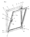
- Figure 1 shows a window with a mounted on a frame 1 Wing 2 and with a drive rod fitting 3.
- the wing 2 is in a tilted position about a tilt axis 4 shown tilted and is a Ausstellschere. 5 held.
- the wing 2 can be moved against the frame 1 and put in a closed position in which he is in the frame 1 is locked. Furthermore, can the Turn wing 2 about a rotation axis 6.
- the window has a corner bearing 7.
- the Ausstellschere 5 is held on a pivot bearing 8 while on the tilting axis 4, away from the corner bearing 7, a tilting bearing 9 is arranged.
- the settlements of the wing 2 compensates.
- the espagnolette fitting 3 has a groove in the Wing 2 arranged, longitudinally displaceable drive rod on. On the drive rod are a plurality of locking pins 10th arranged. The locking pins 10 are fixed to the frame Striking plates 11 opposite. One of the strike plates 11 ' is arranged on a scissor arm 12 of the Ausstellschere 5.
- the drive rod of the espagnolette fitting 3 can be from a handle 13 and drive the locking pin 10, 10 'move. Located in the position shown the handle 13 in the tilted position marked K. If you move the handle 13 in the marked D Position, is the espagnolette fitting 3 in a rotational position in which the wing of the second to rotate about the vertical axis 6. In the with Z, L marked position of the handle 13 is located the wing 2 optionally in the closed position Z, in the he is locked to the frame 1 or in a night ventilation position L, in which he is a crack far from the Frame 1 is removed. Furthermore, the espagnolette has on the tilting bearing 9 and the corner bearing 7 arranged Striker plates 14, 14 '.
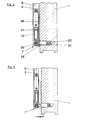
- Figure 2 shows enlarged in a sectional view along the line II - II the window of Figure 1 in the area of the corner bearing 7.
- the corner bearing 7 has a in the Rotary axis 6 lying vertical bearing pin 15 a Wheellagerung and one perpendicular to the plane arranged Bearing axle 16 a tilting bearing.
- On the wing 2 a bearing member 17 is fixed, which the bearing pin 15 takes up.
- the frame 1 is a base plate 18th screwed, which is connected to a sleeve 19.
- the frame 1 has a bore 20th on.
- the sleeve 19 has a in the bore 20th the frame projecting stop 21st
- FIG. 3 shows the window from FIG. 2 in a night ventilation position, in the wing 2 in its plane of the frame 1 is spaced by a gap a.
- These Night ventilation position can be achieved when the wing 2 by hand or by means of the drive in FIG. 1 illustrated espagnolette fitting 3 in its plane is removed from the frame 1.
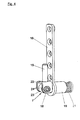
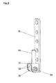
- Figure 4 shows greatly enlarged the corner bearing 7 in one perspective view. It can be seen here that the bearing pin 15 is arranged on a transverse web 22 is. The bearing pin 15 is connected via a holding block 23 with the bearing axis 16 of the tilting storage connected. The hanger 23 is connected to the bearing axis 16 tabs 24 laterally enclosed. The holding block 23, the bearing axis 16 and connected via the crosspiece 22 tabs 24 thus form the tilting bearing of the corner bearing. 7 for the window shown in FIG.
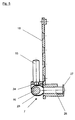
- FIG. 5 shows a sectional view through the corner bearing 7 of Figure 4, that the holding block 23 integral with a bolt 25 a longitudinal guide 26 is made.
- the longitudinal guide 26 allows the removal of the support bracket 23 of the Base plate 18 by the dimension a mentioned in FIG. 3 and thus the placement of the wing 2 in the night ventilation position.
- the bolt 25 has a radial Broadening 27.
- the tabs 24 have a radius r with an origin corresponding to the bearing axis 16.
- Fig. 5 is also seen that the corner bearing without a spring element can be executed, since the shut-off and also suit movement of the sash against the Frame through the elements of the espagnolette fitting takes place and the corner bearing only the required Degree of freedom provides.
- FIG. 6 shows a further embodiment of the corner bearing 7, which for a turn-tilt fitting without night vent position is provided.
- a hanger 30 directly attached to the base plate 18.
- the crossbar 31 is connected to the bearing pin 15 of the pivot bearing connected.
Landscapes
- Engineering & Computer Science (AREA)
- Mechanical Engineering (AREA)
- Wing Frames And Configurations (AREA)
- Pivots And Pivotal Connections (AREA)
Applications Claiming Priority (2)
| Application Number | Priority Date | Filing Date | Title |
|---|---|---|---|
| DE102004013299 | 2004-03-18 | ||
| DE200410013299 DE102004013299A1 (de) | 2004-03-18 | 2004-03-18 | Ecklager für einen Dreh-Kipp-Beschlag |
Publications (2)
| Publication Number | Publication Date |
|---|---|
| EP1577477A2 true EP1577477A2 (de) | 2005-09-21 |
| EP1577477A3 EP1577477A3 (de) | 2009-12-16 |
Family
ID=34833172
Family Applications (1)
| Application Number | Title | Priority Date | Filing Date |
|---|---|---|---|
| EP05101379A Withdrawn EP1577477A3 (de) | 2004-03-18 | 2005-02-23 | Ecklager für einen Dreh-Kipp-Beschlag |
Country Status (2)
| Country | Link |
|---|---|
| EP (1) | EP1577477A3 (zh) |
| DE (1) | DE102004013299A1 (zh) |
Cited By (2)
| Publication number | Priority date | Publication date | Assignee | Title |
|---|---|---|---|---|
| CN101910536A (zh) * | 2008-01-15 | 2010-12-08 | 诺托·弗朗克股份有限公司 | 用于窗户、门及类似物件的角支承 |
| CN111075314A (zh) * | 2019-11-30 | 2020-04-28 | 上海恒江幕墙装饰工程有限公司 | 一种多向旋转的便捷式铝合金窗户 |
Families Citing this family (1)
| Publication number | Priority date | Publication date | Assignee | Title |
|---|---|---|---|---|
| DE102018207083A1 (de) * | 2018-05-07 | 2019-11-07 | Roto Frank Ag | Gebäudeverschlusseinrichtung |
Citations (4)
| Publication number | Priority date | Publication date | Assignee | Title |
|---|---|---|---|---|
| DE7038636U (de) | 1970-10-20 | 1971-01-14 | Siegenia Frank Kg | Ecklager fuer fenster und tueren od.dgl.mit kipp-schwenkfluegel |
| DE7818899U1 (de) * | 1978-06-23 | 1978-10-05 | Siegenia-Frank Kg, 5900 Siegen | Ecklager fuer dreh-kippfluegel von fenstern, tueren o.dgl. |
| DE9308673U1 (de) | 1993-06-10 | 1994-10-27 | Gretsch Unitas Gmbh | Ecklagerbock für einen Dreh-Kipp-Flügel eines Fensters, einer Tür o.dgl. |
| US20030217821A1 (en) | 2002-05-14 | 2003-11-27 | Pacholke Glen Douglas | Floating pivot mount for a folding panel |
Family Cites Families (4)
| Publication number | Priority date | Publication date | Assignee | Title |
|---|---|---|---|---|
| DE1744322U (de) * | 1957-03-01 | 1957-05-02 | Friedrich Hahn G M B H | Eckfitsche fuer dreh-kippfenster. |
| AT226111B (de) * | 1961-11-29 | 1963-02-25 | Lapp Finze Ag | Traglager für einen Drehkippbeschlag von Fenstern, Türen u. dgl. |
| DE2057727A1 (de) * | 1970-11-24 | 1972-05-31 | Siegenia Frank Kg | Ecklager fuer Fenster und Tueren od.dgl. mit Kipp-Schwenkfluegeln |
| DE7631279U1 (de) * | 1976-10-06 | 1977-02-03 | Schaumburg-Lippische Baubeschlagfabrik W. Hautau Gmbh Kirchhorsten, 3061 Helpsen | Einjustierbares unteres ecklager fuer dreh/kippfluegel von fenstern, tueren oder dergleichen |
-
2004
- 2004-03-18 DE DE200410013299 patent/DE102004013299A1/de not_active Withdrawn
-
2005
- 2005-02-23 EP EP05101379A patent/EP1577477A3/de not_active Withdrawn
Patent Citations (4)
| Publication number | Priority date | Publication date | Assignee | Title |
|---|---|---|---|---|
| DE7038636U (de) | 1970-10-20 | 1971-01-14 | Siegenia Frank Kg | Ecklager fuer fenster und tueren od.dgl.mit kipp-schwenkfluegel |
| DE7818899U1 (de) * | 1978-06-23 | 1978-10-05 | Siegenia-Frank Kg, 5900 Siegen | Ecklager fuer dreh-kippfluegel von fenstern, tueren o.dgl. |
| DE9308673U1 (de) | 1993-06-10 | 1994-10-27 | Gretsch Unitas Gmbh | Ecklagerbock für einen Dreh-Kipp-Flügel eines Fensters, einer Tür o.dgl. |
| US20030217821A1 (en) | 2002-05-14 | 2003-11-27 | Pacholke Glen Douglas | Floating pivot mount for a folding panel |
Cited By (3)
| Publication number | Priority date | Publication date | Assignee | Title |
|---|---|---|---|---|
| CN101910536A (zh) * | 2008-01-15 | 2010-12-08 | 诺托·弗朗克股份有限公司 | 用于窗户、门及类似物件的角支承 |
| CN101910536B (zh) * | 2008-01-15 | 2013-10-02 | 诺托·弗朗克股份有限公司 | 用于窗户、门及类似物件的角支承 |
| CN111075314A (zh) * | 2019-11-30 | 2020-04-28 | 上海恒江幕墙装饰工程有限公司 | 一种多向旋转的便捷式铝合金窗户 |
Also Published As
| Publication number | Publication date |
|---|---|
| DE102004013299A1 (de) | 2005-09-29 |
| EP1577477A3 (de) | 2009-12-16 |
Similar Documents
| Publication | Publication Date | Title |
|---|---|---|
| DE202008004933U1 (de) | Beschlag für einen zumindest kippbaren und/oder parallelabstellbaren Flügel eines Fensters, einer Tür o.dgl. | |
| DE202014102405U1 (de) | Verriegelungsvorrichtung für Schwenkschiebetüren von Fahrzeugen des öffentlichen Personenverkehrs; Schwenkschiebetür mit Verriegelungsvorrichtung | |
| EP0515931B2 (de) | Drehkippbeschlag | |
| DE2648344B2 (de) | Beschlag für Schiebefenster, Schiebetüren o.dgl. | |
| EP3102759A1 (de) | Beschlag eines zumindest hebbaren, vorzugsweise aber auch verschiebbaren flügels von fenstern oder türen | |
| DE8308201U1 (de) | Zumindest an seinem unteren ende ausstellbarer fluegel eines fensters, einer tuer od. dgl. | |
| DE202008004292U1 (de) | Beschlag für eine Ausstell- und Kippbewegung eines Flügels eines Gebäudefensters oder einer Gebäudetür | |
| DE102021101448B4 (de) | Automatikschiebetür mit Schließeinrichtung und Verfahren zum Verriegeln | |
| EP1577477A2 (de) | Ecklager für einen Dreh-Kipp-Beschlag | |
| DE102007030086A1 (de) | Sensorvorrichtung für einen Antrieb einer Tür oder eines Fensters | |
| EP3752700A1 (de) | Absenkbare einbruchsicherung | |
| EP2142736B1 (de) | Beschlag für ein fenster, eine tür oder dergleichen | |
| DE202021105180U1 (de) | Fenster | |
| DE202021102238U1 (de) | Drehkippfenster und Beschlaganordnung | |
| DE3202879C2 (de) | Beschlagsanordnung für Schiebetüren (Panik-Beschlag) | |
| AT509464B1 (de) | Schloss | |
| EP1764461A2 (de) | Verriegelungsvorrichtung für Schiebetüren | |
| DE102015225655B4 (de) | Fensterbrett und damit ausgestattetes Fenster | |
| EP1757765B1 (de) | Feingerahmte Tür | |
| EP4174268B1 (de) | Schiebetürrollenbeschlag und zugehörige schiebetürenanordnung | |
| EP2369111B1 (de) | Zur verdeckten Anordnung vorgesehenes Ecklager | |
| EP2392756B1 (de) | Zur verdeckten Anordnung vorgesehenes Ecklager | |
| EP3382130B1 (de) | Verriegelungseinheit und fenster oder türe mit einer solchen verriegelungseinheit | |
| DE202006019139U1 (de) | Beschlaggarnitur für Paniktürverschlüsse | |
| DE2020240A1 (de) | Verschluss fuer einen Schwenk-Kippfluegel eines Fensters,einer Tuer od.dgl. |
Legal Events
| Date | Code | Title | Description |
|---|---|---|---|
| PUAI | Public reference made under article 153(3) epc to a published international application that has entered the european phase |
Free format text: ORIGINAL CODE: 0009012 |
|
| AK | Designated contracting states |
Kind code of ref document: A2 Designated state(s): AT BE BG CH CY CZ DE DK EE ES FI FR GB GR HU IE IS IT LI LT LU MC NL PL PT RO SE SI SK TR |
|
| AX | Request for extension of the european patent |
Extension state: AL BA HR LV MK YU |
|
| PUAL | Search report despatched |
Free format text: ORIGINAL CODE: 0009013 |
|
| AK | Designated contracting states |
Kind code of ref document: A3 Designated state(s): AT BE BG CH CY CZ DE DK EE ES FI FR GB GR HU IE IS IT LI LT LU MC NL PL PT RO SE SI SK TR |
|
| AX | Request for extension of the european patent |
Extension state: AL BA HR LV MK YU |
|
| 17P | Request for examination filed |
Effective date: 20100510 |
|
| AKX | Designation fees paid |
Designated state(s): AT BE BG CH CY CZ DE DK EE ES FI FR GB GR HU IE IS IT LI LT LU MC NL PL PT RO SE SI SK TR |
|
| 17Q | First examination report despatched |
Effective date: 20110628 |
|
| STAA | Information on the status of an ep patent application or granted ep patent |
Free format text: STATUS: THE APPLICATION IS DEEMED TO BE WITHDRAWN |
|
| 18D | Application deemed to be withdrawn |
Effective date: 20120901 |