EP1577472B1 - Gleiterbauteil und Feststell- oder Austellvorrichtung für den Beschlag von Fensternflügeln - Google Patents
Gleiterbauteil und Feststell- oder Austellvorrichtung für den Beschlag von Fensternflügeln Download PDFInfo
- Publication number
- EP1577472B1 EP1577472B1 EP05102079A EP05102079A EP1577472B1 EP 1577472 B1 EP1577472 B1 EP 1577472B1 EP 05102079 A EP05102079 A EP 05102079A EP 05102079 A EP05102079 A EP 05102079A EP 1577472 B1 EP1577472 B1 EP 1577472B1
- Authority
- EP
- European Patent Office
- Prior art keywords
- locking device
- slide component
- notches
- section
- guide rail
- Prior art date
- Legal status (The legal status is an assumption and is not a legal conclusion. Google has not performed a legal analysis and makes no representation as to the accuracy of the status listed.)
- Expired - Lifetime
Links
Images

Classifications
-
- E—FIXED CONSTRUCTIONS
- E05—LOCKS; KEYS; WINDOW OR DOOR FITTINGS; SAFES
- E05C—BOLTS OR FASTENING DEVICES FOR WINGS, SPECIALLY FOR DOORS OR WINDOWS
- E05C17/00—Devices for holding wings open; Devices for limiting opening of wings or for holding wings open by a movable member extending between frame and wing; Braking devices, stops or buffers, combined therewith
- E05C17/02—Devices for holding wings open; Devices for limiting opening of wings or for holding wings open by a movable member extending between frame and wing; Braking devices, stops or buffers, combined therewith by mechanical means
- E05C17/04—Devices for holding wings open; Devices for limiting opening of wings or for holding wings open by a movable member extending between frame and wing; Braking devices, stops or buffers, combined therewith by mechanical means with a movable bar or equivalent member extending between frame and wing
- E05C17/12—Devices for holding wings open; Devices for limiting opening of wings or for holding wings open by a movable member extending between frame and wing; Braking devices, stops or buffers, combined therewith by mechanical means with a movable bar or equivalent member extending between frame and wing consisting of a single rod
- E05C17/24—Devices for holding wings open; Devices for limiting opening of wings or for holding wings open by a movable member extending between frame and wing; Braking devices, stops or buffers, combined therewith by mechanical means with a movable bar or equivalent member extending between frame and wing consisting of a single rod pivoted at one end, and with the other end running along a guide member
- E05C17/28—Devices for holding wings open; Devices for limiting opening of wings or for holding wings open by a movable member extending between frame and wing; Braking devices, stops or buffers, combined therewith by mechanical means with a movable bar or equivalent member extending between frame and wing consisting of a single rod pivoted at one end, and with the other end running along a guide member with braking, clamping or securing means at the connection to the guide member
-
- E—FIXED CONSTRUCTIONS
- E05—LOCKS; KEYS; WINDOW OR DOOR FITTINGS; SAFES
- E05B—LOCKS; ACCESSORIES THEREFOR; HANDCUFFS
- E05B15/00—Other details of locks; Parts for engagement by bolts of fastening devices
- E05B15/16—Use of special materials for parts of locks
- E05B15/1635—Use of special materials for parts of locks of plastics materials
Definitions
- the invention relates to a locking or Ausstellvortechnisch according to the introductory words of claim 1, in particular also a Gleiterbauteil for use in fitting technology.
- the locking device achieved in the installed state to set a (desired) opening angle of a wing of windows or doors. This is done with a, by a handle in at least two positions movable, concealed in a fitting groove of the casement arranged actuating linkage (in the installed state).
- the slider component has a fuselage section slidable in a guide rail, which can be attached between a rod section and two edge flanges of the guide rail and can be coupled to one end of a link. The other end of the link is hinged at a distance from a - defined by hinges of the wing - wing axis to a frame (rotatably arranged).
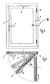
- the invention is concerned with the focus with an element of a complex device, which is not shown separately and extensively, only a schematic representation of such a locking or Ausstell adopted with a scissor arm and a C-shaped rail is in the FIGS. 1 . 5 and 6 shown. This is referred to insofar.
- the slider as a "slider member” is received in the preferred C-shaped rail as a guide rail and has certain properties due to its shapes.
- a bottom of the guide rail has in its longitudinal direction after a predetermined pitch arranged longitudinal window (graduation measure), which are spaced from each other by floor webs.
- the rod section has over the same pitch distributed over its length top depressions (depressions) whose lower side formations depending on the relative position of rod section relative to the ground engage in the bottom window or sit on the bottom webs.
- a clear height between the bottom webs and the underside of the edge flanges of the guide rail and a total height of the rod portion in the region of the formations and the height of shoulder surfaces on the body portion of the Gleiterbauteils are matched: When sliding the moldings on the floor webs sits the Gleiterbauteil with its shoulder surfaces on the Edge flanges of the guide rail firmly. An improved braking or detection results in this way.
- the slider component is elongated and consists of a large base section, in which two notches are inserted from above.
- the notches have an axially constant distance.
- a bridge forms, which extends in the height direction. This web is used to be used between two inner edges or such edges of the guide rail and guided, preferably in C-shaped rail.
- Mechanical braking forces are additionally and preferably applied in the notches, by engaging wedge-shaped protruding, in particular down, directed to the bottom of the base portion web portions of the C-shaped rail (claim 21) when the slider is pushed by the push rod upwards.
- the sliding member has a greater length than width and height. It is "elongated” trained. The width is narrow, compared to the long one.
- the notch shape does not necessarily have to be pointed at the bottom (claim 12), but a V-shaped notch shape is preferred in which a slight rounding occurs at the bottom and two walls are formed between which a respective web section engages from above from the C-rail ,
- the notches extend longitudinally (claim 3 or 14) but are together narrower than the width of the slider member.
- the V-shaped aligned walls are formed so that a wall is oriented substantially perpendicular and a more inclined relative to the vertical (claim 22).
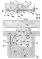
- FIG. 1 illustrates a non-braking position of the slider G, wherein a rising edge of a suppression 11 a immediately before a web 17 a, for further movement into the braking position after FIG. 1a ,
- the function of the slider is in the position of FIG. 1 , illustrated in the sectional view of FIG. 2 especially clear. It has a preferably made of plastic, as a plastically deformable material, formed body portion 40, in which - seen in section - two longitudinal notches 41,42 are introduced, which are provided with the inner distance b1. Each of these notches has a substantially vertically oriented wall 41.2 or 42.2 and a more inclined wall 41.1 or 42.1.
- the two vertical walls 41.2 and 42.2 delimit a web 40a, which rises and preferably protrudes from the top of the profile 15 through a through opening 15e (as a gap).
- the web 40a may centrally have a further opening 50 through which a pin 60 is inserted, to which a scissor arm 70 is rotatably articulated, wherein the pin 60 is formed on the upper side in the section 61 tapers.
- two horizontal web portions and two vertically, wedge-shaped and downwardly directed web portions 15a, 15a 'and 15b, 15b' are provided at the top.
- the latter vertically aligned portions engage in the notches 41,42 and guide the slider in its longitudinal movement.
- a rail portion 11 is placed below the slider G touching on its underside 40b and can exert forces on the slider by means of recesses and depressions controlled via its upper side, as shown in the following figures.
- the distance of the vertical walls 41.2 and 42.2 corresponds to b1, which distance is smaller than the total width b of the slider, which in turn is slightly narrower in its overall width than the space within the acting as a housing C-profile 15 with its side walls 15c, 15d.
- the length I of the slider is substantially greater than the width b, in particular more than four times as large.
- the height is determined by the upstanding web portion 40a, which is slightly smaller than the width and substantially lower than the length I. In the specific example, the height is only between 15% to 20% of the length.
- a substantially parallelepiped attachment 40a ' can be mounted substantially centrally, which is provided in the region of the bore 50 and is larger in area than this.
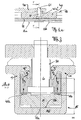
- the rail 11 lifts the slider G with its body 40, wherein the inclined wall 41.1 and 42.1 of the respective notch is applied directly to the projecting wedge-shaped web portion 15a 'and 15b' and the associated gap is reduced to zero.
- a gap is in the non-adjacent state in FIG. 4 illustrated, and with reference numerals S.1 and S.2 for the respective notch illustrated. In FIG. 2 this gap has become zero, in the braking position with the forces acting F 1 , F 2 , F 1 'and F 2 '.
- the surfaces 42.1 and 41.1 transmit normal forces to the center.
- F 0 of the slider By lifting F 0 of the slider, the force is increased and thus also the frictional forces or braking forces at the point of contact of the two surfaces or the respective surface pair of the respective notch.
- a saddle can be placed over the center bar and protrude into both columns, to convey the braking and holding forces.
- the walls of a respective notch ie the walls 41.1 and 41.2 on the one hand or the walls 42.1 and 42.2 have an angle between 20 ° and 40 °, essentially occupied by 30 °, between them.
- the downwardly projecting web 15a 'and 15b' is formed at such an angle.
- the C-profile 15 is pressed in the upper region to the center (on the vertical flanks 15c, 15d, which are used as a bending distance m) to the vertical surface portions 41.2 and 42.2 for abutment with the vertical wall portions of the downwardly projecting webs to be pressed, which limits the deformation of the C-rail. Due to the frictional engagement, the braking effect is present and the slider can absorb displacement forces in the longitudinal direction (and block movement).
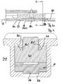
- the rail 11 is provided with a number of elevations (recesses) 11 a, 11 ab and 11 b transverse to the longitudinal axis, which have a pitch.
- the pitch corresponds to the adjustment, wherein the pitch corresponds to openings 16a, 16b in the bottom 15f of the C-profile 15.
- the pitch T is dimensioned (graduation size) so that the standard thrusts of transmissions can be used and inaccuracies in the assembly can be compensated.
- the length of a breakthrough 16a simultaneously compensates for different transmission strokes, reference being made to the application which the FIGS.
- the adjustment can be defined at 180 ° rotary handle or at 90 ° rotary handle (actuation).
- the division of the rail 15 may correspond to the adjustment.
- a function of detection is described as follows.
- the rail 11 shifts. With a thickening or molding 11a, 11b, corresponding to the pitch T, it moves in its longitudinal movement against residual webs 17a, 17b, between the recesses 16a, 16b.
- the rail is raised and pushes the sliding member G with its body 40 upwards in the direction of the opening 15e of the C-profile.
- a plastic deformation of the slider which is preferably made of plastic, forms a tension, the C-profile is stretched and reaches a clamping action.
- the length I of the slider G or its trunk 40 is significantly longer than a respective recess, which results in a molding 11 a or 11 b in the rail 11. Thus, clamping is possible in any position without the slider being received in its entirety by one of these indentations (seen from the top).
- the release of the fixed position is achieved by turning back the handle 4.
- the rail elevations 11a, 11b neither drive into the recesses 16a, 16b of the C-shaped rail 15 to rotatably control the wing F with its frame 2 again.
- the intermediate portion 11ab, located between the protrusions 11a, 11b, comes to lie on the web 17 and determines a non-braking position (release position).
- a slider component for a locking device made of plastic or a plastically deformable other material, with a greater length (I) than width (b), and for use in the fitting area in a locking device or a display device (6), in particular with displacement state, transition position from sliding position to braking position and at least one braking position.
- the slider has a base portion (40) and two longitudinally extending notches (41, 42) spaced from each other by a distance (b1).
- the distance (b1) is occupied by a web portion (40a) which extends over a multiple of its width (b1) in the axial direction.
Landscapes
- Engineering & Computer Science (AREA)
- Mechanical Engineering (AREA)
- Window Of Vehicle (AREA)
- Bearings For Parts Moving Linearly (AREA)
- Wing Frames And Configurations (AREA)
- Specific Sealing Or Ventilating Devices For Doors And Windows (AREA)
- Special Wing (AREA)
Description
- Die Erfindung betrifft eine Feststell- oder Ausstellvorrichtung nach den einleitenden Worten des Anspruchs 1, insbesondere auch ein Gleiterbauteil zum Einsatz in der Beschlagstechnik. Die Feststellvorrichtung erreicht im eingebauten Zustand einen (gewünschten) Öffnungswinkel eines Flügels von Fenstern oder Türen einzustellen. Dies erfolgt mit einem, durch einen Handgriff in wenigstens zwei Stellungen bewegbares, in einer Beschlagsnut des Flügelrahmens verdeckt angeordneten Betätigungsgestänge (im eingebauten Zustand). Das Gleiterbauteil hat einen in einer Führungsschiene gleitend verschiebbaren Rumpfabschnitt, der zwischen einem Stangenabschnitt und zwei Randflanschen der Führungsschiene anbringbar ist und mit dem einen Ende eines Lenkers gekoppelt werden kann. Das andere Ende des Lenkers wird im Abstand von einer - durch Scharniere des Flügels definierten - Flügelachse an einem Blendrahmen angelenkt (drehbar angeordnet).
- Aus der
DE-C 195 16 588 (Weidtmann ) ist eine Feststellvorrichtung für Flügel dem Fachmann zugänglich, welche einen Gleiterbauteil besitzt, der dort mit 50 benannt ist, vgl.Figuren 3 und5 ,6 der dortigen Offenbarung. Mit einer Treibschiene wird eine Zwischenschiene aufwärts und abwärts bewegt, die mit einer Federkraft vorgespannt ist und eine Verzahnung aufweist, die in eine Gegenzahnung am Gleiterbauteil eingreift, um das Gleiterbauteil in seiner Position zu verriegeln. Bewegt sich die Treibschiene weiter und löst sie den Kontakt der aufwärts gerichteten Verformung gegen abwärts orientierte Vorsprünge, so kann die Federvorspannung die Zwischenschiene wieder abwärts drücken und den Verzahnungseingriff lösen. Die vorhandenen lateralen Führungsnuten, in welche laterale Stege einer C-Profilform eingreifen, führen den genannten Gleiterbauteil in Längsrichtung. Eine sehr ähnliche orientierte Führung findet sich auch in derEP-A 1 111 174 (Winkhaus ). Auch hier sind die lateralen Nuten von sogar noch größerer Breite und werden von einem Stegeingriff in Längsrichtung geführt. Die Nuten sind ebenfalls in einem Gleiterbauteil vorgesehen und unterhalb in der C-Profilschiene ist eine steuernde Treibschiene, dort 23 zur Höhensteuerung vorgesehen. - Die Erfindung befasst sich im Schwerpunkt mit einem Element einer komplexen Vorrichtung, die hier nicht gesondert und umfangreich dargestellt ist, lediglich eine schematische Darstellung einer solchen Feststell- oder Ausstelleinrichtung mit einem Scherenarm und einer C-förmigen Profilschiene ist in den
Figuren 1 ,5 und6 dargestellt. Auf diese wird insoweit verwiesen. - Es soll als Aufgabe ein verbessertes Bremsen und Feststellen durch axiale Bewegung einer Schubstange ermöglicht werden. Dies durch eine Feststell- oder Ausstellvorrichtung für die Beschlagstechnik (von Flügeln von Fenstern), insbesondere auch durch entsprechende Ausbildung eines Gleiterbauteils im Einsatz in der Feststellvorrichtung.
- Gelöst wird das Problem mit Anspruch 1 oder 23.
- Der Gleiter als "Gleiterbauteil" wird in der bevorzugt C-förmigen Profilschiene als Führungsschiene aufgenommen und hat durch seine Formen bestimmte Eigenschaften. Ein Boden der Führungsschiene hat in deren Längsrichtung nach einer vorbestimmten Teilung angeordnete Längsfenster (Teilungsmass), die durch Bodenstege voneinander beabstandet sind. Der Stangenabschnitt hat nach der gleichen Teilung über seine Länge verteilte oberseitige Eindrückungen (Vertiefungen), deren unterseitige Ausformungen in Abhängigkeit von der relativen Lage von Stangenabschnitt gegenüber dem Boden in die Bodenfenster eingreifen bzw. auf den Bodenstegen aufsitzen.
- Eine lichte Höhe zwischen den Bodenstegen und der Unterseite der Randflansche der Führungsschiene und eine Gesamthöhe des Stangenabschnitts im Bereich der Ausformungen sowie die Höhe von Schulterflächen am Rumpfabschnitt des Gleiterbauteils sind aufeinander abgestimmt: Beim Aufgleiten der Ausformungen auf die Bodenstege sitzt das Gleiterbauteil mit seinen Schulterflächen an den Randflanschen der Führungsschiene fest. Eine verbesserte Bremsung oder Feststellung ergibt sich auf diese Weise.
- Der/Das Gleiterbauteil ist langgestreckt und besteht aus einem großen Sockelabschnitt, in den von oben zwei Kerben eingefügt sind. Die Kerben haben einen axial gleich bleibenden Abstand. Zwischen den Kerben bildet sich ein Steg, der sich in Höhenrichtung erstreckt. Dieser Steg wird benutzt, um zwischen zwei Innenkanten oder solchen Rändern der Führungsschiene eingesetzt zu sein und geführt zu werden, bevorzugt bei C-förmiger Profilschiene.
- Mechanische Bremskräfte werden dabei zusätzlich und bevorzugt in den Kerben aufgebracht, durch Eingreifen von keilförmig vorragenden, insbesondere nach unten, zum Boden des Sockelabschnitts gerichteten Stegabschnitten der C-förmigen Profilschiene (Anspruch 21), wenn der Gleiter von der Schubstange nach oben gedrückt wird.
- Das Gleitbauteil hat eine größere Länge als Breite und Höhe. Es ist "langgestreckt" ausgebildet. Die Breite ist als schmal zu bezeichnen, gegenüber der großen Länge.
- Die Kerbform muss nicht zwingend spitz am Grund zulaufen (Anspruch 12), bevorzugt ist aber eine V-förmige Kerbform, bei der eine leichte Abrundung am Boden entsteht und zwei Wände gebildet werden, zwischen die von der C-Schiene ein jeweiliger Stegabschnitt von oben eingreift. Die Kerben erstrecken sich längs (Anspruch 3 oder 14), sind aber zusammen schmäler als die Breite des Gleiterbauteils.
- Bevorzugt sind die V-förmig ausgerichteten Wände so ausgebildet, dass eine Wand im Wesentlichen senkrecht und eine stärker geneigt gegenüber der Vertikalen orientiert ist (Anspruch 22).
- Im Wesentlichen in der Mitte der axialen Erstreckung findet sich eine Öffnung, beispielsweise eine Bohrung oder eine Aussparung im Kunststoff, durch welche ein Stift steckbar ist, der als metallischer Haltestift zur Montage eines Gestängeabschnitts (eines Brems- oder Ausstellarms beispielsweise) dient. Dieser ist in der Aufnahme drehfähig, oder am oberen Ende des Stiftes drehbar angelenkt (Anspruch 11).
- Durch das Eingreifen der Längsstege (Anspruch 2) in die Kerben des Sockelabschnitts wird der Gleiter geführt, ist in Längsrichtung beweglich, ist aber innerhalb der Schiene genau platziert und kann auf seiner (axialen) Längsbewegung auf unterschiedlichen Positionen seines Längshubs einen Verschiebezustand einnehmen, auf einem längeren Abschnitt eine Übergangsposition von einer Gleit- zu einer Bremsposition und eine Bremsposition als solches, gesteuert von seiner Unterseite aus, von der er (veranlasst von) über eine Stellschiene hoch gedrückt oder zum Lösen der Bremskraft abgesenkt wird.
- Ausführungsbeispiele erläutern die Erfindung, mit Bezug auf die Figuren, zur Ergänzung und Verdeutlichung.
- Figur 1
- ist eine Seitenansicht eines Gleiters G, der im Schnitt dargestellt ist, aufgenommen in einer C-förmigen Schiene, von der nur ein Abschnitt gezeigt ist.
- Figur 2
- zeigt eine Schnittdarstellung längs der Ebene R-R von
Figur 1 . - Figur 1a
- ist eine Position des Gleiters G in längs verschobener Richtung (Bremsposition).
- Figur 3
- veranschaulicht einen Schnitt entlang Ebene T-T.
- Figur 1c
- veranschaulicht eine zurück verschobene Position des Gleiters G, gegenüber den
Figuren 1, 1 a (Freigabeposition, schiebbar, nicht festgestellt). Bevorzugt bei 90° Griffstellung. - Figur 4
- veranschaulicht einen Schnitt entlang der Ebene U-U.
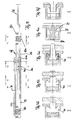
- Figur 5
- veranschaulicht einen längeren Abschnitt der Beschlageinrichtung nach
Figur 1 , mit Schnittebenen B bis F, wobei in denFiguren 5b bis 5f diese Schnitte jeweils dargestellt sind. - Figur 6
- veranschaulicht eine Schrägaufsicht auf einen Ausstellarm 70 auf einer C-förmigen Profilschiene, in welche der Gleiter G eingesetzt sein kann.
- Figur 7, Figur 8
- veranschaulichen Flügel, Rahmen und Anbringung der Feststelleinrichtung 6.
-
Figur 1 veranschaulicht eine Nicht-Bremsstellung des Gleiters G, wobei eine Anstiegsflanke einer Durchdrückung 11 a unmittelbar vor einem Steg 17a steht, zur Weiterbewegung in die Bremsstellung nachFigur 1a . - Die Funktion des Gleiters wird in der Position der
Figur 1 , veranschaulicht in der Schnittdarstellung derFigur 2 besonders deutlich. Er besitzt einen aus bevorzugt Kunststoff, als plastisch verformbarem Werkstoff, gebildeten Rumpfabschnitt 40, in den - im Schnitt gesehen - zwei längs verlaufende Kerben 41,42 eingebracht sind, die mit dem inneren Abstand b1 versehen sind. Jede dieser Kerben hat eine im wesentlichen vertikal ausgerichtete Wand 41.2 bzw. 42.2 und eine stärker geneigt verlaufende Wand 41.1 bzw. 42.1. - Die beiden vertikalen Wände 41.2 und 42.2 begrenzen einen Steg 40a, der aufragt und bevorzugt aus der Oberseite des Profils 15 durch eine durchgehende Öffnung 15e (als Spalt) hervorsteht. Der Steg 40a kann mittig eine weitere Öffnung 50 aufweisen, durch die ein Zapfen 60 gesteckt ist, an den ein Scherenarm 70 drehbar angelenkt ist, wobei der Zapfen 60 oberseitig im Abschnitt 61 verjüngt ausgebildet ist.
- An der C-förmigen Schiene 15 sind oben zwei horizontale Stegabschnitte und zwei vertikal, keilförmig ausgebildete und nach unten gerichtete Stegabschnitte 15a,15a' und 15b, 15b' vorgesehen. Letztere vertikal ausgerichteten Abschnitte greifen in die Kerben 41,42 ein und führen den Gleiter bei seiner Längsbewegung.
- Ein Schienenabschnitt 11 ist unterhalb des Gleiters G berührend an seiner Unterseite 40b platziert und kann durch Ausnehmungen und Kröpfungen bzw. Vertiefungen gesteuert über seine Oberseite Kräfte auf den Gleiter ausüben, wie an den folgenden Figuren ersichtlich.
- Der Abstand der vertikalen Wände 41.2 und 42.2 entspricht b1, welcher Abstand kleiner ist als die Gesamtbreite b des Gleiters, der wiederum in seiner Gesamtbreite geringfügig schmäler ist als der Bauraum innerhalb des als Gehäuse wirkenden C-Profils 15 mit seinen Seitenwänden 15c, 15d.
- Die Länge I des Gleiters ist wesentlich größer als die Breite b, insbesondere mehr als viermal so groß. Die Höhe bestimmt sich nach dem aufragenden Stegabschnitt 40a, welche geringfügig niedriger ist als die Breite und wesentlich niedriger ist als die Länge I. Im spezifischen Beispiel beträgt die Höhe nur zwischen 15% bis 20% der Länge.
- Auf dem Stegabschnitt 40a kann im wesentlichen mittig angeordnet ein im wesentlichen quaderförmiger Aufsatz 40a' angebracht sein, der im Bereich der Bohrung 50 vorgesehen ist und flächig größer ist als diese.
- Die Schiene 11 hebt den Gleiter G mit seinem Körper 40 an, wobei die geneigte Wand 41.1 und 42.1 der jeweiligen Kerbe unmittelbar an dem abragenden keilförmigen Stegabschnitt 15a' bzw. 15b' anliegt und der zugehörige Spalt auf Null reduziert ist. Ein solcher Spalt ist im nicht anliegenden Zustand in
Figur 4 veranschaulicht, und mit Bezugszeichen S.1 und S.2 für die jeweilige Kerbe veranschaulicht. InFigur 2 ist dieser Spalt zu Null geworden, in der Bremsposition mit den wirkenden Kräften F1, F2, F1' und F2'. - Die Flächen 42.1 und 41.1 übertragen Normalkräfte zur Mitte. Durch Anheben F0 des Gleiters wird die Kraft erhöht und somit auch die Reibkräfte bzw. Bremskräfte an der Berührungsstelle der zwei Flächen bzw. des jeweiligen Flächenpaares der jeweiligen Kerbe. Ein Sattel kann über den Mittelsteg gelegt sein und in beide Spalten einragen, zur Vermittlung der Brems- und Haltekräfte.
- Bevorzugt haben die Wände einer jeweiligen Kerbe, also die Wände 41.1 und 41.2 einerseits bzw. die Wände 42.1 und 42.2 einen Winkel zwischen 20° und 40°, im wesentlichen um 30° herum, zwischen sich eingenommen. Bevorzugt ist auch der abwärts ragende Steg 15a' und 15b' in einem solchen Winkel ausgebildet.
- Die entstehende Kraft und das Maß der Anhebung zur Bremsung bzw. zum Halten sind durch die kreuz-schraffierten Bereiche 41 a, 41 b in
Figur 3 verdeutlicht. Ausformung 11a sitzt auf dem Steg 17a auf. - Durch die Keilform wird das C-Profil 15 im oberen Bereich zur Mitte gedrückt (an den vertikalen Flanken 15c,15d, die als Biegestrecke m verwendet sind), um die senkrechten Flächenabschnitte 41.2 und 42.2 zur Anlage an die vertikalen Wandabschnitte der nach unten abragenden Stege drücken zu lassen, wodurch die Verformung der C-Schiene begrenzt wird. Durch den Reibschluss ist die Bremswirkung vorhanden und der Gleiter kann Verschiebekräfte in Längsrichtung aufnehmen (und eine Bewegung sperren).
- Die Schiene 11 ist mit einer Anzahl von Erhöhungen (Vertiefungen) 11 a, 11 ab und 11 b quer zur Längsachse versehen, welche eine Teilung aufweisen. Die Teilung entspricht dem Verstellweg, wobei die Teilung mit Durchbrüchen 16a, 16b im Boden 15f des C-Profils 15 korrespondiert. Die Teilung T ist so bemessen (Teilungsmass), dass die Standardschübe von Getrieben eingesetzt werden können und Ungenauigkeiten bei der Montage kompensiert werden. Die Länge eines Durchbruchs 16a kompensiert gleichzeitig auch unterschiedliche Getriebehübe, wobei auf die Anwendung verwiesen wird, welche die
Figuren 7 und 8 für einen Flügel F mit Profil 2, einen Blendrahmen 1, Scharniere 3, eine Handhabe 4 und einen Zentralverschluss 5 zeigen, hier angewendet mit einem Ausstellarm 70 einer Ausstellanordnung 6, welche in verschiedenen Winkelstellungen nachFigur 8 verdeutlicht ist. In diesen Stellungen können Feststellpositionen, Verschiebepositionen und Bremspositionen eingesetzt werden. - Der Verstellweg kann bei 180° Drehgriff oder bei 90° Drehgriff (Betätigung) definiert sein. Eine maximale Verstellung ergibt sich bei 180°, bei 90° ergibt sich eine Teilung von ½. Die Teilung der Profilschiene 15 kann dem Verstellweg entsprechen.
- Eine Funktion des Feststellens ist wie folgt beschrieben. Wird die Handhabe 4 betätigt, verschiebt sich die Schiene 11. Mit einer Verdickung oder Ausformung 11a, 11b, korrespondierend zur Teilung T, fährt sie bei ihrer Längsbewegung gegen Reststege 17a, 17b, zwischen den Ausnehmungen 16a, 16b. Über eine dort angeordnete Schräge wird die Schiene angehoben und drückt das Gleitbauteil G mit seinem Körper 40 nach aufwärts in Richtung der Öffnung 15e des C-Profils. Eine plastische Verformung des Gleiters, der vorzugsweise aus Kunststoff ausgebildet ist, bildet eine Spannung aus, das C-Profil wird gespannt und erreicht eine Klemmwirkung.
- Die Länge I des Gleiters G bzw. seines Rumpfes 40 ist deutlich länger als eine jeweilige Vertiefung, die sich bei einer Ausformung 11 a oder 11 b in der Schiene 11 ergibt. Somit ist in jeder Position eine Klemmung möglich, ohne dass der Gleiter insgesamt von einer dieser Einformungen (von der Oberseite gesehen) aufgenommen wird.
- Das Lösen der Festlage wird durch Rückdrehen der Handhabe 4 erreicht. Die Schienenerhöhungen 11a, 11b fahren weder in die Ausnehmungen 16a, 16b der C-förmigen Schiene 15, um den Flügel F mit seinem Rahmen 2 wieder drehbar zu steuern. Der Zwischenabschnitt 11ab, zwischen den Ausformungen 11a, 11b gelegen, kommt auf dem Steg 17 zu liegen und bestimmt eine Nicht-Bremsposition (Freigabeposition).
- Vorgeschlagen wird ein Gleiterbauteil für eine Feststellvorrichtung aus Kunststoff oder einem plastisch verformbaren anderen Werkstoff, mit einer größeren Länge (I) als Breite (b), und für eine Anwendung im Beschlagsbereich bei einer Feststellvorrichtung oder einer Ausstellvorrichtung (6), insbesondere mit Verschiebezustand, Übergangsposition von Gleitposition zu Bremsposition und zumindest einer Bremsposition. Der Gleiter hat einen Sockelabschnitt (40) und zwei in Längsrichtung verlaufende Kerben (41, 42), welche zueinander einen Abstand (b1) aufweisen. Der Abstand (b1) ist von einem Stegabschnitt (40a) eingenommen, der sich über ein Mehrfaches seiner Breite (b1) in Axialrichtung erstreckt.
Claims (27)
- Feststellvorrichtung mit längs-beweglichen Gleiterbauteil (G), um einen- gewünschten - Öffnungswinkel eines Flügels (F) mit einem, durch einen Handgriff (4) in wenigstens zwei Stellungen bewegbaren, in einer Beschlagsnut eines Rahmens (2) des Flügels verdeckt anbringbaren Betätigungsgestänge (5) einzustellen, wobei der Gleiterbauteil (G)- einen in einer Führungsschiene (15) gleitend längs-verschiebbaren Rumpfabschnitt (40) aufweist, der zwischen einem Stangenabschnitt (11;11a,11b,11ab) und zwei Randflanschen (15a,15a';15b,15b') der Führungsschiene geführt ist und ausgebildet ist, ein Ende eines Lenkers (70) daran zu koppeln, wobei ein anderes Ende des Lenkers (70) im Abstand von einer Flügelachse an einem Blendrahmen anlenkbar ist;dadurch gekennzeichnet, dass- ein Boden (15f) der Führungsschiene (15) in deren Längsrichtung nach einem vorbestimmten Teilungsmaß (T) angeordnete Längsfenster (16a,16b) aufweist, die durch Bodenstege (11a,17b) voneinander beabstandet sind, und der Stangenabschnitt (11) nach dem gleichen Teilungsmaß über seine Länge verteilte oberseitige Vertiefungen (11a,11b) aufweist, deren unterseitige Ausformungen in Abhängigkeit von der relativen Lage des Stangenabschnitts (11) gegenüber dem Boden (15f) in die Längsfenster eingreifen oder auf den Bodenstegen aufsitzen;- eine lichte Höhe zwischen den Bodenstegen und einer Unterseite der Randflansche (15a,15a';15b,15b') und eine Gesamthöhe des Stangenabschnitts (11) im Bereich der unterseitigen Ausformungen sowie eine Höhe von Schulterflächen (41.1,41.2;42.1,42.2) am Rumpfabschnitt des Gleiterbauteils (G) einander abgestimmt sind, um
bei einem Aufgleiten einer Ausformung auf einen
Bodensteg das Gleiterbauteil mit seinen Schulterflächen
an den Randflanschen (15a,15a'; 15b,15b') der
Führungsschiene festzusetzen. - Feststellvorrichtung nach Anspruch 1, wobei die Randflansche (15a,15b) an ihrer Unterseite eine oder mehrere in Längsrichtung der Führungsschiene verlaufende Längsstege (15a',15b') aufweisen.
- Feststellvorrichtung nach Anspruch 1 oder 2, wobei die Schulterflächen (41;41.1,41.2) durch in Längsrichtung der Führungsschiene (15) orientierte Profilierungen gebildet werden.
- Feststellvorrichtung nach einem der voranstehenden Ansprüche, wobei wenigstens der untere, mit dem Stangenabschnitt (11) zusammenwirkende Bereich oder Abschnitt des Gleiterbauteils (G) aus einem Kunststoff besteht.
- Feststellvorrichtung nach Anspruch 1, wobei das Gleiterbauteil (G) zweiteilig ausgebildet ist und der obere, die profilierten Schulterflächen aufweisende Abschnitt aus Metall besteht und formschlüssig und über einen beide Abschnitte durchgreifenden Anlenkzapfen (60,61) für den Lenker (70) mit einem unteren Kunststoffabschnitt verbunden ist.
- Feststellvorrichtung nach Anspruch 1, wobei eine Betätigungsrichtung des Stangenabschnitts (11) in beiden Richtungen, von rechts nach links und umgekehrt, möglich ist.
- Feststellvorrichtung nach Anspruch 1, wobei der Stangenabschnitt (11) einen ablängbaren Bereich (11c) aufweist, zur Kopplung an eine Eckumlenkung.
- Feststellvorrichtung nach Anspruch 1, wobei die Führungsschiene (15) ein Profil ist, geeignet oder passend für eine Beschlagsnut ohne Nacharbeit.
- Feststellvorrichtung nach einem der voranstehenden Ansprüche, wobei ein Sattelbauteil (80) vorgesehen ist, welches zur Befestigung und Lastaufnahme der Führungsschiene (15) in einer Beschlagsnut geeignet ist.
- Feststellvorrichtung nach Anspruch 1, wobei im Wesentlichen in einer Mitte der axialen Erstreckung des Stegs eine Öffnung (50) für eine drehfähige Montage eines Lenkers vorgesehen ist.
- Feststellvorrichtung nach Anspruch 1, wobei im Gleiterbauteil Kerben (41,42) vorgesehen sind.
- Feststellvorrichtung nach Anspruch 11, wobei die Kerben (41,42) im wesentlichen V-Form haben.
- Feststellvorrichtung nach Anspruch 11, wobei die Kerben so angepasst sind, dass sie an einer C-förmigen Profilschiene (15) mit keilförmig eingreifenden Stegen (15a',15b') an den Randflanschen (15a,15a';15b,15b') das Gleiterbauteil (G) führen, zur verschiebbaren Fixierung des Gleiterbauteils.
- Feststellvorrichtung nach Anspruch 11, wobei die Kerben über die ganze Länge (l) des Gleiterbauteils (G) verlaufen.
- Feststellvorrichtung nach Anspruch 11, wobei ein Abstand (b1) der Kerben im Gleiterbauteil (G) größer ist als eine maximale Breite der Kerben (41,42).
- Feststellvorrichtung nach Anspruch 3, wobei die Profilierungen als Kerben (41,42) ausgebildet sind.
- Feststellvorrichtung nach Anspruch 1 oder 2, wobei die Schulterflächen durch in Längsrichtung der Führungsschiene (15) orientierte Profilierungen (41,42) gebildet werden und zwei solcher Flächen (41;41.1,41.2) je Profilierung vorgesehen sind.
- Feststellvorrichtung nach Anspruch 4, wobei der untere Bereich oder Abschnitt des Gleiterbauteils aus einem verschleißfesten Kunststoff besteht.
- Feststellvorrichtung nach Anspruch 7, wobei der ablängbare Bereich (11c) zur Kopplung an eine Eckumlenkung als randseitig zumindest abschnittsweise verzahntes Flachstück vorgesehen ist.
- Feststellvorrichtung nach Anspruch 1, wobei das Profil (15) einen Boden (15f) und Randflansche (15c,15d) aufweist, geeignet oder passend für die Beschlagsnut ohne Nacharbeit.
- Feststellvorrichtung nach Anspruch 8, wobei die Führungsschiene (15) als C-förmiges Profil ausgebildet ist, geeignet oder passend für die Beschlagsnut ohne Nacharbeit.
- Feststellvorrichtung nach Anspruch 12, wobei eine der Wände der V-Form stärker geneigt ist, als der andere Wandabschnitt derselben V-förmigen Kerbe.
- Gleiterbauteil aus bevorzugt Kunststoff oder einem plastisch verformbaren anderen Werkstoff, verwendbar in der Feststellvorrichtung nach Anspruch 1, um einen - gewünschten - Öffnungswinkel eines Flügels (F) mit einem, durch einen Handgriff (4) in wenigstens zwei Stellungen bewegbaren, in einer Beschlagsnut eines Rahmens (2) des Flügels verdeckt anbringbaren Betätigungsgestänge (5) einzustellen;
wobei der Gleiterbauteil (G) mit einer größeren Länge (l) als Breite (b) versehen ist, für die Anwendung im Beschlagsbereich bei der Feststellvorrichtung oder einer Ausstellvorrichtung (6), der Gleiterbauteil (G) mit Verschiebezustand, Übergangsposition von Gleitposition zu Bremsposition und zumindest einer Bremsposition,(a) wobei der Gleiterbauteil (G) einen Rumpf- oder Sockelabschnitt (40) und zwei in Längsrichtung verlaufende Kerben (41,42) aufweist, die zueinander einen Abstand (b1) haben;(b) wobei der Abstand (b1) von einem Stegabschnitt (40a) eingenommen wird, der sich über ein Mehrfaches seiner Breite (b1) in axialer Längsrichtung erstreckt;
dadurch gekennzeichnet, dass(c) die Kerben (41,42) nach aufwärts ragen oder nach oben offen sind, und im wesentlichen V-Form haben. - Gleiterbauteil nach Anspruch 23, wobei im Wesentlichen in einer Mitte der axialen Erstreckung des Stegs eine Öffnung (50) für eine drehfähige Montage eines Lenkers vorgesehen ist.
- Gleiterbauteil nach Anspruch 23, wobei eine der Wände der V-Form stärker geneigt ist, als der andere Wandabschnitt derselben V-Kerbe.
- Gleiterbauteil nach Anspruch 23 oder 25, wobei die Kerben zur verschiebbaren Fixierung des Gleiterbauteils (G) so angepasst sind, dass sie von einer C-förmigen Profilschiene als Führungsschiene (15) mit keilförmig eingreifenden Stegen (15a',15b') geführt werden.
- Gleiterbauteil nach Anspruch 23, wobei die Kerben (41,42) über die ganze Länge (l) des Sockelabschnitts (40) verlaufen und/oder der Abstand (b1)der Kerben größer ist als die maximale Breite der Kerben.
Priority Applications (2)
| Application Number | Priority Date | Filing Date | Title |
|---|---|---|---|
| EP05102079A EP1577472B1 (de) | 2004-03-16 | 2005-03-16 | Gleiterbauteil und Feststell- oder Austellvorrichtung für den Beschlag von Fensternflügeln |
| PL05102079T PL1577472T3 (pl) | 2004-03-16 | 2005-03-16 | Ślizgowy element konstrukcyjny oraz urządzenie ustalające i otwierające, przeznaczone dla okucia skrzydeł okiennych |
Applications Claiming Priority (3)
| Application Number | Priority Date | Filing Date | Title |
|---|---|---|---|
| EP04006214 | 2004-03-16 | ||
| EP04006214 | 2004-03-16 | ||
| EP05102079A EP1577472B1 (de) | 2004-03-16 | 2005-03-16 | Gleiterbauteil und Feststell- oder Austellvorrichtung für den Beschlag von Fensternflügeln |
Publications (3)
| Publication Number | Publication Date |
|---|---|
| EP1577472A2 EP1577472A2 (de) | 2005-09-21 |
| EP1577472A3 EP1577472A3 (de) | 2007-04-18 |
| EP1577472B1 true EP1577472B1 (de) | 2008-11-26 |
Family
ID=40092837
Family Applications (1)
| Application Number | Title | Priority Date | Filing Date |
|---|---|---|---|
| EP05102079A Expired - Lifetime EP1577472B1 (de) | 2004-03-16 | 2005-03-16 | Gleiterbauteil und Feststell- oder Austellvorrichtung für den Beschlag von Fensternflügeln |
Country Status (5)
| Country | Link |
|---|---|
| EP (1) | EP1577472B1 (de) |
| AT (1) | ATE415535T1 (de) |
| DE (1) | DE502005006034D1 (de) |
| DK (1) | DK1577472T3 (de) |
| PL (1) | PL1577472T3 (de) |
Families Citing this family (4)
| Publication number | Priority date | Publication date | Assignee | Title |
|---|---|---|---|---|
| PL1876319T3 (pl) * | 2006-07-06 | 2015-04-30 | Hautau Gmbh | Prowadnica ślizgowa dla skrzydeł przesuwnych albo skrzydeł przesuwnych z równoległym odstawieniem |
| PL217926B1 (pl) | 2008-01-14 | 2014-09-30 | Jacek Głogowski | Urządzenie do blokowania/hamowania przesuwu lub obrotu z zabezpieczeniem przeciążeniowym |
| RS59234B1 (sr) * | 2014-04-04 | 2019-10-31 | Fapim S P A | Uređaj za otvaranje/zatvaranje prozora sa elementom za zaustavljanje krila prozora u otvorenom položaju |
| CN112377018A (zh) * | 2020-11-11 | 2021-02-19 | 泰州市爱利特金属制品有限公司 | 一种窗用铰链 |
Family Cites Families (4)
| Publication number | Priority date | Publication date | Assignee | Title |
|---|---|---|---|---|
| CH688723A5 (de) * | 1994-08-19 | 1998-01-30 | Rudolf Boog | Halteorgan, insbesondere Ausstellschere, für Kipp-, Drehkipp- oder Schiebekippfenster. |
| DE19516588C1 (de) * | 1995-05-05 | 1996-09-19 | Weidtmann Wilhelm Kg | Feststellvorrichtung für Fenster, Türen od. dgl. |
| FI100548B (fi) * | 1996-09-02 | 1997-12-31 | Abloy Oy | Oven aukipitolaite |
| DE19960117A1 (de) * | 1999-12-14 | 2001-06-21 | Winkhaus Fa August | Bremseinrichtung für einen schwenkbaren Flügel |
-
2005
- 2005-03-16 DE DE502005006034T patent/DE502005006034D1/de not_active Expired - Lifetime
- 2005-03-16 AT AT05102079T patent/ATE415535T1/de active
- 2005-03-16 PL PL05102079T patent/PL1577472T3/pl unknown
- 2005-03-16 DK DK05102079T patent/DK1577472T3/da active
- 2005-03-16 EP EP05102079A patent/EP1577472B1/de not_active Expired - Lifetime
Also Published As
| Publication number | Publication date |
|---|---|
| EP1577472A2 (de) | 2005-09-21 |
| ATE415535T1 (de) | 2008-12-15 |
| PL1577472T3 (pl) | 2009-04-30 |
| DK1577472T3 (da) | 2009-03-23 |
| EP1577472A3 (de) | 2007-04-18 |
| DE502005006034D1 (de) | 2009-01-08 |
Similar Documents
| Publication | Publication Date | Title |
|---|---|---|
| DE69705662T2 (de) | Rollvorrichtung für Schiebetüren, Fenster oder ähnliches | |
| EP3452680B1 (de) | Dichtungsvorrichtung | |
| DE202022100517U1 (de) | Profilanordnung eines Fensters oder einer Tür mit einem Flügelprofil, insbesondere einem Schiebeflügelprofil | |
| DE20115938U1 (de) | Laufwagenanordnung eines Beschlages für Hebe-Schiebe-Türen oder -Fenster sowie Beschlag mit einer solchen Laufwagenanordnung | |
| EP0718456A1 (de) | Fenster, Tür, od. ähnlicher Öffnungsverschluss | |
| DE102010061173B3 (de) | Schmale Drei-Wege-Steuervorrichtung zur Steuerung einer Parallel-Abstellung eines Tür- oder Fensterflügels | |
| DE3033751C2 (de) | Beschlag für den Schiebeflügel von Fenstern, Türen oder dgl. aus Holz- oder Kunststoffprofilen | |
| EP3859110A1 (de) | Schiebetürbeschlag und verfahren zum bewegen einer steuereinrichtung | |
| EP1577472B1 (de) | Gleiterbauteil und Feststell- oder Austellvorrichtung für den Beschlag von Fensternflügeln | |
| EP4473180A1 (de) | Verlagerungsvorrichtung zur zwangsweisen verlagerung eines flügels, insbesondere eines schiebeflügels, eines fensters oder einer tür | |
| EP3112577A1 (de) | Absenkdichtung | |
| DE202022100514U1 (de) | Verlagerungsvorrichtung zur zwangsweisen Verlagerung eines Flügels, insbesondere eines Schiebeflügels, eines Fensters oder einer Tür | |
| EP3162995B1 (de) | Beschlagteil eines beschlages für einen flügel eines fensters oder einer tür | |
| DE3334298C2 (de) | ||
| DE2227735A1 (de) | Vorrichtung zum andruecken und abheben eines ebenen, verschiebbaren elements an bzw. von einem rahmen | |
| EP1522666B1 (de) | Beschlag für Hebe-Schiebe-Türen oder -Fenster sowie Laufschuh für einen solchen Beschlag | |
| CH628390A5 (en) | Vertical sash window | |
| DE102018100550A1 (de) | Führungsgleiter für ein schiebetür- und/oder schiebefenstersystem, beweglicher schieberahmen mit einem führungsgleiter sowie schiebetür- und/oder schiebefenstersystem mit führungsleiter | |
| DE1976119U (de) | Verschlussvorrichtung fuer die fluegel von fenstern, tueren od. dgl. | |
| EP2267257B1 (de) | Feststellvorrichtung | |
| DE20306960U1 (de) | Beschlageinheit für Fenster oder Türen | |
| EP4039925B1 (de) | Flügelanordnung | |
| EP3816383A1 (de) | Schiebetüranordnung | |
| DE20316289U1 (de) | Beschlag für Hebe-Schiebe-Türen oder -Fenster | |
| CH618764A5 (en) | Fitting for actuating a tilt-and-slide wing of windows or doors |
Legal Events
| Date | Code | Title | Description |
|---|---|---|---|
| PUAI | Public reference made under article 153(3) epc to a published international application that has entered the european phase |
Free format text: ORIGINAL CODE: 0009012 |
|
| AK | Designated contracting states |
Kind code of ref document: A2 Designated state(s): AT BE BG CH CY CZ DE DK EE ES FI FR GB GR HU IE IS IT LI LT LU MC NL PL PT RO SE SI SK TR |
|
| AX | Request for extension of the european patent |
Extension state: AL BA HR LV MK YU |
|
| RAP1 | Party data changed (applicant data changed or rights of an application transferred) |
Owner name: HAUTAU GMBH |
|
| RAP1 | Party data changed (applicant data changed or rights of an application transferred) |
Owner name: HAUTAU GMBH |
|
| PUAL | Search report despatched |
Free format text: ORIGINAL CODE: 0009013 |
|
| AK | Designated contracting states |
Kind code of ref document: A3 Designated state(s): AT BE BG CH CY CZ DE DK EE ES FI FR GB GR HU IE IS IT LI LT LU MC NL PL PT RO SE SI SK TR |
|
| AX | Request for extension of the european patent |
Extension state: AL BA HR LV MK YU |
|
| 17P | Request for examination filed |
Effective date: 20070510 |
|
| 17Q | First examination report despatched |
Effective date: 20070629 |
|
| AKX | Designation fees paid |
Designated state(s): AT BE BG CH CY CZ DE DK EE ES FI FR GB GR HU IE IS IT LI LT LU MC NL PL PT RO SE SI SK TR |
|
| GRAP | Despatch of communication of intention to grant a patent |
Free format text: ORIGINAL CODE: EPIDOSNIGR1 |
|
| GRAS | Grant fee paid |
Free format text: ORIGINAL CODE: EPIDOSNIGR3 |
|
| GRAA | (expected) grant |
Free format text: ORIGINAL CODE: 0009210 |
|
| AK | Designated contracting states |
Kind code of ref document: B1 Designated state(s): AT BE BG CH CY CZ DE DK EE ES FI FR GB GR HU IE IS IT LI LT LU MC NL PL PT RO SE SI SK TR |
|
| REG | Reference to a national code |
Ref country code: GB Ref legal event code: FG4D Free format text: NOT ENGLISH |
|
| REG | Reference to a national code |
Ref country code: CH Ref legal event code: EP |
|
| REG | Reference to a national code |
Ref country code: IE Ref legal event code: FG4D Free format text: LANGUAGE OF EP DOCUMENT: GERMAN |
|
| REF | Corresponds to: |
Ref document number: 502005006034 Country of ref document: DE Date of ref document: 20090108 Kind code of ref document: P |
|
| REG | Reference to a national code |
Ref country code: CH Ref legal event code: NV Representative=s name: KELLER & PARTNER PATENTANWAELTE AG |
|
| REG | Reference to a national code |
Ref country code: SE Ref legal event code: TRGR |
|
| REG | Reference to a national code |
Ref country code: DK Ref legal event code: T3 |
|
| PG25 | Lapsed in a contracting state [announced via postgrant information from national office to epo] |
Ref country code: ES Free format text: LAPSE BECAUSE OF FAILURE TO SUBMIT A TRANSLATION OF THE DESCRIPTION OR TO PAY THE FEE WITHIN THE PRESCRIBED TIME-LIMIT Effective date: 20090308 |
|
| REG | Reference to a national code |
Ref country code: PL Ref legal event code: T3 |
|
| PG25 | Lapsed in a contracting state [announced via postgrant information from national office to epo] |
Ref country code: FI Free format text: LAPSE BECAUSE OF FAILURE TO SUBMIT A TRANSLATION OF THE DESCRIPTION OR TO PAY THE FEE WITHIN THE PRESCRIBED TIME-LIMIT Effective date: 20081126 Ref country code: SI Free format text: LAPSE BECAUSE OF FAILURE TO SUBMIT A TRANSLATION OF THE DESCRIPTION OR TO PAY THE FEE WITHIN THE PRESCRIBED TIME-LIMIT Effective date: 20081126 Ref country code: IS Free format text: LAPSE BECAUSE OF FAILURE TO SUBMIT A TRANSLATION OF THE DESCRIPTION OR TO PAY THE FEE WITHIN THE PRESCRIBED TIME-LIMIT Effective date: 20090326 |
|
| REG | Reference to a national code |
Ref country code: IE Ref legal event code: FD4D |
|
| PG25 | Lapsed in a contracting state [announced via postgrant information from national office to epo] |
Ref country code: BG Free format text: LAPSE BECAUSE OF FAILURE TO SUBMIT A TRANSLATION OF THE DESCRIPTION OR TO PAY THE FEE WITHIN THE PRESCRIBED TIME-LIMIT Effective date: 20090226 Ref country code: EE Free format text: LAPSE BECAUSE OF FAILURE TO SUBMIT A TRANSLATION OF THE DESCRIPTION OR TO PAY THE FEE WITHIN THE PRESCRIBED TIME-LIMIT Effective date: 20081126 Ref country code: RO Free format text: LAPSE BECAUSE OF FAILURE TO SUBMIT A TRANSLATION OF THE DESCRIPTION OR TO PAY THE FEE WITHIN THE PRESCRIBED TIME-LIMIT Effective date: 20081126 Ref country code: IE Free format text: LAPSE BECAUSE OF FAILURE TO SUBMIT A TRANSLATION OF THE DESCRIPTION OR TO PAY THE FEE WITHIN THE PRESCRIBED TIME-LIMIT Effective date: 20081126 |
|
| PG25 | Lapsed in a contracting state [announced via postgrant information from national office to epo] |
Ref country code: PT Free format text: LAPSE BECAUSE OF FAILURE TO SUBMIT A TRANSLATION OF THE DESCRIPTION OR TO PAY THE FEE WITHIN THE PRESCRIBED TIME-LIMIT Effective date: 20090427 Ref country code: CZ Free format text: LAPSE BECAUSE OF FAILURE TO SUBMIT A TRANSLATION OF THE DESCRIPTION OR TO PAY THE FEE WITHIN THE PRESCRIBED TIME-LIMIT Effective date: 20081126 |
|
| PG25 | Lapsed in a contracting state [announced via postgrant information from national office to epo] |
Ref country code: SK Free format text: LAPSE BECAUSE OF FAILURE TO SUBMIT A TRANSLATION OF THE DESCRIPTION OR TO PAY THE FEE WITHIN THE PRESCRIBED TIME-LIMIT Effective date: 20081126 |
|
| PLBE | No opposition filed within time limit |
Free format text: ORIGINAL CODE: 0009261 |
|
| STAA | Information on the status of an ep patent application or granted ep patent |
Free format text: STATUS: NO OPPOSITION FILED WITHIN TIME LIMIT |
|
| PG25 | Lapsed in a contracting state [announced via postgrant information from national office to epo] |
Ref country code: MC Free format text: LAPSE BECAUSE OF NON-PAYMENT OF DUE FEES Effective date: 20090331 |
|
| 26N | No opposition filed |
Effective date: 20090827 |
|
| PG25 | Lapsed in a contracting state [announced via postgrant information from national office to epo] |
Ref country code: GR Free format text: LAPSE BECAUSE OF FAILURE TO SUBMIT A TRANSLATION OF THE DESCRIPTION OR TO PAY THE FEE WITHIN THE PRESCRIBED TIME-LIMIT Effective date: 20090227 |
|
| PG25 | Lapsed in a contracting state [announced via postgrant information from national office to epo] |
Ref country code: IT Free format text: LAPSE BECAUSE OF FAILURE TO SUBMIT A TRANSLATION OF THE DESCRIPTION OR TO PAY THE FEE WITHIN THE PRESCRIBED TIME-LIMIT Effective date: 20081126 |
|
| PG25 | Lapsed in a contracting state [announced via postgrant information from national office to epo] |
Ref country code: LU Free format text: LAPSE BECAUSE OF NON-PAYMENT OF DUE FEES Effective date: 20090316 |
|
| PG25 | Lapsed in a contracting state [announced via postgrant information from national office to epo] |
Ref country code: HU Free format text: LAPSE BECAUSE OF FAILURE TO SUBMIT A TRANSLATION OF THE DESCRIPTION OR TO PAY THE FEE WITHIN THE PRESCRIBED TIME-LIMIT Effective date: 20090527 |
|
| PG25 | Lapsed in a contracting state [announced via postgrant information from national office to epo] |
Ref country code: TR Free format text: LAPSE BECAUSE OF FAILURE TO SUBMIT A TRANSLATION OF THE DESCRIPTION OR TO PAY THE FEE WITHIN THE PRESCRIBED TIME-LIMIT Effective date: 20081126 |
|
| PGFP | Annual fee paid to national office [announced via postgrant information from national office to epo] |
Ref country code: PL Payment date: 20110314 Year of fee payment: 7 |
|
| PG25 | Lapsed in a contracting state [announced via postgrant information from national office to epo] |
Ref country code: CY Free format text: LAPSE BECAUSE OF FAILURE TO SUBMIT A TRANSLATION OF THE DESCRIPTION OR TO PAY THE FEE WITHIN THE PRESCRIBED TIME-LIMIT Effective date: 20081126 |
|
| PGFP | Annual fee paid to national office [announced via postgrant information from national office to epo] |
Ref country code: CH Payment date: 20120315 Year of fee payment: 8 Ref country code: FR Payment date: 20120410 Year of fee payment: 8 Ref country code: LT Payment date: 20120306 Year of fee payment: 8 |
|
| PGFP | Annual fee paid to national office [announced via postgrant information from national office to epo] |
Ref country code: DK Payment date: 20120315 Year of fee payment: 8 Ref country code: BE Payment date: 20120315 Year of fee payment: 8 Ref country code: SE Payment date: 20120322 Year of fee payment: 8 Ref country code: GB Payment date: 20120326 Year of fee payment: 8 |
|
| PGFP | Annual fee paid to national office [announced via postgrant information from national office to epo] |
Ref country code: NL Payment date: 20120322 Year of fee payment: 8 Ref country code: DE Payment date: 20120529 Year of fee payment: 8 |
|
| PGFP | Annual fee paid to national office [announced via postgrant information from national office to epo] |
Ref country code: AT Payment date: 20120328 Year of fee payment: 8 |
|
| BERE | Be: lapsed |
Owner name: HAUTAU G.M.B.H. Effective date: 20130331 |
|
| REG | Reference to a national code |
Ref country code: NL Ref legal event code: V1 Effective date: 20131001 |
|
| REG | Reference to a national code |
Ref country code: LT Ref legal event code: MM4D Effective date: 20130316 |
|
| REG | Reference to a national code |
Effective date: 20130331 Ref country code: DK Ref legal event code: EBP |
|
| REG | Reference to a national code |
Ref country code: SE Ref legal event code: EUG |
|
| PG25 | Lapsed in a contracting state [announced via postgrant information from national office to epo] |
Ref country code: LT Free format text: LAPSE BECAUSE OF NON-PAYMENT OF DUE FEES Effective date: 20130316 Ref country code: SE Free format text: LAPSE BECAUSE OF NON-PAYMENT OF DUE FEES Effective date: 20130317 |
|
| REG | Reference to a national code |
Ref country code: CH Ref legal event code: PL |
|
| REG | Reference to a national code |
Ref country code: AT Ref legal event code: MM01 Ref document number: 415535 Country of ref document: AT Kind code of ref document: T Effective date: 20130316 |
|
| GBPC | Gb: european patent ceased through non-payment of renewal fee |
Effective date: 20130316 |
|
| REG | Reference to a national code |
Ref country code: FR Ref legal event code: ST Effective date: 20131129 |
|
| REG | Reference to a national code |
Ref country code: DE Ref legal event code: R119 Ref document number: 502005006034 Country of ref document: DE Effective date: 20131001 |
|
| PG25 | Lapsed in a contracting state [announced via postgrant information from national office to epo] |
Ref country code: DE Free format text: LAPSE BECAUSE OF NON-PAYMENT OF DUE FEES Effective date: 20131001 Ref country code: LI Free format text: LAPSE BECAUSE OF NON-PAYMENT OF DUE FEES Effective date: 20130331 Ref country code: BE Free format text: LAPSE BECAUSE OF NON-PAYMENT OF DUE FEES Effective date: 20130331 Ref country code: AT Free format text: LAPSE BECAUSE OF NON-PAYMENT OF DUE FEES Effective date: 20130316 Ref country code: CH Free format text: LAPSE BECAUSE OF NON-PAYMENT OF DUE FEES Effective date: 20130331 Ref country code: GB Free format text: LAPSE BECAUSE OF NON-PAYMENT OF DUE FEES Effective date: 20130316 Ref country code: FR Free format text: LAPSE BECAUSE OF NON-PAYMENT OF DUE FEES Effective date: 20130402 |
|
| PG25 | Lapsed in a contracting state [announced via postgrant information from national office to epo] |
Ref country code: NL Free format text: LAPSE BECAUSE OF NON-PAYMENT OF DUE FEES Effective date: 20131001 |
|
| PG25 | Lapsed in a contracting state [announced via postgrant information from national office to epo] |
Ref country code: DK Free format text: LAPSE BECAUSE OF NON-PAYMENT OF DUE FEES Effective date: 20130331 |
|
| PG25 | Lapsed in a contracting state [announced via postgrant information from national office to epo] |
Ref country code: PL Free format text: LAPSE BECAUSE OF NON-PAYMENT OF DUE FEES Effective date: 20130316 |
|
| REG | Reference to a national code |
Ref country code: PL Ref legal event code: LAPE |