EP1577469B1 - Schlüssel - Google Patents
Schlüssel Download PDFInfo
- Publication number
- EP1577469B1 EP1577469B1 EP05101380A EP05101380A EP1577469B1 EP 1577469 B1 EP1577469 B1 EP 1577469B1 EP 05101380 A EP05101380 A EP 05101380A EP 05101380 A EP05101380 A EP 05101380A EP 1577469 B1 EP1577469 B1 EP 1577469B1
- Authority
- EP
- European Patent Office
- Prior art keywords
- key
- lock
- tip
- pitch
- lock cylinder
- Prior art date
- Legal status (The legal status is an assumption and is not a legal conclusion. Google has not performed a legal analysis and makes no representation as to the accuracy of the status listed.)
- Expired - Lifetime
Links
- 238000003780 insertion Methods 0.000 claims abstract description 28
- 230000037431 insertion Effects 0.000 claims abstract description 28
- 239000007787 solid Substances 0.000 description 6
- 101100289200 Caenorhabditis elegans lite-1 gene Proteins 0.000 description 1
- 241001295925 Gegenes Species 0.000 description 1
- 230000000903 blocking effect Effects 0.000 description 1
- 230000003252 repetitive effect Effects 0.000 description 1
- 230000002441 reversible effect Effects 0.000 description 1
- 238000000926 separation method Methods 0.000 description 1
Images


Classifications
-
- E—FIXED CONSTRUCTIONS
- E05—LOCKS; KEYS; WINDOW OR DOOR FITTINGS; SAFES
- E05B—LOCKS; ACCESSORIES THEREFOR; HANDCUFFS
- E05B19/00—Keys; Accessories therefor
- E05B19/0017—Key profiles
-
- E—FIXED CONSTRUCTIONS
- E05—LOCKS; KEYS; WINDOW OR DOOR FITTINGS; SAFES
- E05B—LOCKS; ACCESSORIES THEREFOR; HANDCUFFS
- E05B17/00—Accessories in connection with locks
- E05B17/007—Devices for reducing friction between lock parts
-
- E—FIXED CONSTRUCTIONS
- E05—LOCKS; KEYS; WINDOW OR DOOR FITTINGS; SAFES
- E05B—LOCKS; ACCESSORIES THEREFOR; HANDCUFFS
- E05B19/00—Keys; Accessories therefor
- E05B19/0017—Key profiles
- E05B19/0041—Key profiles characterized by the cross-section of the key blade in a plane perpendicular to the longitudinal axis of the key
- E05B19/0052—Rectangular flat keys
- E05B19/0058—Rectangular flat keys with key bits on at least one wide side surface of the key
Definitions
- the invention relates to a key for a locking cylinder comprising a series of pin tumblers having a shank with a series of locking recesses arranged in the shank and cooperating with the pin tumblers, the locking recesses being spaced from each other by a predetermined pitch and one at the free end thereof arranged, an insertion bevel having key tip, wherein the insertion bevel of the key tip outside the grid dimension (a) of the closing recesses is arranged.
- a key of the type mentioned is, for example, from the DE 197 45 834 A1 known.
- the key tip as well as stop means and the locking recesses on an offset.
- the offset allows the use of the key as a reversible key, without significantly weakened by opposing locking recesses of the shaft.
- the locking recesses contain with a step measure a locking secret, which corresponds to the number of pin tumblers of the key.
- the insertion tip arranged on the key tip presses the pin tumblers out of the closing channel when the key is inserted into a closing channel of the lock cylinder.
- the key has a high degree of locking comfort when inserting the key into the lock cylinder.
- the locking recesses reach the height of the pin tumblers.
- housing pins of the pin tumblers are fully pressed into a housing while core pins of the pin tumblers remain in a core of the lock cylinder.
- all separation planes of the core pins and the housing pins lie in the parting plane between the housing and the core, so that the core can be moved relative to the housing.
- the lock channel for receiving the key is open to the shell of the core. Upon rotation of the core with the key fully inserted, the spine prevents the housing pins from entering the closing channel.
- the disadvantage of the key from the DE 35 17 660 A1 is that the insertion bevel on the key tip can move one of the pin tumblers in the parting plane between the housing and core.
- the pin tumbler which is located deepest in the closing channel, can be moved by the insertion bevel and the remaining pin tumblers can be moved from the wrong closing cutouts into the unlocking position.
- the lock cylinder is unlocked without the key is fully inserted. This is the case, for example, when adjacent pin tumblers have the same step size or repetitive step measures, and the last pin tumbler, which is located deepest in the lock channel, randomly has a step dimension corresponding to the key tip.
- the pin tumblers release the movement of the core relative to the housing, although the key is not fully inserted into the lock channel is.
- the core can then be slightly twisted and blocked because the core pin of the last pin tumbler on the side of the key back penetrates into the closing channel. After blocking, the lock cylinder can no longer be actuated and the key can not be pulled out of the lock channel.
- the invention is based on the problem to design a key of the type mentioned so that it allows unlocking of the lock cylinder only after a complete insertion into the lock channel and that the key is particularly easy to insert into the lock channel.
- the insertion has a steeply inclined in the longitudinal direction of the shaft first portion and a subsequent to the sharply inclined first portion slightly inclined second portion.
- the insertion bevel has a first section strongly inclined in the longitudinal direction of the shank and a slightly inclined second section adjoining the steeply inclined first section.
- actuation of the last closing recess by the key tip can be reliably avoided if the distance of the free end of the key tip from the next closing recess is smaller than the spacing of the closing recesses. This avoids that the pin tumbler which is arranged deepest in the closing channel is actuated at all if the key according to the invention has not been introduced enough into the closing channel by one pitch.
- a smooth insertion of the key according to the invention in the closing channel can be according to another advantageous embodiment of the invention can be easily achieved if the insertion has a deviating from the locking recesses contour. At the same time thereby the risk of actuation of a locking recess is reduced by the key tip.
- the key according to the invention reliably avoids the simultaneous actuation of the last pin tumblers in the case of lock cylinders with a plurality of rows of closing tumblers. when two opposite rows of locking recesses opposite insertion chamfers are offset from each other.
- the key according to the invention is structurally particularly simple if, in the case of several rows of closing recesses, only one of the insertion bevels is arranged outside the grid dimension a.
- the key is in FIG. 2 completely inserted into the lock channel 3, so that a shoulder 13 of the key 4 abuts a shoulder 14 of the core 2.
- a key tip 15 of the key 4 has the rows of pin tumblers 7 facing chamfers 16.
- the pin tumblers 7, 7 'and thus also the locking recesses 12 are spaced from each other by an intended pitch a.
- the key tip 15 points from the next Sch.aus originallyung 7, 7 'a smaller distance than the grid a.
- FIG. 4 shows a further example of a not belonging to the invention key 4, in which between a key tip 17 and the next closing recess 12, a solid profile section 18 is arranged.
- the solid profile section 18 between the key tip 17 and the last closing recess 12 is guided to a spaced by the pitch a from the last locking recess 12 point. If you turn the key 4 off FIG. 4 to the grid dimension a too little in the closing channel 3 of the lock cylinder after FIG. 2 introduces the pin tumbler 7 'located deepest in the lock channel 3 on the solid profile section 18. This allows the pin tumbler 7' located deepest in the lock channel 3 not to release the movement of the core 2. Thus, the pin tumblers located deepest in the closing channel 3 prevent the unlocking of the lock cylinder.
- FIG. 5 shows an embodiment according to the invention of the key 4, in which a first insertion bevel 19 a in the longitudinal direction of the shaft 11 strongly inclined first portion 20 and a subsequent to the first portion 20 low having inclined second portion 21.
- a second insertion bevel 22 is also arranged offset relative to the first insertion bevel 19. However, both chamfers 19, 22 are outside the grid a.
- only one of the insertion bevels 19, 22 may be arranged outside the grid dimension a in the case of two rows of pin tumblers 7 associated with the closing cutouts 12.
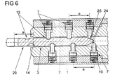
- FIG. 6 shows one in the lock cylinder after FIG. 2 introduced key 23 according to the prior art.
- the key 23 has the same arrangement of locking recesses 12 as the key 4 after the FIGS. 1 to 5 and is able to close the lock cylinder completely in the closing channel 3 introduced state.
- the key 23 of the prior art is in FIG. 6 to the grid dimension a too little introduced into the lock channel 3 and insertion bevels 24 a key tip 25 are exactly spaced by the pitch a from the next locking recess 12. It can be seen here that the pin tumblers 7 'arranged deepest in the closing channel 3 are moved by the key tip 25 into the position releasing the movement of the core 2.
- the remaining pin tumblers 7 are moved by the "wrong" locking recesses 12 of the key 23 in the movement of the core 2 releasing position.
- the core 2 can be rotated relative to the housing 1.
- the closing channel 3 as in FIG. 1 shown, after one side to the housing 1 is open, the housing pins 10 of the lowest in the closing channel 3 arranged Stiftzunnenen 7 'can penetrate into the closing channel 3 and block the lock cylinder during rotation of the core 2. Subsequently, the key 23 can no longer be removed and the core 2 can no longer be moved.
Landscapes
- Lock And Its Accessories (AREA)
- Push-Button Switches (AREA)
- Preventing Unauthorised Actuation Of Valves (AREA)
Description
- Die Erfindung betrifft einen Schlüssel für einen eine Reihe von Stiftzuhaltungen aufweisenden Schließzylinder mit einem Schaft, mit einer Reihe von in dem Schaft angeordneten, mit den Stiftzuhaltungen zusammenwirkenden Schließausnehmungen, wobei die Schließausnehmungen in einem vorgesehenen Rastermaß zueinander beabstandet sind, und mit einer an seinem freien Ende angeordneten, eine Einführschräge aufweisenden Schlüsselspitze, wobei die Einführschräge der Schlüsselspitze außerhalb des Rastermaßes (a) der Schließausnehmungen angeordnet ist.
- Ein Schlüssel der eingangs genannten Art ist beispielsweise aus der
DE 197 45 834 A1 bekannt. Bei diesem Schlüssel weist die Schlüsselspitze ebenso wie Anschlagmittel und die Schließausnehmungen einen Versatz auf. Der Versatz ermöglicht den Einsatz des Schlüssels als Wendeschlüssel, ohne dass durch einander gegenüberliegende Schließausnehmungen der Schaft wesentlich geschwächt wird. - Ein anderer Schlüssel ist beispielsweise aus der
DE 35 17 660 A1 bekannt. Die Schließausnehmungen bergen mit einem Stufenmaß ein Schließgeheimnis, welches dem der Reihe der Stiftzuhaltungen des Schlüssels entspricht. Die an der Schlüsselspitze angeordnete Einführschräge drückt beim Einführen des Schlüssels in einen Schließkanal des Schließzylinders die Stiftzuhaltungen aus dem Schließkanal. Hierdurch weist der Schlüssel einen hohen Schließkomfort beim Einführen des Schlüssels in den Schließzylinder auf. Bei in den Schließzylinder eingeführtem Schlüssel gelangen die Schließausnehmungen auf die Höhe der Stiftzuhaltungen. Bei einem zum Schließen des Schließzylinders berechtigten Schlüssel werden Gehäusestifte der Stiftzuhaltungen vollständig in ein Gehäuse gedrückt, während Kernstifte der Stiftzuhaltungen bleiben in einem Kern des Schließzylinders verbleiben. Damit liegen sämtliche Trennebenen der Kernstifte und der Gehäusestifte in der Trennebene zwischen Gehäuse und Kern, so dass sich der Kern gegenüber dem Gehäuse bewegen lässt. Der Schließkanal zur Aufnahme des Schlüssels ist bis zum Mantel des Kerns hin offen. Bei einer Drehung des Kerns mit dem vollständig eingeschobenen Schlüssel verhindert der Schlüsselrücken, dass die Gehäusestifte in den Schließkanal gelangen. - Nachteilig bei dem Schlüssel aus der
DE 35 17 660 A1 ist, dass die Einführschräge an der Schlüsselspitze eine der Stiftzuhaltungen in die Trennebene zwischen Gehäuse und Kern bewegen kann. Im ungünstigsten Fall können bei dem bekannten Schlüssel die am tiefsten im Schließkanal angeordnete Stiftzuhaltung von der Einführschräge und die übrigen Stiftzuhaltungen von den falschen Schließausnehmungen in die den Schließzylinder entriegelnde Stellung bewegt werden. Damit wird der Schließzylinder entriegelt, ohne dass der Schlüssel vollständig eingeschoben ist. Dies ist beispielsweise dann der Fall, wenn einander benachbarte Stiftzuhaltungen dasselbe Stufenmaß oder einander wiederholende Stufenmaßfolgen aufweisen und die letzte, am tiefsten in dem Schließkanal angeordnete Stiftzuhaltung zufällig ein der Schlüsselspitze entsprechendes Stufenmaß hat. In diesem Fall geben die Stiftzuhaltungen die Bewegung des Kerns gegenüber dem Gehäuse frei, obwohl der Schlüssel nicht vollständig in den Schließkanal eingeschoben ist. Der Kern lässt sich anschließend geringfügig verdrehen und blockiert, weil der Kernstift der letzten Stiftzuhaltung auf der Seite des Schlüsselrückens in den Schließkanal eindringt. Nach der Blockierung lässt sich der Schließzylinder nicht mehr betätigen und der Schlüssel auch nicht aus dem Schließkanal herausziehen. - Der Erfindung liegt das Problem zugrunde, einen Schlüssel der eingangs genannten Art so zu gestalten, dass er erst nach einem vollständigen Einschieben in den Schließkanal eine Entriegelung des Schließzylinders ermöglicht und dass der Schlüssel besonders einfach in den Schließkanal einführbar ist.
- Dieses Problem wird erfindungsgemäß dadurch gelöst, dass die Einführschräge einen in Längsrichtung des Schaftes stark geneigten ersten Abschnitt und einen sich an den stark geneigten ersten Abschnitt anschließenden gering geneigten zweiten Abschnitt hat.
- Durch diese Gestaltung wird vermieden, dass die Schlüsselspitze eine der Stiftzuhaltungen betätigt, wenn der erfindungsgemäße Schlüssel um ein Rastermaß zu wenig in den Schließzylinder eingeschoben ist. Wird der Schlüssel jedoch nur soweit in den Schließzylinder eingeschoben, dass die Einführschräge eine der Schließzuhaltungen betätigt, befinden sich die Schließausnehmungen außerhalb des Rastermaßes der Stiftzuhaltungen. In diesem Fall verhindern die übrigen, von der Schlüsselspitze nicht betätigten Stiftzuhaltungen eine Entriegelung des Schließzylinders. Damit ist dank der Erfindung die Entriegelung des Schließzylinders nur möglich, wenn der erfindungsgemäße Schlüssel vollständig in den Schließzylinder eingeschoben ist. Zur Vereinfachung des Einführens des erfindungsgemäßen Schlüssels in den Schließkanal und zur weiteren Verringerung der Gefahr der Betätigung einer Stiftzuhaltung durch die Schlüsselspitze trägt es bei, wenn die Einführschräge einen in Längsrichtung des Schaftes stark geneigten ersten Abschnitt und einen sich an den stark geneigten ersten Abschnitt anschließenden gering geneigten zweiten Abschnitt hat.
- Bei nicht vollständig in den Schließkanal eingeschobenem, erfindungsgemäßem Schlüssel wird eine Betätigung der letzten Stiftzuhaltung durch die Schlüsselspitze zuverlässig vermieden, wenn ein Vollprofilabschnitt des Schaftes zwischen der Schlüsselspitze und der letzten Schließausnehmung bis zu einem um das Rastermaß a von der letzten Schließausnehmung beabstandeten Stelle geführt ist. Hierdurch gelangt die am tiefsten im Schließkanal angeordnete Stiftzuhaltung auf den Vollprofilabschnitt, wenn der erfindungsgemäße Schlüssel um ein Rastermaß zu wenig in den Schließzylinder eingeführt ist. Da der Vollprofilabschnitt des erfindungsgemäßen Schlüssels sich dadurch auszeichnet, keine Schließausnehmung aufzuweisen, hält die am tiefsten im Schließkanal angeordnete Stiftzuhaltung den Schließzylinder in seiner verriegelten Stellung.
- Alternativ dazu lässt sich gemäß einer anderen vorteilhaften Weiterbildung der Erfindung eine Betätigung der letzten Schließausnehmung durch die Schlüsselspitze zuverlässig vermeiden, wenn der Abstand des freien Endes der Schlüsselspitze von der nächsten Schließausnehmung kleiner ist als das Rastermaß der Schließausnehmungen. Hierdurch wird vermieden, dass die am tiefsten im Schließkanal angeordnete Stiftzuhaltung überhaupt betätigt wird, wenn der erfindungsgemäße Schlüssel um ein Rastermaß zu wenig in den Schließkanal eingeführt wurde.
- Ein leichtgängiges Einführen des erfindungsgemäßen Schlüssels in den Schließkanal lässt sich gemäß einer anderen vorteilhaften Weiterbildung der Erfindung einfach erreichen, wenn die Einführschräge eine von den Schließausnehmungen abweichende Kontur hat. Gleichzeitig wird hierdurch die Gefahr einer Betätigung einer Schließausnehmung durch die Schlüsselspitze verringert.
- Der erfindungsgemäße Schlüssel vermeidet bei Schließzylindern mit mehreren Reihen von Schließzuhaltungen zuverlässig die gleichzeitige Betätigung der letzten Stiftzuhaltungen, wenn bei zwei einander gegenüberliegenden Reihen von Schließausnehmungen einander gegenüberliegende Einführschrägen zueinander versetzt sind.
- Der erfindungsgemäße Schlüssel gestaltet sich konstruktiv besonders einfach, wenn bei mehreren Reihen von Schließausnehmungen nur eine der Einführschrägen außerhalb des Rastermaßes a angeordnet ist.
- Die Erfindung lässt zahlreiche Ausführungsformen zu. Zur weiteren Verdeutlichung ihres Grundprinzips ist eine davon in der Zeichnung dargestellt und wird nachfolgend beschrieben. Diese zeigt in
- Fig. 1
- einen Teilschnitt durch einen Schließzylinder mit einem Schlüssel, wobei es sich nicht um ein Ausführungsbeispiel der Erfindung handelt, sondern um ein Beispiel, das das Verständnis der Erfindung erleichtert,
- Fig. 2
- eine stark vergrößerte Schnittdarstellung durch den Schließzylinder aus
Figur 1 mit dem Schlüssel entlang der Linie II - II, - Fig. 3
- eine Schnittdarstellung entsprechend der Fi- gur 2 mit einem um das Rastermaß a zu wenig eingeschobenen Schlüssel,
- Fig. 4
- ein weiteres Beispiel eines Schlüssels, welches nicht der Erfindung entspricht,
- Fig. 5
- eine Ausführungsform des erfindungsgemäßen Schlüssels,
- Fig. 6
- eine Schnittdarstellung durch den Schließzy- linder aus
Figur 2 mit einem Schlüssel nach dem Stand der Technik. - Bei den in den
Figuren 1 - 4 und6 offenbarten Beispielen handelt es sich nicht um einen Teil der Erfindung, sondern um Beispiele, die das Verständnis der Erfindung erleichtern. -
Figur 1 zeigt im Teilschnitt einen als Doppelprofil-Schließzylinder ausgebildeten Schließzylinder mit einem in einem Gehäuse 1 drehbaren Kern 2. Der Kern 2 hat einen Schließkanal 3 zum Einführen eines Schlüssels 4 und ist mit einem Schließbart 5 drehfest koppelbar. Der Schließkanal 3 ist an einer Seite mit einer Ausnehmung 6 bis zu dem Gehäuse 1 des Schließzylinders geführt. -
Figur 2 zeigt stark vergrößert einen Teilschnitt durch den Schließzylinder mit dem Schlüssel 4 ausFigur 1 entlang der Linie II - II. Der Schließzylinder hat zwei einander gegenüberstehende Reihen von Stiftzuhaltungen 7, 7'. Die Stiftzuhaltungen 7, 7' weisen jeweils einen von einem Federelement 8 gegen einen Kernstift 9 vorgespannten Gehäusestift 10 auf und wirken mit in einem Schaft 11 des Schlüssels 4 angeordneten Schließausnehmungen 12 zusammen. In der dargestellten Lage sind die Trennebenen der Kernstifte 9 und der Gehäusestifte 10 jeweils in der Trennebene zwischen Gehäuse 1 und Kern 2 angeordnet. Damit befindet sich der Schließzylinder in der entriegelten Stellung. - Der Schlüssel ist in
Figur 2 vollständig in den Schließkanal 3 eingeführt, so dass ein Absatz 13 des Schlüssels 4 an einem Absatz 14 des Kerns 2 anstößt. Eine Schlüsselspitze 15 des Schlüssels 4 hat den Reihen der Stiftzuhaltungen 7 zugewandte Einführschrägen 16. Die Stiftzuhaltungen 7, 7' und damit auch die Schließausnehmungen 12 sind um ein vorgesehenes Rastermaß a voneinander beabstandet. Die Schlüsselspitze 15 weist von der nächsten Schließausnehmung 7, 7' einen kleineren Abstand auf als das Rastermaß a. - Führt man daher den Schlüssel 4 aus
Figur 2 um das Rastermaß a zu wenig in den Schließkanal 3 ein, wie es inFigur 3 dargestellt ist, werden die dem offenen Ende des Kerns 2 am nächsten angeordneten Stiftzuhaltungen 7 in die den Schließzylinder entriegelnde Stellung bewegt. Jedoch gelangt die Schlüsselspitze 15 mit den Einführschrägen 16 nicht bis zu den am tiefsten im Schließkanal 3 angeordneten Stiftzuhaltungen 7'. Daher blockieren die am tiefsten im Schließkanal 3 angeordneten Stiftzuhaltungen 7' die Bewegung des Kerns 2 gegenüber dem Gehäuse 1. -
Figur 4 zeigt ein weiteres Beispiel eines nicht zur Erfindung gehörenden Schlüssels 4, bei dem zwischen einer Schlüsselspitze 17 und der nächsten Schließausnehmung 12 ein Vollprofilabschnitt 18 angeordnet ist. Der Vollprofilabschnitt 18 zwischen der Schlüsselspitze 17 und der letzten Schließausnehmung 12 ist bis zu einer um das Rastermaß a von der letzten Schließausnehmung 12 beabstandeten Stelle geführt. Wenn man den Schlüssel 4 ausFigur 4 um das Rastermaß a zu wenig in den Schließkanal 3 des Schließzylinders nachFigur 2 einführt, gelangt die am tiefsten im Schließkanal 3 angeordnete Stiftzuhaltung 7' auf den Vollprofilabschnitt 18. Hierdurch kann die am tiefsten im Schließkanal 3 angeordnete Stiftzuhaltung 7' die Bewegung des Kerns 2 nicht freigeben. Damit verhindern die am tiefsten im Schließkanal 3 angeordneten Stiftzuhaltungen die Entriegelung des Schließzylinders. -
Figur 5 zeigt eine erfindungsgemäße Ausführungsform des Schlüssels 4, bei dem eine erste Einführschräge 19 einen in Längsrichtung des Schaftes 11 stark geneigten ersten Abschnitt 20 und einen sich an den ersten Abschnitt 20 anschließenden gering geneigten zweiten Abschnitt 21 aufweist. Eine zweite Einführschräge 22 ist zudem gegenüber der ersten Einführschräge 19 versetzt angeordnet. Jedoch liegen beide Einführschrägen 19, 22 außerhalb des Rastermaßes a. - In einer alternativen, nicht dargestellten Ausführungsform kann bei zwei Reihen von Stiftzuhaltungen 7 zugeordneten Schließausnehmungen 12 nur eine der Einführschrägen 19, 22 außerhalb des Rastermaßes a angeordnet sein.
-
Figur 6 zeigt einen in den Schließzylinder nachFigur 2 eingeführten Schlüssel 23 nach dem Stand der Technik. Der Schlüssel 23 hat dieselbe Anordnung von Schließausnehmungen 12 wie die Schlüssel 4 nach denFiguren 1 bis 5 und vermag im vollständig in den Schließkanal 3 eingeführten Zustand den Schließzylinder zu schließen. Der Schlüssel 23 nach dem Stand der Technik ist inFigur 6 um das Rastermaß a zu wenig in den Schließkanal 3 eingeführt und Einführschrägen 24 einer Schlüsselspitze 25 sind genau um das Rastermaß a von der nächsten Schließausnehmung 12 beabstandet. Hierbei ist zu erkennen, dass die am tiefsten im Schließkanal 3 angeordneten Stiftzuhaltungen 7' von der Schlüsselspitze 25 in die die Bewegung des Kerns 2 freigebende Stellung bewegt sind. Die übrigen Stiftzuhaltungen 7 werden von den "falschen" Schließausnehmungen 12 des Schlüssels 23 in die die Bewegung des Kerns 2 freigebende Stellung bewegt. Hierdurch lässt sich der Kern 2 gegenüber dem Gehäuse 1 verdrehen. Da jedoch der Schließkanal 3, wie inFigur 1 dargestellt, nach einer Seite zum Gehäuse 1 hin offen ist, können bei der Drehung des Kerns 2 die Gehäusestifte 10 der am tiefsten im Schließkanal 3 angeordneten Stiftzuhaltungen 7' in den Schließkanal 3 eindringen und den Schließzylinder blockieren. Anschließend lässt sich der Schlüssel 23 nicht mehr abziehen und der Kern 2 nicht mehr bewegen.
Claims (6)
- Schlüssel (4) für einen eine Reihe von Stiftzuhaltungen (7) aufweisenden Schließzylinder mit einem Schaft (11), mit einer Reihe von in dem Schaft (11) angeordneten, mit den Stiftzuhaltungen (7) zusammenwirkenden Schließausnehmungen (12), wobei die Schließausnehmungen (12) in einem vorgesehenen Rastermaß (a) zueinander beabstandet sind, und mit einer an seinem freien Ende angeordneten, eine Einführschräge (19) aufweisenden Schlüsselspitze (15, 17), wobei die Einführschräge (19) der Schlüsselspitze (15, 17) außerhalb des Rastermaßes (a) der Schließausnehmungen (12) angeordnet ist, dadurch gekennzeichnet, dass die Einführschräge (19) einen in Längsrichtung des Schaftes (11) stark geneigten ersten Abschnitt (20) und einen sich an den stark geneigten ersten Abschnitt (20) anschließenden gering geneigten zweiten Abschnitt (21) hat.
- Schlüssel nach Anspruch 1, dadurch gekennzeichnet, dass ein Vollprofilabschnitt (18) des Schaftes (11) zwischen der Schlüsselspitze (17) und der letzten Schließausnehmung (12) bis zu einem um das Rastermaß (a) von der letzten Schließausnehmung (12) beabstandeten Stelle geführt ist.
- Schlüssel nach Anspruch 1 oder 2, dadurch gekennzeichnet, dass der Abstand des freien Endes der Schlüsselspitze (15) von der nächsten Schließausnehmung (12) kleiner ist als das Rastermaß (a) der Schließausnehmungen (12).
- Schlüssel nach zumindest einem der vorhergehenden Ansprüche, dadurch gekennzeichnet, dass die Einführschräge (19) eine von den Schließausnehmungen (12) abweichende Kontur hat.
- Schlüssel nach zumindest einem der vorhergehenden Ansprüche, dadurch gekennzeichnet, dass bei zwei einander gegenüberliegenden Reihen von Schließausnehmungen (12) einander gegenüberliegende Einführschrägen (19, 22) zueinander versetzt sind.
- Schlüssel nach zumindest einem der vorhergehenden Ansprüche, dadurch gekennzeichnet, dass bei mehreren Reihen von Schließausnehmungen (12) nur eine der Einführschrägen (19) außerhalb des Rastermaßes (a) angeordnet ist.
Priority Applications (2)
| Application Number | Priority Date | Filing Date | Title |
|---|---|---|---|
| SI200530902T SI1577469T1 (sl) | 2004-03-19 | 2005-02-23 | Ključ |
| PL05101380T PL1577469T3 (pl) | 2004-03-19 | 2005-02-23 | Klucz |
Applications Claiming Priority (2)
| Application Number | Priority Date | Filing Date | Title |
|---|---|---|---|
| DE102004013522 | 2004-03-19 | ||
| DE102004013522A DE102004013522A1 (de) | 2004-03-19 | 2004-03-19 | Schlüssel |
Publications (3)
| Publication Number | Publication Date |
|---|---|
| EP1577469A2 EP1577469A2 (de) | 2005-09-21 |
| EP1577469A3 EP1577469A3 (de) | 2006-04-19 |
| EP1577469B1 true EP1577469B1 (de) | 2009-11-11 |
Family
ID=34833195
Family Applications (1)
| Application Number | Title | Priority Date | Filing Date |
|---|---|---|---|
| EP05101380A Expired - Lifetime EP1577469B1 (de) | 2004-03-19 | 2005-02-23 | Schlüssel |
Country Status (7)
| Country | Link |
|---|---|
| EP (1) | EP1577469B1 (de) |
| AT (1) | ATE448376T1 (de) |
| DE (2) | DE102004013522A1 (de) |
| DK (1) | DK1577469T3 (de) |
| ES (1) | ES2334446T3 (de) |
| PL (1) | PL1577469T3 (de) |
| SI (1) | SI1577469T1 (de) |
Families Citing this family (3)
| Publication number | Priority date | Publication date | Assignee | Title |
|---|---|---|---|---|
| AT506700B1 (de) * | 2008-07-15 | 2009-11-15 | Evva Werke | Flachschlüssel |
| DE102008040823A1 (de) | 2008-07-29 | 2010-02-04 | Aug. Winkhaus Gmbh & Co. Kg | Schlüssel für einen Schließzylinder und Rohling für einen solchen Schlüssel |
| DE102009025993B3 (de) * | 2009-06-18 | 2011-01-20 | C. Ed. Schulte Gesellschaft mit beschränkter Haftung Zylinderschloßfabrik | Schließeinrichtung sowie Schlüssel für eine Schließeinrichtung |
Family Cites Families (9)
| Publication number | Priority date | Publication date | Assignee | Title |
|---|---|---|---|---|
| US1977189A (en) * | 1933-12-04 | 1934-10-16 | Ivar G Larson | Lock |
| US3777520A (en) * | 1972-06-20 | 1973-12-11 | Security Tech Corp | Lock assembly of the rotary cylinder type |
| CH608069A5 (en) * | 1975-09-19 | 1978-12-15 | Dom Sicherheitstechnik | Reversible flat key for a cylinder lock |
| AT395262B (de) * | 1989-05-31 | 1992-11-10 | Evva Werke | Zylinderschloss fuer flachschluessel sowie zugehoeriger schluessel |
| US5247818A (en) * | 1992-03-27 | 1993-09-28 | Lo Jian P | Cylinder lock |
| PH31017A (en) * | 1992-08-13 | 1997-12-29 | Emhart Inc | Key for use with 5-pin and 6-pin door locks. |
| JP2629572B2 (ja) * | 1993-08-23 | 1997-07-09 | 日本電気株式会社 | 動的確保領域の保証方式 |
| US5615565A (en) * | 1995-09-19 | 1997-04-01 | Medeco Security Locks, Inc. | Keys for cylinder locks |
| DE19745834A1 (de) * | 1997-10-16 | 1999-04-22 | Winkhaus Fa August | Wendeschlüssel |
-
2004
- 2004-03-19 DE DE102004013522A patent/DE102004013522A1/de not_active Withdrawn
-
2005
- 2005-02-23 ES ES05101380T patent/ES2334446T3/es not_active Expired - Lifetime
- 2005-02-23 SI SI200530902T patent/SI1577469T1/sl unknown
- 2005-02-23 PL PL05101380T patent/PL1577469T3/pl unknown
- 2005-02-23 AT AT05101380T patent/ATE448376T1/de active
- 2005-02-23 DK DK05101380.3T patent/DK1577469T3/da active
- 2005-02-23 DE DE502005008464T patent/DE502005008464D1/de not_active Expired - Lifetime
- 2005-02-23 EP EP05101380A patent/EP1577469B1/de not_active Expired - Lifetime
Also Published As
| Publication number | Publication date |
|---|---|
| DE102004013522A1 (de) | 2005-10-06 |
| EP1577469A3 (de) | 2006-04-19 |
| EP1577469A2 (de) | 2005-09-21 |
| DK1577469T3 (da) | 2010-03-08 |
| ATE448376T1 (de) | 2009-11-15 |
| ES2334446T3 (es) | 2010-03-10 |
| PL1577469T3 (pl) | 2010-04-30 |
| SI1577469T1 (sl) | 2010-03-31 |
| DE502005008464D1 (de) | 2009-12-24 |
Similar Documents
| Publication | Publication Date | Title |
|---|---|---|
| DE4414518C2 (de) | Schließzylinder und Flachschlüssel hierzu | |
| EP1055788B1 (de) | Flachschlüssel und Zylinderschloss | |
| EP0802289B1 (de) | System aus einem nicht nachahmbaren Schlüssel und einem Schliesszylinder für diesen | |
| DE3517660A1 (de) | Sicherheitsschloss | |
| DE102010012261B4 (de) | Schließsystem | |
| EP3092359B1 (de) | Zylinderschloss | |
| EP2792822B1 (de) | Kodierung über Sperrbalken | |
| EP1577469B1 (de) | Schlüssel | |
| DE2743769A1 (de) | Schloss und codierter schluessel zur betaetigung des schlosses | |
| EP1272720B1 (de) | Zylinderschloss mit zylindergehäuse und flachschlüssel für ein zylinderschloss | |
| DE29514514U1 (de) | Zylinderschloß mit Zylinderkern und Zylindergehäuse | |
| DE102011000443A1 (de) | Schließzylinder insbesondere zur Betätigung eines Schaltschlosses | |
| EP2053184B1 (de) | Zylinderschloss mit austauschbarer Spezifikation der Schließung | |
| EP1806467A2 (de) | Zylinderschloss und Flachschlüssel | |
| DE102016102288A1 (de) | Schlüssel für einen Schließzylinder, Schließzylinder und Schließvorrichtung | |
| DE3014337A1 (de) | Schloss mit einem zylinderkern und einem zylindergehaeuse | |
| EP4139545B1 (de) | Schliesssystem mit einem zylinderschloss und einem flachschlüssel | |
| EP3696351B1 (de) | Schlüssel für einen schliesszylinder | |
| EP0128475A2 (de) | Einrichtung für ein Zylinderschloss | |
| AT503051B1 (de) | Zylinderschloss und flachschlüssel | |
| EP0756052A1 (de) | Schliesszylinder mit Stiftzuhaltungen sowie Schlüssel für einen Schliesszylinder mit Stiftzuhaltungen | |
| EP3323964B1 (de) | Zylinderschloss-schliesssystem mit einem schlüssel | |
| EP4379173A1 (de) | Schliesszylinder | |
| DE2442681A1 (de) | Abtastsicheres drehzylinderschloss | |
| EP2025839B1 (de) | Schloss-Schlüsselkombination |
Legal Events
| Date | Code | Title | Description |
|---|---|---|---|
| PUAI | Public reference made under article 153(3) epc to a published international application that has entered the european phase |
Free format text: ORIGINAL CODE: 0009012 |
|
| AK | Designated contracting states |
Kind code of ref document: A2 Designated state(s): AT BE BG CH CY CZ DE DK EE ES FI FR GB GR HU IE IS IT LI LT LU MC NL PL PT RO SE SI SK TR |
|
| AX | Request for extension of the european patent |
Extension state: AL BA HR LV MK YU |
|
| PUAL | Search report despatched |
Free format text: ORIGINAL CODE: 0009013 |
|
| AK | Designated contracting states |
Kind code of ref document: A3 Designated state(s): AT BE BG CH CY CZ DE DK EE ES FI FR GB GR HU IE IS IT LI LT LU MC NL PL PT RO SE SI SK TR |
|
| AX | Request for extension of the european patent |
Extension state: AL BA HR LV MK YU |
|
| 17P | Request for examination filed |
Effective date: 20060726 |
|
| AKX | Designation fees paid |
Designated state(s): AT BE BG CH CY CZ DE DK EE ES FI FR GB GR HU IE IS IT LI LT LU MC NL PL PT RO SE SI SK TR |
|
| 17Q | First examination report despatched |
Effective date: 20070206 |
|
| GRAP | Despatch of communication of intention to grant a patent |
Free format text: ORIGINAL CODE: EPIDOSNIGR1 |
|
| GRAS | Grant fee paid |
Free format text: ORIGINAL CODE: EPIDOSNIGR3 |
|
| GRAA | (expected) grant |
Free format text: ORIGINAL CODE: 0009210 |
|
| AK | Designated contracting states |
Kind code of ref document: B1 Designated state(s): AT BE BG CH CY CZ DE DK EE ES FI FR GB GR HU IE IS IT LI LT LU MC NL PL PT RO SE SI SK TR |
|
| REG | Reference to a national code |
Ref country code: GB Ref legal event code: FG4D Free format text: NOT ENGLISH |
|
| REG | Reference to a national code |
Ref country code: CH Ref legal event code: EP |
|
| REG | Reference to a national code |
Ref country code: IE Ref legal event code: FG4D |
|
| REG | Reference to a national code |
Ref country code: CH Ref legal event code: NV Representative=s name: E. BLUM & CO. AG PATENT- UND MARKENANWAELTE VSP |
|
| REF | Corresponds to: |
Ref document number: 502005008464 Country of ref document: DE Date of ref document: 20091224 Kind code of ref document: P |
|
| REG | Reference to a national code |
Ref country code: GR Ref legal event code: EP Ref document number: 20090403010 Country of ref document: GR |
|
| REG | Reference to a national code |
Ref country code: RO Ref legal event code: EPE |
|
| REG | Reference to a national code |
Ref country code: DK Ref legal event code: T3 |
|
| REG | Reference to a national code |
Ref country code: ES Ref legal event code: FG2A Ref document number: 2334446 Country of ref document: ES Kind code of ref document: T3 |
|
| PG25 | Lapsed in a contracting state [announced via postgrant information from national office to epo] |
Ref country code: PT Free format text: LAPSE BECAUSE OF FAILURE TO SUBMIT A TRANSLATION OF THE DESCRIPTION OR TO PAY THE FEE WITHIN THE PRESCRIBED TIME-LIMIT Effective date: 20100311 Ref country code: FI Free format text: LAPSE BECAUSE OF FAILURE TO SUBMIT A TRANSLATION OF THE DESCRIPTION OR TO PAY THE FEE WITHIN THE PRESCRIBED TIME-LIMIT Effective date: 20091111 Ref country code: IS Free format text: LAPSE BECAUSE OF FAILURE TO SUBMIT A TRANSLATION OF THE DESCRIPTION OR TO PAY THE FEE WITHIN THE PRESCRIBED TIME-LIMIT Effective date: 20100311 Ref country code: SE Free format text: LAPSE BECAUSE OF FAILURE TO SUBMIT A TRANSLATION OF THE DESCRIPTION OR TO PAY THE FEE WITHIN THE PRESCRIBED TIME-LIMIT Effective date: 20091111 |
|
| REG | Reference to a national code |
Ref country code: PL Ref legal event code: T3 |
|
| REG | Reference to a national code |
Ref country code: SK Ref legal event code: T3 Ref document number: E 6800 Country of ref document: SK |
|
| REG | Reference to a national code |
Ref country code: HU Ref legal event code: AG4A Ref document number: E007009 Country of ref document: HU |
|
| PG25 | Lapsed in a contracting state [announced via postgrant information from national office to epo] |
Ref country code: CY Free format text: LAPSE BECAUSE OF FAILURE TO SUBMIT A TRANSLATION OF THE DESCRIPTION OR TO PAY THE FEE WITHIN THE PRESCRIBED TIME-LIMIT Effective date: 20091111 |
|
| REG | Reference to a national code |
Ref country code: IE Ref legal event code: FD4D |
|
| PG25 | Lapsed in a contracting state [announced via postgrant information from national office to epo] |
Ref country code: EE Free format text: LAPSE BECAUSE OF FAILURE TO SUBMIT A TRANSLATION OF THE DESCRIPTION OR TO PAY THE FEE WITHIN THE PRESCRIBED TIME-LIMIT Effective date: 20091111 Ref country code: IE Free format text: LAPSE BECAUSE OF FAILURE TO SUBMIT A TRANSLATION OF THE DESCRIPTION OR TO PAY THE FEE WITHIN THE PRESCRIBED TIME-LIMIT Effective date: 20091111 |
|
| PLBE | No opposition filed within time limit |
Free format text: ORIGINAL CODE: 0009261 |
|
| STAA | Information on the status of an ep patent application or granted ep patent |
Free format text: STATUS: NO OPPOSITION FILED WITHIN TIME LIMIT |
|
| 26N | No opposition filed |
Effective date: 20100812 |
|
| PG25 | Lapsed in a contracting state [announced via postgrant information from national office to epo] |
Ref country code: MC Free format text: LAPSE BECAUSE OF NON-PAYMENT OF DUE FEES Effective date: 20100301 |
|
| PGFP | Annual fee paid to national office [announced via postgrant information from national office to epo] |
Ref country code: TR Payment date: 20120223 Year of fee payment: 8 |
|
| PGFP | Annual fee paid to national office [announced via postgrant information from national office to epo] |
Ref country code: IT Payment date: 20120223 Year of fee payment: 8 |
|
| PG25 | Lapsed in a contracting state [announced via postgrant information from national office to epo] |
Ref country code: LU Free format text: LAPSE BECAUSE OF NON-PAYMENT OF DUE FEES Effective date: 20100223 |
|
| PGFP | Annual fee paid to national office [announced via postgrant information from national office to epo] |
Ref country code: DK Payment date: 20130225 Year of fee payment: 9 Ref country code: BG Payment date: 20130212 Year of fee payment: 9 Ref country code: LT Payment date: 20130212 Year of fee payment: 9 Ref country code: GB Payment date: 20130228 Year of fee payment: 9 |
|
| PGFP | Annual fee paid to national office [announced via postgrant information from national office to epo] |
Ref country code: GR Payment date: 20130225 Year of fee payment: 9 Ref country code: PL Payment date: 20130128 Year of fee payment: 9 |
|
| PGFP | Annual fee paid to national office [announced via postgrant information from national office to epo] |
Ref country code: HU Payment date: 20130509 Year of fee payment: 9 |
|
| REG | Reference to a national code |
Ref country code: LT Ref legal event code: MM4D Effective date: 20140223 |
|
| REG | Reference to a national code |
Ref country code: DK Ref legal event code: EBP Effective date: 20140228 |
|
| REG | Reference to a national code |
Ref country code: GR Ref legal event code: ML Ref document number: 20090403010 Country of ref document: GR Effective date: 20140903 |
|
| GBPC | Gb: european patent ceased through non-payment of renewal fee |
Effective date: 20140223 |
|
| PG25 | Lapsed in a contracting state [announced via postgrant information from national office to epo] |
Ref country code: BG Free format text: LAPSE BECAUSE OF NON-PAYMENT OF DUE FEES Effective date: 20140930 Ref country code: GR Free format text: LAPSE BECAUSE OF NON-PAYMENT OF DUE FEES Effective date: 20140903 Ref country code: LT Free format text: LAPSE BECAUSE OF NON-PAYMENT OF DUE FEES Effective date: 20140223 |
|
| PG25 | Lapsed in a contracting state [announced via postgrant information from national office to epo] |
Ref country code: HU Free format text: LAPSE BECAUSE OF NON-PAYMENT OF DUE FEES Effective date: 20140224 |
|
| PG25 | Lapsed in a contracting state [announced via postgrant information from national office to epo] |
Ref country code: DK Free format text: LAPSE BECAUSE OF NON-PAYMENT OF DUE FEES Effective date: 20140228 Ref country code: GB Free format text: LAPSE BECAUSE OF NON-PAYMENT OF DUE FEES Effective date: 20140223 |
|
| PGFP | Annual fee paid to national office [announced via postgrant information from national office to epo] |
Ref country code: CH Payment date: 20150225 Year of fee payment: 11 |
|
| PG25 | Lapsed in a contracting state [announced via postgrant information from national office to epo] |
Ref country code: PL Free format text: LAPSE BECAUSE OF NON-PAYMENT OF DUE FEES Effective date: 20140223 |
|
| REG | Reference to a national code |
Ref country code: PL Ref legal event code: LAPE |
|
| REG | Reference to a national code |
Ref country code: FR Ref legal event code: PLFP Year of fee payment: 12 |
|
| PGFP | Annual fee paid to national office [announced via postgrant information from national office to epo] |
Ref country code: SK Payment date: 20160222 Year of fee payment: 12 |
|
| PGFP | Annual fee paid to national office [announced via postgrant information from national office to epo] |
Ref country code: RO Payment date: 20160218 Year of fee payment: 12 |
|
| PG25 | Lapsed in a contracting state [announced via postgrant information from national office to epo] |
Ref country code: IT Free format text: LAPSE BECAUSE OF NON-PAYMENT OF DUE FEES Effective date: 20140223 |
|
| REG | Reference to a national code |
Ref country code: CH Ref legal event code: PL |
|
| PG25 | Lapsed in a contracting state [announced via postgrant information from national office to epo] |
Ref country code: LI Free format text: LAPSE BECAUSE OF NON-PAYMENT OF DUE FEES Effective date: 20160229 Ref country code: CH Free format text: LAPSE BECAUSE OF NON-PAYMENT OF DUE FEES Effective date: 20160229 |
|
| REG | Reference to a national code |
Ref country code: FR Ref legal event code: PLFP Year of fee payment: 13 |
|
| PG25 | Lapsed in a contracting state [announced via postgrant information from national office to epo] |
Ref country code: TR Free format text: LAPSE BECAUSE OF NON-PAYMENT OF DUE FEES Effective date: 20140223 |
|
| PG25 | Lapsed in a contracting state [announced via postgrant information from national office to epo] |
Ref country code: SK Free format text: LAPSE BECAUSE OF NON-PAYMENT OF DUE FEES Effective date: 20170223 Ref country code: RO Free format text: LAPSE BECAUSE OF NON-PAYMENT OF DUE FEES Effective date: 20170223 |
|
| REG | Reference to a national code |
Ref country code: SK Ref legal event code: MM4A Ref document number: E 6800 Country of ref document: SK Effective date: 20170223 |
|
| REG | Reference to a national code |
Ref country code: FR Ref legal event code: PLFP Year of fee payment: 14 |
|
| PGFP | Annual fee paid to national office [announced via postgrant information from national office to epo] |
Ref country code: NL Payment date: 20180223 Year of fee payment: 14 |
|
| PGFP | Annual fee paid to national office [announced via postgrant information from national office to epo] |
Ref country code: CZ Payment date: 20180219 Year of fee payment: 14 |
|
| PGFP | Annual fee paid to national office [announced via postgrant information from national office to epo] |
Ref country code: FR Payment date: 20180227 Year of fee payment: 14 Ref country code: SI Payment date: 20180207 Year of fee payment: 14 Ref country code: BE Payment date: 20180223 Year of fee payment: 14 |
|
| PGFP | Annual fee paid to national office [announced via postgrant information from national office to epo] |
Ref country code: ES Payment date: 20190326 Year of fee payment: 15 |
|
| REG | Reference to a national code |
Ref country code: NL Ref legal event code: MM Effective date: 20190301 |
|
| PG25 | Lapsed in a contracting state [announced via postgrant information from national office to epo] |
Ref country code: CZ Free format text: LAPSE BECAUSE OF NON-PAYMENT OF DUE FEES Effective date: 20190223 Ref country code: SI Free format text: LAPSE BECAUSE OF NON-PAYMENT OF DUE FEES Effective date: 20190224 |
|
| REG | Reference to a national code |
Ref country code: BE Ref legal event code: MM Effective date: 20190228 |
|
| REG | Reference to a national code |
Ref country code: SI Ref legal event code: KO00 Effective date: 20191007 |
|
| PG25 | Lapsed in a contracting state [announced via postgrant information from national office to epo] |
Ref country code: NL Free format text: LAPSE BECAUSE OF NON-PAYMENT OF DUE FEES Effective date: 20190301 |
|
| PG25 | Lapsed in a contracting state [announced via postgrant information from national office to epo] |
Ref country code: BE Free format text: LAPSE BECAUSE OF NON-PAYMENT OF DUE FEES Effective date: 20190228 Ref country code: FR Free format text: LAPSE BECAUSE OF NON-PAYMENT OF DUE FEES Effective date: 20190228 |
|
| PGFP | Annual fee paid to national office [announced via postgrant information from national office to epo] |
Ref country code: AT Payment date: 20210218 Year of fee payment: 17 |
|
| REG | Reference to a national code |
Ref country code: ES Ref legal event code: FD2A Effective date: 20210708 |
|
| PGFP | Annual fee paid to national office [announced via postgrant information from national office to epo] |
Ref country code: DE Payment date: 20210427 Year of fee payment: 17 |
|
| PG25 | Lapsed in a contracting state [announced via postgrant information from national office to epo] |
Ref country code: ES Free format text: LAPSE BECAUSE OF NON-PAYMENT OF DUE FEES Effective date: 20200224 |
|
| REG | Reference to a national code |
Ref country code: DE Ref legal event code: R119 Ref document number: 502005008464 Country of ref document: DE |
|
| REG | Reference to a national code |
Ref country code: AT Ref legal event code: MM01 Ref document number: 448376 Country of ref document: AT Kind code of ref document: T Effective date: 20220223 |
|
| PG25 | Lapsed in a contracting state [announced via postgrant information from national office to epo] |
Ref country code: AT Free format text: LAPSE BECAUSE OF NON-PAYMENT OF DUE FEES Effective date: 20220223 |
|
| PG25 | Lapsed in a contracting state [announced via postgrant information from national office to epo] |
Ref country code: DE Free format text: LAPSE BECAUSE OF NON-PAYMENT OF DUE FEES Effective date: 20220901 |