EP1577402A1 - Verfahren zur verfeinerung von metallflächen und durch das verfahren erzeugtes metallprodukt - Google Patents
Verfahren zur verfeinerung von metallflächen und durch das verfahren erzeugtes metallprodukt Download PDFInfo
- Publication number
- EP1577402A1 EP1577402A1 EP03768204A EP03768204A EP1577402A1 EP 1577402 A1 EP1577402 A1 EP 1577402A1 EP 03768204 A EP03768204 A EP 03768204A EP 03768204 A EP03768204 A EP 03768204A EP 1577402 A1 EP1577402 A1 EP 1577402A1
- Authority
- EP
- European Patent Office
- Prior art keywords
- metal product
- shots
- projectiles
- metal
- area
- Prior art date
- Legal status (The legal status is an assumption and is not a legal conclusion. Google has not performed a legal analysis and makes no representation as to the accuracy of the status listed.)
- Ceased
Links
Images
Classifications
-
- C—CHEMISTRY; METALLURGY
- C21—METALLURGY OF IRON
- C21D—MODIFYING THE PHYSICAL STRUCTURE OF FERROUS METALS; GENERAL DEVICES FOR HEAT TREATMENT OF FERROUS OR NON-FERROUS METALS OR ALLOYS; MAKING METAL MALLEABLE, e.g. BY DECARBURISATION OR TEMPERING
- C21D7/00—Modifying the physical properties of iron or steel by deformation
- C21D7/02—Modifying the physical properties of iron or steel by deformation by cold working
- C21D7/04—Modifying the physical properties of iron or steel by deformation by cold working of the surface
- C21D7/06—Modifying the physical properties of iron or steel by deformation by cold working of the surface by shot-peening or the like
Definitions
- This invention relates to a method for fining a surface of a metal product to form crystal grains having sizes less than 1 ⁇ m at its surface and for producing a metal product thereby.
- Literature 1 discloses that a micro-structure having fine grain sizes in a surface layer with a high dislocation density that is formed by shot peening is useful to improve the fatigue characteristics of a metal product.
- Literature 1 A. Niku-Lari, First International Conference on Shot Peening, United Kingdom, Pergamon Press, 1981, p. 192.
- Literature 1 does not disclose forming crystal grains having sizes of less than 1 ⁇ m. Namely, it does not disclose mechanisms and conditions to form crystal grains having sizes of less than 1 ⁇ m.
- This invention is directed to solve this problem. Namely, the purpose of this invention is to provide a method for fining a surface of a metal product to form crystal grains having sizes of less than 1 ⁇ m at its surface.
- the purpose of this invention is to provide a metal product that is treated by the method.
- the method according to this invention is comprised of a process for forming crystal grains having sizes of less than 1 ⁇ m at the surface of the metal product by projecting or peening shots or projectiles while the power per unit of area of the surface is controlled at a predetermined value.
- this invention is comprised of a method for forming crystal grains having sizes of less than 1 ⁇ m at the surface of the metal product by projecting or peening shots or projectiles while the power per unit of area of the surface, which power is caused by projecting or peening shots or projectiles, is controlled at a predetermined value.
- the metal product is treated by this method.
- the fatigue strength, the hardness, and the corrosion resistance of the metal product can be improved by forming crystal grains having sizes of less than 1 ⁇ m at the surface of the metal product.
- This invention relates to a method comprising a process for forming crystal grains having sizes of less than 1 ⁇ m at the surface of the metal product by projecting or peening shots or projectiles while the power per unit of area of the surface, which power is caused by projecting or peening shots or projectiles, is controlled at a predetermined value.
- a steel or non-ferrous metal can be used as the material for the metal product of this invention.
- the surface of the metal product is defined as a portion near the surface that can be affected by projecting the shots or projectiles.
- the depth of the portion that is affected by projecting the shots or projectiles depends on the velocity and mass of the shots or projectiles and the period for projecting them when the surface of the metal product is projected upon by them.
- the hardness of the shots or projectiles be equal to or higher than that of the metal product. It is also acceptable that the hardness of the shots or projectiles be lower than that of the metal product, if its surface can be hardened.
- the reason the power per unit of area of the surface, which power is caused by projecting or peening shots or projectiles, is controlled at a predetermined value, is as follows:
- the power per unit of area of the surface which power is caused by projecting the shots or projectiles, affects the fining of the micro-structure of the surface of the metal product.
- nanocrystals without repeatedly projecting the shots or projectiles, such as by the shot-peening.
- a unit of area of the surface is defined as the sum of the contact surfaces that are projected upon by the shots or projectiles. Namely, “a unit of area” is calculated by multiplying the contact surface from a projectile or a shot by the number of the shots or projectiles, based on the assumption that the marks (surfaces contacted by the shots or projectiles) on the surface by projecting the shots or projectiles do not overlap. Thus, when the marks on the surface do overlap, "a unit of area” is calculated by subtracting the overlapped areas calculated based on the number of shots or projectiles that have their contact surfaces overlap from the sum of the contact surfaces. Thus, basically "the unit of area” does not correspond to the surface that is treated by the shot-peening.
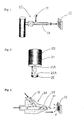
- Fig. 1 shows an apparatus of the first embodiment of this invention.
- This apparatus 10 for projecting the projectiles can project a metal ball 11 having a diameter of 4 mm on the surface of the metal product 12 through the nozzle 13 with compressed gas at a high speed.
- Table 1 shows the working conditions for projecting the projectiles and the results of the treatment.
- This treatment increases the strength of the portion of the surface since the process is instantaneously completed. Namely, nanocrystals can be formed because the small area of the surface of the metal product 12, which is projected upon by the ball 11, is quickly processed.
- the growth of the grain size in the area having nanocrystals is very slow.
- the area having nanocrystals is clearly distinguished from the other areas hardened by ordinary working or made from base materials, based on the change of the state of the micro-structure of the surface or its hardness by heating them.
- Fig. 2 shows an apparatus of the second embodiment of this invention.
- This apparatus 20 for dropping a weight can freely drop a weight 21 made of metal on the surface of the metal product 22 and cause a collision between the surface of the metal product 22 and the weight 21, to treat its surface.
- Table 1 shows the working conditions for dropping the weight and the results of the treatment.
- the metal product 22 to be treated to form nanocrystals on the surface 22A is located in the bottom of the cylinder (not shown in the Figs.).
- the metal product 22 is already machined so that it has a final configuration and cannot move in the cylinder since the configuration of the outside of the metal product closely corresponds to that of the inside of the cylinder (not shown).
- the metal weight 21 is placed at the upper part in the cylinder.
- a protrusion 21A is disposed at the surface of the metal weight 21, and the protrusion has a predetermined height (3 mm) from the surface of the weight 21.
- the protrusion 21A is disposed at the location on the weight that is opposite the point where nanocrystals should be formed on the surface 22A of the metal product 22.
- the force which is defined as a temporal response to the kinetic momentum, acts on the portion of the metal product 22 with which the protrusion 21A collides. Since the collision is completed in a short time, the strength of the portion of the metal product with which the protrusion collides increases significantly.
- the power per unit of area that is, the power per depressed area produced by the protrusion or the contact area of it, should be at least 11 KJ/sec * mm 2 .
- the accumlated kinetic momentum of the metal weight is not important, but the power per depressed area is important.
- the power per depressed area is less than 11 KJ/sec * mm 2
- no nanocrystal is formed at the surface 22A of the metal product 22. Namely, when the protrusion 21A collides with the surface 22A of the metal product 22 with a power per depressed area of more than 11 KJ/sec * mm 2 , a nanocrystal is formed at the portion with which the protrusion 21A collides.
- the protrusion be a hemispherical protrusion that projects at a height (h) of 1-10 mm from the surface of the metal weight 21.
- the protrusion may have a shape of an ellipse. If a plurality of the portions on the surface of the metal product to be treated to form nanocrystals are required, the plurality of the protrusions 21A opposite the portions may be disposed at the surface of the metal weight.
- the kinetic momentum explained above is defined as a function of the mass (M) of the metal weight 21 and the speed (V) of it at the moment that the protrusion collides.
- the mass (M) of the metal weight 21 is set between 0.1-10 Kg, and the speed of the weight at the moment that the protrusion collides is set at more than 1 m/sec, the power per depressed area of more than 11 KJ/sec * mm 2 is achieved, and the nanocrystals can be formed at the surface of the metal product.
- the metal weight 21 having the plurality of the protrusions 21A When the metal weight 21 having the plurality of the protrusions 21A is used, it is necessary to set the weight colliding with the surface 22A of the metal product 22 to the value that equals the product of the number of protrusions times the mass of the weight having a protrusion (between 0.1-10 Kg). Then, the process is completed by dropping the weight at a speed of more than 1 m/sec. Since the value of the kinetic momentum divided by the total depressed area caused by all the protrusions 21A and the deformation period satisfies the power per depressed area of more than 11 KJ/sec * mm 2 , the nanocrystals can be formed at the portions of the surface of the metal product.
- Fig. 3 shows an apparatus of the third embodiment of this invention.
- This shot-peening apparatus 30 can project shots 31 having a diameter of 50 ⁇ m, which shots 31 are made from steel, on the surface of the metal product 32 with compressed air through a nozzle 33.
- Table 1 shows the working conditions of the shot peening and the results of the treatment. From Table 1, it is found that the power per unit of area of the third embodiment to produce nanocrystals is larger than that of the first and the second embodiments.
- the pressure of the compressed air is controlled so that the projecting speed of the shots 31 at the metal product becomes 150-200 m/sec. If it is required that the entire area of the surface of the metal product be treated by shot peening, it can be treated by moving the metal product 32 so that the shots are projected over the entire area. A layer constituted of a fine crystal having grain sizes of less than 100 nm is formed at the surface of the metal product 32 by means of this shot peening process. It is found that the hardness of the layer having the fine crystal is significantly increased.
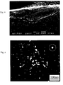
- Fig. 4 shows a photomicrograph of the surface of the metal product that is treated by the method of the third embodiment of this invention.
- Fig. 5 also shows a photomicrograph of the crystal grain that is fined by the method of the third embodiment of this invention.
- the layer constituted of a fine crystal can be formed at the surface of the metal product 32 by using the method of the third embodiment of this invention, its hardness significantly increases.
- the strength of the metal product 32 also increases, and the fatigue strength and corrosion resistance of the metal product can be improved.
- Fig. 3 shows an apparatus of the fourth embodiment of this invention, which figure is the same figure as that shown for the third embodiment.
- This shot-peening apparatus 30 can project shots 31 having a diameter of 50-300 ⁇ m and made from stainless steel on the surface of the metal product 32 with compressed air through a nozzle 33.
- Table 1 shows the working conditions of the shot peening and the results of the treatment. From Table 1, it is found that the power per unit of area of this embodiment to produce nanocrystals is larger than that of the first and the second embodiments.
- the pressure of the compressed air is controlled so that the projecting speed of the shots 31 on the metal product becomes 80 m/sec. If it is required that the entire area of the surface of the metal product be treated by the shot peening, it can be treated by moving the metal product 32 so that the shots are projected at the entire area.
- a layer constituted of a fine crystal having grain sizes of less than 100 nm is formed at the surface of the metal product 32 by means of this shot peening process. It is found that the hardness of the layer having the fine crystal is significantly increased. Shots made not only from stainless steel, but also from high-carbon steel or ferrous metallic glass, can be used. Further, shots having a range of diameters of 30 ⁇ m to 2000 ⁇ m can be used.
- a layer constituted of a fine crystal can be formed at the surface of the metal product 32 by using the method of the fourth embodiment of this invention, its hardness significantly increases.
- the strength of the metal product 32 also increases, and the fatigue strength and corrosion resistance of the metal product can be improved.
- a work hardening is caused at the surface. It is well known that the degree of the work hardening of the metal is proportional to the square root of its dislocation density.
- the rate of the work hardening decreases gradually as the degree of working increases.
- the dislocation density of the grains increases. Then, when the dislocation density reaches a critical value, a dislocation-cell structure changes to a grain-boundary structure.
- the fining of the micro-structure of the surface of the metal product is improved by projecting the projectiles or the shots to the surface while the temperature of the metal surface is controlled to be between room temperature and -150 °C. It is difficult for the number of the dislocations of the grains to reach the critical dislocation density. This allows the grains to be recrystallized, since the recovery rate of the dislocations of the grains increases with the increased temperature of the surface due to the continuius projection of the projectiles or the shots. However, in the condition at low temperature, since the recovery rate of the grain structure which is fined by projecting the projectiles or the shots decreases, it becomes easy for the number of the dislocations of the grain to increase. Namely, it become easy for the dislocation density to reach the critical value, which value allows the grain to be fined.
- liquid nitrogen temperature: -196 °C
- liquid carbon dioxide temperature: -79 °C
- This invention relates to a method for fining a surface of a metal product to form crystal grains having sizes less than 1 ⁇ m at its surface and to produce the metal product by the method.
Landscapes
- Chemical & Material Sciences (AREA)
- Engineering & Computer Science (AREA)
- Crystallography & Structural Chemistry (AREA)
- Mechanical Engineering (AREA)
- Materials Engineering (AREA)
- Metallurgy (AREA)
- Organic Chemistry (AREA)
- Other Surface Treatments For Metallic Materials (AREA)
Applications Claiming Priority (5)
| Application Number | Priority Date | Filing Date | Title |
|---|---|---|---|
| JP2002374610 | 2002-12-25 | ||
| JP2002374610 | 2002-12-25 | ||
| JP2003421143 | 2003-12-18 | ||
| JP2003421143 | 2003-12-18 | ||
| PCT/JP2003/016669 WO2004059015A1 (ja) | 2002-12-25 | 2003-12-25 | 金属表面の微細化方法及びその金属製品 |
Publications (2)
| Publication Number | Publication Date |
|---|---|
| EP1577402A1 true EP1577402A1 (de) | 2005-09-21 |
| EP1577402A4 EP1577402A4 (de) | 2006-07-05 |
Family
ID=32684234
Family Applications (1)
| Application Number | Title | Priority Date | Filing Date |
|---|---|---|---|
| EP03768204A Ceased EP1577402A4 (de) | 2002-12-25 | 2003-12-25 | Verfahren zur verfeinerung von metallflächen und durch das verfahren erzeugtes metallprodukt |
Country Status (6)
| Country | Link |
|---|---|
| US (1) | US20060289090A1 (de) |
| EP (1) | EP1577402A4 (de) |
| JP (1) | JPWO2004059015A1 (de) |
| CN (1) | CN100560750C (de) |
| AU (1) | AU2003292784A1 (de) |
| WO (1) | WO2004059015A1 (de) |
Cited By (1)
| Publication number | Priority date | Publication date | Assignee | Title |
|---|---|---|---|---|
| DE102006008170A1 (de) * | 2006-02-22 | 2007-08-23 | Halberg-Guss Gmbh | Verfahren zur Behandlung von Gussteilen |
Families Citing this family (10)
| Publication number | Priority date | Publication date | Assignee | Title |
|---|---|---|---|---|
| JP2008069938A (ja) * | 2006-09-15 | 2008-03-27 | Hino Motors Ltd | 歯車及び噛合アッセンブリ |
| CN102560045B (zh) * | 2010-12-22 | 2014-10-01 | 中国科学院金属研究所 | 块体纳米结构低碳钢及其制备方法 |
| FR2970006B1 (fr) * | 2010-12-30 | 2013-07-05 | Wheelabrator Allevard | Traitement de surface d'une piece metallique |
| WO2014025059A1 (ja) * | 2012-08-10 | 2014-02-13 | 新日鐵住金株式会社 | チタン合金材 |
| NL1041641B1 (en) * | 2015-12-22 | 2017-07-03 | Bosch Gmbh Robert | Transverse element provided with a nanocrystalline surface layer for a drive belt for a continuously variable transmission and method for producing it. |
| CN106370383B (zh) * | 2016-11-29 | 2018-11-27 | 浙江工业大学 | 多级加速喷丸装置 |
| JP7015468B2 (ja) * | 2018-01-12 | 2022-02-03 | 富士電機株式会社 | 蒸気タービン翼及びその製造方法 |
| CN113106221A (zh) * | 2021-03-23 | 2021-07-13 | 北京理工大学 | 一种金属表层低温机械强化方法及装置 |
| JP7790070B2 (ja) * | 2021-10-05 | 2025-12-23 | 新東工業株式会社 | 残留応力が付与された金属部材の製造方法 |
| CN117840923A (zh) * | 2024-01-26 | 2024-04-09 | 中国科学院理化技术研究所 | 对置式深冷喷丸装置 |
Family Cites Families (11)
| Publication number | Priority date | Publication date | Assignee | Title |
|---|---|---|---|---|
| JPS5858226A (ja) * | 1981-09-30 | 1983-04-06 | Nippon Steel Corp | 方向性電磁鋼板の鉄損低減装置 |
| JPH01240615A (ja) * | 1988-03-18 | 1989-09-26 | Nissan Motor Co Ltd | ショットピーニング方法 |
| US5205145A (en) * | 1989-09-25 | 1993-04-27 | Kubota Corporation | Method of producing torque sensor shafts |
| JPH0578798A (ja) * | 1991-09-24 | 1993-03-30 | Mazda Motor Corp | アルミニウム合金製部材の表面改質方法 |
| JPH081514A (ja) * | 1994-06-16 | 1996-01-09 | Toshiba Corp | 原子炉内構造物の表面処理方法 |
| JP2000094330A (ja) * | 1998-09-21 | 2000-04-04 | Sintokogio Ltd | ショットピーニング強さ検出装置 |
| CN1099467C (zh) * | 1999-12-24 | 2003-01-22 | 中国科学院金属研究所 | 一种金属材料表面纳米层的制备方法 |
| FR2812285B1 (fr) * | 2000-07-28 | 2003-02-07 | Univ Troyes Technologie | Procede de traitement de nanostructures et dispositif de traitement de nanostructures |
| FR2812284B1 (fr) * | 2000-07-28 | 2003-03-07 | Univ Troyes Technologie | Procede de mecanique de generation de nanostructures et dispositif mecanique de generation de nanostructures |
| EP1307599B1 (de) * | 2000-07-28 | 2004-04-21 | Universite de Technologie de Troyes | Mechanisches verfahren und vorrichtung zum erzeugen von nanostrukturen |
| JP2002036115A (ja) * | 2000-07-31 | 2002-02-05 | Sintokogio Ltd | ショットピ−ニング処理方法及びその被処理品 |
-
2003
- 2003-12-25 AU AU2003292784A patent/AU2003292784A1/en not_active Abandoned
- 2003-12-25 CN CNB2003801077551A patent/CN100560750C/zh not_active Expired - Lifetime
- 2003-12-25 EP EP03768204A patent/EP1577402A4/de not_active Ceased
- 2003-12-25 JP JP2004562930A patent/JPWO2004059015A1/ja active Pending
- 2003-12-25 WO PCT/JP2003/016669 patent/WO2004059015A1/ja not_active Ceased
- 2003-12-25 US US10/540,534 patent/US20060289090A1/en not_active Abandoned
Cited By (2)
| Publication number | Priority date | Publication date | Assignee | Title |
|---|---|---|---|---|
| DE102006008170A1 (de) * | 2006-02-22 | 2007-08-23 | Halberg-Guss Gmbh | Verfahren zur Behandlung von Gussteilen |
| DE102006008170B4 (de) * | 2006-02-22 | 2015-12-03 | Halberg-Guss Gmbh | Verfahren zur Behandlung von Gussteilen |
Also Published As
| Publication number | Publication date |
|---|---|
| CN100560750C (zh) | 2009-11-18 |
| EP1577402A4 (de) | 2006-07-05 |
| WO2004059015A1 (ja) | 2004-07-15 |
| US20060289090A1 (en) | 2006-12-28 |
| AU2003292784A1 (en) | 2004-07-22 |
| JPWO2004059015A1 (ja) | 2006-04-27 |
| CN1732274A (zh) | 2006-02-08 |
Similar Documents
| Publication | Publication Date | Title |
|---|---|---|
| US5816088A (en) | Surface treatment method for a steel workpiece using high speed shot peening | |
| EP0962539A1 (de) | Verfahren zur Oberflächenbehandlung eines metallischen Produktes | |
| US20060289090A1 (en) | Method of refining metal surface and metal product by method | |
| Azhari et al. | A review on the application of peening processes for surface treatment | |
| Peters et al. | Role of foreign-object damage on thresholds for high-cycle fatigue in Ti-6Al-4V | |
| US20100024218A1 (en) | Method of making bearing using ultrasonic nano crystal surface modification technology | |
| US3705511A (en) | Low penetration ball forming process | |
| MXPA05003309A (es) | Un aparato y metodo para mejorar la superficie de trabajo durante la formacion y conformacion de materiales. | |
| JP2014519557A (ja) | 金属部品の表面処理 | |
| JPH1029160A (ja) | 高硬度金属製品のショットピ−ニング方法及び高硬度金属製品 | |
| KR101843606B1 (ko) | 경사진 숏 피닝에 의한 금속부분 표면 처리 방법 | |
| JP6307109B2 (ja) | 金属成品の表面処理方法及び金属成品 | |
| Al-Hassani | The shot peening of metals—mechanics and structures | |
| US9115417B2 (en) | Liquid drop peening method and apparatus therefor | |
| JP2004124227A (ja) | 金属製品の表面硬化方法 | |
| JP2002530201A (ja) | 材料本体を変形するための方法および装置 | |
| JPH0457672A (ja) | ショットピーニング方法及び装置 | |
| JP2005248259A (ja) | 高強度薄鋼板及びその製造方法 | |
| Levy | The effects of the microstructure of ductile alloys on solid particle erosion behavior | |
| JP2003039398A (ja) | 金属製品表面のナノ結晶化方法 | |
| JPH10100069A (ja) | ショットピ−ニング方法及び処理物品 | |
| KR100989596B1 (ko) | 초음파 나노 개질기술을 적용한 스테인리스강(sts) 냉연와이퍼 롤 | |
| JP2004181535A (ja) | ショットピーニング方法 | |
| JPH02185369A (ja) | ショットピーニング法 | |
| Chavhan et al. | Shot peening process |
Legal Events
| Date | Code | Title | Description |
|---|---|---|---|
| PUAI | Public reference made under article 153(3) epc to a published international application that has entered the european phase |
Free format text: ORIGINAL CODE: 0009012 |
|
| 17P | Request for examination filed |
Effective date: 20050616 |
|
| AK | Designated contracting states |
Kind code of ref document: A1 Designated state(s): AT BE BG CH CY CZ DE DK EE ES FI FR GB GR HU IE IT LI LU MC NL PT RO SE SI SK TR |
|
| AX | Request for extension of the european patent |
Extension state: AL LT LV MK |
|
| DAX | Request for extension of the european patent (deleted) | ||
| A4 | Supplementary search report drawn up and despatched |
Effective date: 20060608 |
|
| 17Q | First examination report despatched |
Effective date: 20100201 |
|
| STAA | Information on the status of an ep patent application or granted ep patent |
Free format text: STATUS: THE APPLICATION HAS BEEN REFUSED |
|
| 18R | Application refused |
Effective date: 20101027 |