EP1575189B1 - Système et méthode de communication par satellites capable d'effectuer des activations de porteuses avec garantie de fiabilité du chemin de communication - Google Patents
Système et méthode de communication par satellites capable d'effectuer des activations de porteuses avec garantie de fiabilité du chemin de communication Download PDFInfo
- Publication number
- EP1575189B1 EP1575189B1 EP05013354A EP05013354A EP1575189B1 EP 1575189 B1 EP1575189 B1 EP 1575189B1 EP 05013354 A EP05013354 A EP 05013354A EP 05013354 A EP05013354 A EP 05013354A EP 1575189 B1 EP1575189 B1 EP 1575189B1
- Authority
- EP
- European Patent Office
- Prior art keywords
- signal
- mobile
- antenna
- carrier signal
- burst
- Prior art date
- Legal status (The legal status is an assumption and is not a legal conclusion. Google has not performed a legal analysis and makes no representation as to the accuracy of the status listed.)
- Expired - Lifetime
Links
Images


Classifications
-
- H—ELECTRICITY
- H04—ELECTRIC COMMUNICATION TECHNIQUE
- H04B—TRANSMISSION
- H04B7/00—Radio transmission systems, i.e. using radiation field
- H04B7/14—Relay systems
- H04B7/15—Active relay systems
- H04B7/185—Space-based or airborne stations; Stations for satellite systems
- H04B7/1853—Satellite systems for providing telephony service to a mobile station, i.e. mobile satellite service
- H04B7/18532—Arrangements for managing transmission, i.e. for transporting data or a signalling message
-
- H—ELECTRICITY
- H04—ELECTRIC COMMUNICATION TECHNIQUE
- H04B—TRANSMISSION
- H04B7/00—Radio transmission systems, i.e. using radiation field
- H04B7/14—Relay systems
- H04B7/15—Active relay systems
- H04B7/204—Multiple access
- H04B7/208—Frequency-division multiple access [FDMA]
Definitions
- This invention relates to a mobile satellite communication method and a mobile satellite communications system for carrying out communications via a communications satellite between an earth station and a mobile station with an automatic tracking type antenna.
- multiplex techniques called multiple accesses are used in order to effectively utilize assigned frequencies and to decrease transmission power up to now.
- a frequency division multiple access (FDMA) system which assigns frequencies for a satellite transponder, is widely used in the satellite communications system presently. This is because the FDMA system can apply techniques established in a ground communication, has a low initial cost, and can be relatively easily realized.
- FDMA frequency division multiple access
- the FDMA system is disadvantageous in that throughput drastically decrease when the number of channel connections increases. More specifically, when the number of channel connections increases, transmission power in the satellite transponder increases and an amplifier in the transponder may operate at an operating point near to a saturation point thereof. Therefore, intermodulation accompanied with waveform distortion occurs and interference between channels occurs. As a result, quality of a communication path decreases, it is difficult to use the communication path, and throughput drastically decreases. Accordingly, in the satellite communications system of the FDMA system, use is made of carrier activation in order to avoid these problems.
- carrier activation is described by G. Maral, et al. in a book under the title of "SATELLITE COMMUNICATIONS SYSTEM 2nd Edition", John Wiley & Sons, Inc. 1993 or is described by Vijay K. Bhargava, et al. in a book under the title of "DIGITAL COMMUNICATIONS BY SATELLITE", John Wiley & Sons, Inc. 1981 .
- voice activation is carried out which detects a speech and transmits a carrier signal during a time duration when the speech is detected in a telephone call.
- voice activation inasmuch as the carrier signal is not transmitted during a pause time duration in the telephone call when the voice is not detected, it is possible to decrease an average transmission power in the satellite and to ensure a channel capacity with intermodulation prevented.
- Figs. 6A and 6B are time charts for showing signals in a case of carrying out the voice activation.
- Fig. 6A shows a speech signal while
- Fig. 6B shows a transmission signal.
- sending of the transmission signal is basically stopped.
- Such carrier activation is applied not only to a case of transmitting a speech signal but also to a case of transmitting a data signal for use in a facsimile equipment or a computer and transmission of the carrier signal is stopped when the data signal to be transmitted is not supplied.
- a burst carrier signal 102 is periodically transmitted at predetermined time intervals in order to maintain a channel connection state between an earth station and a mobile station when the time duration of a transmission stop is not less than a predetermined time duration with no information signal (no speech signal or no data signal to be transmitted) supplied.
- a burst carrier signal is call a maintaining burst signal.
- the mobile station when the mobile station uses an automatic tracking type antenna as a mobile antenna, the mobile station normally receives a signal from the satellite and carries out a tracking control on the basis of a level of the received signal so as to turn a direction of the mobile antenna toward the satellite. Accordingly, such a mobile station must carry out the tracking control using only the maintaining burst signal during a time duration when the carrier signal from the earth station is interrupted due to the carrier activation. It is difficult to control accurately when a bad condition is piled up.
- the received signal may not be received stably due to a shadowing which occurs because variation of a transmission condition peculiar to a mobile satellite communication. It is increasingly difficult to carry out the tracking control in such a state.
- a mobile satellite communication method to which the present invention is applicable carries out communications via a communications satellite between an earth station and a mobile station with an automatic tracking type antenna.
- the earth station transmits, to the mobile station, a modulated signal into which a carrier signal is modulated by an information signal supplied thereto.
- the mobile satellite communication method carries out carrier activation where the earth station periodically transmits a burst carrier signal having a burst transmission duration to the mobile station when the information signal is not supplied thereto.
- the earth station extends the burst transmission duration for the burst carrier signal when the earth station receives, from the mobile station, a carrier signal having a carrier frequency which varies with variation exceeding a reference value.
- a mobile satellite communications system to which the present invention is applicable carries out communications via a communications satellite between an earth station and a mobile station with an automatic tracking type antenna.
- the earth station transmits, to the mobile station, a modulated signal into which a carrier signal is modulated by an information signal supplied thereto.
- the mobile satellite communications system carries out carrier activation where the earth station periodically transmits a burst carrier signal having a burst transmission duration to the mobile station when the information signal is not supplied thereto.
- the earth station comprises a carrier frequency variation detecting arrangement for detecting variation in a carrier frequency of a received carrier signal and a carrier signal controlling arrangement for carrying out control of a carrier transmission for a signal to be transmitted to the mobile station.
- the carrier frequency variation detecting arrangement When the carrier frequency of the received carrier signal varies with variation exceeding a reference value, the carrier frequency variation detecting arrangement produces a carrier frequency variation detected signal. Responsive to the carrier frequency variation detected signal, the carrier signal controlling arrangement extends the burst transmission duration for the burst carrier signal.
- this invention extends the burst transmission duration for the burst carrier signal or a maintaining burst signal when the carrier frequency of the received carrier signal varies with the variation exceeding the reference value. Accordingly, the mobile station can easily carry out an automatic tracking control for the automatic tracking type antenna and can easily maintain a frame synchronization or can easily establish the frame synchronization although the frame synchronization is pulled out. As a result, it is possible to carry out the tracking control stably and to maintain the frame synchronization stably. That is, it is possible to carry out carrier activation with channel quality having high reliability secured.
- a mobile satellite communication method to which the present invention is applicable carries out communications via a communications satellite between an earth station and a mobile station with an automatic tracking type antenna.
- the earth station transmits, to the mobile station, a modulated signal into which a carrier signal is modulated by an information signal supplied thereto.
- the earth station periodically transmits a burst carrier signal having a burst transmission duration to the mobile station when the information signal is not supplied thereto.
- the earth station receives a received signal from the mobile station.
- the earth station continuously transmits the carrier signal when the earth station cannot establish a frame synchronization for the received signal.
- a mobile satellite communications system to which the present invention is applicable carries out communications via a communications satellite between an earth station and a mobile station with an automatic tracking type antenna.
- the earth station transmits, to the mobile station, a modulated signal into which a carrier signal is modulated by an information signal supplied thereto.
- the mobile satellite communications system carries out carrier activation where the earth station periodically transmits a burst carrier signal having a burst transmission duration to the mobile station when the information signal is not supplied thereto.
- the earth station comprises a receiver for receiving a received signal from the mobile station.
- the earth station comprises a carrier signal controlling arrangement for carrying out a carrier transmission control for a signal to be transmitted to the mobile station and a frame synchronizing arrangement for establishing a frame synchronization for the received signal to produce a frame synchronization signal.
- the carrier signal controlling arrangement continuously transmits the carrier signal to the mobile station.
- the earth station continuously transmits the carrier signal without transmitting the burst carrier signal when the earth station cannot establish the frame synchronization for the received signal. Accordingly, the mobile station can easily carry out an automatic tracking control for the automatic tracking type antenna and can easily maintain the frame synchronization or can easily establish the frame synchronization although the frame synchronization is pulled out. As a result, it is possible to carry out the tracking control stably and to maintain the frame synchronization. That is, it is possible to carry out carrier activation with channel quality having high reliability secured.
- a mobile satellite communication method to which the present invention is applicable carries out communications via a communications satellite between an earth station and a mobile station with an automatic tracking type antenna.
- the earth station transmits, to the mobile station, a modulated signal into which a carrier signal is modulated by an information signal supplied thereto.
- the mobile satellite communication method carries out carrier activation where the earth station periodically transmits a burst carrier signal having a burst transmission duration to the mobile station when the information signal is not supplied thereto.
- the earth station extends the burst transmission duration of the burst carrier signal when a received signal from the mobile station has a received level which varies with variation exceeding threshold.
- a mobile satellite communications system to which the present invention is applicable comprises an earth station, a mobile station with an automatic tracking type antenna, and a communications satellite for mediating communications between the earth station and the mobile station.
- the earth station comprises a carrier signal controlling arrangement for transmitting, to the mobile station, a modulated signal into which a carrier signal is modulated by an information signal supplied thereto and for periodically transmitting a burst carrier signal having a burst transmission duration to the mobile station when the information signal is not supplied thereto.
- the earth station comprises a level monitoring arrangement for producing a level variation detected signal when a received signal from the mobile station has a received level which varies with variation exceeding a threshold. Responsive to the level variation detected signal, the carrier signal controlling arrangement extends the burst transmission duration for the burst carrier signal.
- the earth station extends the burst transmission duration for the burst carrier signal when the received level of the received signal varies with the variation exceeding the threshold. Accordingly, the mobile station can easily carry out an automatic tracking control for the automatic tracking type antenna and can easily establish a frame synchronization. As a result, it is possible to carry out the tracking control stably, to establish the frame synchronization stably, and to maintain a channel quality with high level. That is, it is possible to carry out carrier activation with reliability of a transmission path secured.
- a mobile satellite communication method to which the present invention is applicable carries out communications via a communications satellite between an earth station and a mobile station with a mobile antenna.
- the earth station transmits, to the mobile station, a modulated signal into which a carrier signal is modulated by an information signal supplied thereto.
- the earth station periodically transmits a burst carrier signal having a burst transmission duration to the mobile station when the information signal is not supplied thereto.
- the mobile station transmits, to the earth station, a predetermined signal indicating whether or not the mobile antenna is an automatic tracking type antenna to give the earth station notice of the predetermined signal.
- the earth station extends the burst transmission duration for the burst carrier signal when the earth station receives the predetermined signal indicating that the mobile station is the automatic tracking type antenna.
- a mobile satellite communications system to which the present invention is applicable comprises an earth station, a mobile station with a mobile antenna, and a communications satellite for mediating communications between the earth station and the mobile station.
- the earth station comprises a carrier signal controlling arrangement for transmitting, to the mobile station, a modulated signal into which a carrier signal is modulated by an information signal supplied thereto and for periodically transmitting a burst carrier signal having a burst transmission duration to the mobile station when the information signal is not supplied thereto.
- the mobile station comprises an antenna type notification arrangement for transmitting, to the earth station, an antenna type notification signal indicating whether or not the mobile antenna is an automatic tracking type antenna.
- the carrier signal controlling arrangement extends the burst transmission duration for the burst carrier signal on reception of the antenna type notification signal indicating that the mobile antenna is the automatic tracking type antenna.
- the mobile station gives the earth station notice whether or not the mobile antenna is the automatic tracking type antenna.
- the earth station extends the burst transmission duration for the burst carrier signal when the earth station receives notice that the mobile antenna is the automatic tracking type antenna. Accordingly, the mobile station can easily carry out an automatic tracking control for the mobile antenna and can easily establish a frame synchronization. As a result, it is possible to carry out the tracking control stably, to establish the frame synchronization in stable, and to maintain a channel quality with high level. That is, it is possible to carry out carrier activation with reliability of a transmission path secured.
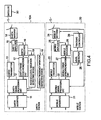
- the illustrated mobile satellite communications system comprises an earth station 10, a mobile station 20, and a communications satellite (herein merely called a satellite) 30 for mediating communications between the earth station 10 and the mobile station 20.
- a communications satellite herein merely called a satellite
- the earth station 10 comprises an earth interface 11, an earth signal processing circuit 12, an earth transmitter 13, an earth antenna 14, an earth duplexer 15, an earth receiver 16, an earth frame synchronization circuit 17, and a carrier frequency variation detecting device 18.
- the mobile station 20 comprises a mobile interface 21, a mobile signal processing circuit 22, a mobile transmitter 23, a mobile antenna 24, a mobile duplexer 25, a mobile receiver 26, a mobile frame synchronization circuit 27, a level detector 28, and a tracking controller 29.
- the earth interface 11 is connected to a general network (not shown) and a leased circuit (not shown) (which are also hereinafter collectively called a ground circuit).
- the earth interface 11 carries out a protocol control for transmitting and receiving an information signal to and from the ground circuit.
- the information signal is transmitted to and received from the mobile station 20.
- the information signal may be a speech signal or a data signal.
- the earth interface 11 converts an analog signal supplied from the ground circuit into a digital signal and converts a digital signal received from the mobile station 20 into an analog signal.
- the earth interface 11 encodes a signal inputted from an external and decodes a received signal from the mobile station 20.
- the earth signal processing circuit 12 transmits a line control signal to the earth interface 11 and multiplexes a signal from the earth interface 11 into a multiplexed signal having a data format for transmitting via a satellite communication path.
- the earth signal processing circuit 12 serves as a signal processing arrangement according to this invention. That is, the earth signal processing circuit 12 separates a multiplexed signal received at the data format of the satellite communication path to extract an information signal. Furthermore, when the line control signal is included in the multiplexed signal, the earth signal processing circuit 12 analyzes the line control signal.
- a combination of the earth signal processing circuit 12 and the earth transmitter 13 acts as a carrier signal controlling arrangement according to this invention.
- the carrier signal controlling arrangement processes the information signal inputted via the earth interface 11 from the ground circuit in the manner which is described above, modulates the carrier signal to supply a modulated signal to the earth antenna 14 via the earth duplexer 15 and transmits the modulated signal to the mobile station 20.
- the carrier signal controlling arrangement carries out carrier activation by controlling the earth transmitter 13 by the earth signal processing circuit 12 to periodically transmit a burst carrier signal having a burst transmission duration to the mobile station 20.
- the carrier signal controlling arrangement extends the burst transmission duration for the burst carrier signal.
- the carrier signal controlling arrangement continuously transmits the carrier signal when a predetermined time duration elapses while the earth frame synchronization circuit 17 does not produce a synchronization establishment signal.
- the carrier signal controlling arrangement extends the burst transmission duration for the burst carrier signal when the carrier signal controlling arrangement receives, from the mobile station 20, an antenna type notification signal indicating that the mobile antenna 24 is an automatic tracking type antenna.
- the earth duplexer 15 permits alternate use of the earth antenna 14 for both transmitting and receiving. That is, the earth duplexer 15 supplies a signal from the earth transmitter 13 to the earth antenna 14 and supplies a signal from the earth antenna 14 to the earth receiver 16. In addition, the earth antenna 14 is set up so as to turn a principal surface of the earth antenna 14 toward the satellite 30. The earth antenna 14 transmits and receives an electric wave to and from the satellite 30.
- the earth receiver 16 amplifies a received signal from the earth antenna 14 via the earth duplexer 15.
- the earth receiver 16 separates the frequency multiplexed signal into a plurality of separated signals and selects, as a selected signal, one of the separated signals.
- the earth receiver 16 converts the selected signal into an intermediate signal having an intermediate frequency.
- the earth receiver 16 includes a demodulating section (not shown) for demodulating the intermediate signal to regenerate, as a regenerated signal, a signal which the mobile station 20 transmits.
- the earth frame synchronization circuit 17 receives the regenerated signal from the earth receiver 16 and detects a unique word in the regenerated signal to establish a frame synchronization.
- the earth frame synchronization circuit 17 generates a frame synchronization signal serving as a time base for signal processing in the earth signal processing circuit 12.
- the earth frame synchronization circuit 17 acts as a synchronization monitoring arrangement for supplying the earth signal processing circuit 12 with the synchronization establishment signal when the frame synchronization is established.
- the carrier frequency variation detecting device 18 takes out a carrier frequency information signal (a received carrier signal) having a received carrier frequency from the demodulating section composing a part of the earth receiver 16 to detect a frequency variation in the received carrier signal.
- a carrier frequency information signal (a received carrier signal) having a received carrier frequency from the demodulating section composing a part of the earth receiver 16 to detect a frequency variation in the received carrier signal.
- the complex multiplier 41 is supplied with the received carrier signal from the earth receiver 16. In addition, the complex multiplier 41 is supplied with a regenerated carrier signal from the voltage controlled oscillator 44 in the manner which will become clear as the description proceeds.
- the complex multiplier 41 complex multiplies the received carrier signal by the regenerated carrier signal to produce a multiplied result signal.
- the multiplied result signal is supplied to the phase' detector 42.
- the phase detector 42 detects a phase error (a phase difference) between the regenerated carrier signal and the received carrier signal on the basis of the multiplied result signal.
- the phase detector 42 produces a phase error signal indicative of the phase error.
- the phase error signal is supplied to the loop filter 43.
- the loop filter 43 removes a high frequency component from the phase error signal to produce a control voltage.
- the control voltage is supplied to the voltage controlled oscillator 44. Responsive to the control voltage, the voltage controlled oscillator 44 generates the regenerated carrier signal having a controllable oscillation frequency.
- the differentiating circuit 45 differentiates the control voltage to produce a differential voltage.
- the differentiating circuit 45 is connected to the frequency variation detector 46.
- the frequency variation detector 46 is supplied with a threshold voltage V th . When the differential voltage exceeds the threshold voltage V th , the frequency variation detector 46 produces a pulse which is supplied to the earth signal processing circuit 12 as the frequency variation detected signal.
- phase locked loop 40 catches the received carrier signal and makes the regenerated carrier signal follow so as to synchronize a carrier phase of the received carrier signal. Accordingly, when variation occurs in the received carrier frequency of the received carrier signal due to a doppler effect or a frequency drift of a local oscillator for generating a carrier signal in the satellite transponder or the mobile station 20, a phase shift between the received carrier signal and the regenerated carrier signal occurs and it is observed as the phase error.
- the control voltage corresponding to the phase error is supplied to the voltage controlled oscillator 44 to control the controllable oscillation frequency of the regenerated carrier signal.
- information indicative of the received carrier frequency of the received carrier signal appears as the control voltage of the loop filter 43 owing to following of the phase locked loop 40.
- the differentiating circuit 45 produces the differential voltage indicative of the magnitude of the variation in the received carrier frequency of the received carrier signal. And then, the frequency variation detector 46 supplies the frequency variation detected signal to the earth signal processing circuit 12 when the variation in the received carrier frequency exceeds a threshold.
- the mobile station 20 comprises the mobile interface 21, the mobile signal processing circuit 22, the mobile transmitter 23, the mobile antenna 24, the mobile duplexer 25, the mobile receiver 26, the mobile frame synchronization circuit 27, the level detector 28, and the tracking controller 29.
- the mobile interface 21, the mobile signal processing circuit 22, the mobile transmitter 23, the mobile antenna 24, the mobile duplexer 25, the mobile receiver 26, and the mobile frame synchronization circuit 27 are basically similar in structure and operation to the earth interface 11, the earth signal processing circuit 12, the earth transmitter 13, the earth antenna 14, the earth duplexer 15, the earth receiver 16, and the earth frame synchronization circuit 17, respectively.
- the mobile station 20 has no function for control of the carrier signal and differ from those in the earth station 10.
- the mobile antenna 24 is an automatic tracking type antenna.
- the mobile interface 21 is connected to a telephone set (a hand set) (not shown), a facsimile equipment (not shown), a date terminal equipment (not shown) such as a personal computer, or the like.
- a combination of the mobile signal processing circuit 22 and the mobile transmitter 23 serves as an antenna type notifying arrangement for transmitting, to the earth station 10, the antenna type notification signal indicating whether or not the mobile antenna 24 is the automatic tracking type antenna.
- the level detector 28 detects a level of a mobile received signal which is received by the mobile receiver 26.
- the level detector 28 produces a level detected signal indicative of the level of the mobile received signal.
- the level detected signal is supplied to the tracking controller 29. Responsive to the level detected signal, the tracking controller 29 controls a direction of the mobile antenna 24 so that the level of the mobile received signal has the maximum.
- the mobile signal processing circuit 22 detects the calling through the mobile interface 21 to generate a line control signal for requesting a channel connection of a satellite communication path and sends the line control signal to the mobile transmitter 23.
- the mobile transmitter 23 On reception of the line control signal, the mobile transmitter 23 carries out, on the basis of the line control signal, modulation of a carrier signal, multiplexing, and power amplification to supply a modulated signal to the mobile antenna 24 and transmits it to a network management station (not shown) .
- the network management station assigns a communication channel to the mobile station 20 and the earth station 10.
- Each of the mobile station 20 and the earth station 10 carries out a predetermined access control using the assigned communication channel.
- the mobile signal processing circuit 22 in the mobile station 20 determines a type of the mobile antenna 24 which is presently used. Inasmuch as the mobile antenna 24 is the automatic tracking type antenna, the mobile signal processing circuit 22 generates the antenna type notification signal indicating that the mobile antenna 24 is the automatic tracking type antenna and transmits it to the earth station 10 through the mobile transmitter 23.
- the earth signal processing circuit 12 receives the antenna type notification signal. Inasmuch as the antenna type notification signal indicates that the mobile antenna 24 is the automatic tracking type antenna, the earth signal processing circuit 12 sets a long burst transmission duration which is longer than that in a case of a non-tracking antenna on transmitting a burst carrier signal or a maintaining burst signal by controlling the earth transmitter 13.
- the earth station 10 transmits the maintaining burst signal having the long burst transmission duration to the mobile station 20.
- the mobile station 20 receives the maintaining burst signal having the long burst transmission duration, it is possible to easily carry out an automatic tracking control in the mobile antenna 24 by using the level detector 28 and the tracking controller 29.
- the mobile frame synchronization circuit 27 can easily establish the frame synchronization and it is possible to avoid breaking of the channel connection and to rapidly return a line state although the frame synchronization is pulled out without being enable to track. Accordingly, it is possible to carry out the carrier activation with reliability in a communication path secured.
- Fig. 3A shows a waveform of a transmission signal in the earth station 10 and Fig. 3B shows a waveform of a received signal in the earth station 10.
- Fig. 3C shows the synchronization establishment signal produced by the earth frame synchronization circuit 17 and Fig. 3D shows the received carrier frequency f of the received carrier signal produced by the earth receiver 16.
- Fig. 3E shows a waveform of the differential signal df/dt produced by the differentiating circuit 45 and Fig. 3F shows the frequency variation detected signal produced by the frequency variation detector 46.
- a speech signal is supplied to the earth interface 11 via the ground circuit up to a time instant t1.
- the speech signal is multiplexed with other signals by the earth signal processing circuit 12, is power amplified by the earth transmitter 13, and is transmitted to the mobile station 20 via the satellite 30 from the earth antenna 14.
- the earth receiver 16 receives an earth received signal 52 modulated by a speech signal through the earth antenna 14 to regenerate, as a regenerated signal, a signal which the mobile station 20 transmits.
- the earth frame synchronization circuit 17 establishes the frame synchronization by detecting the unique word in the regenerated signal to produce the frame synchronization signal used as the time base for signal processing in the earth signal processing circuit 12 and to supply it to the earth signal processing circuit 12.
- the earth frame synchronization circuit 17 is operable as the synchronization monitoring arrangement. Inasmuch as the frame synchronization is established, the earth frame synchronization circuit 17 supplies the earth signal processing circuit 12 with the synchronization establishment signal having a logic high level as shown in Fig. 3B.
- the mobile station 20 changes its moving direction against the satellite 30 at a time instant t3 as shown in Figs. 3A through 3C.
- the received carrier frequency f of the received carrier signal changes due to the doppler effect as shown in Fig. 3D.
- the phase locked loop 40 (Fig. 2) follows variation of the received carrier frequency f.
- the loop filter 43 produces the control voltage which varies in response to the variation of the received carrier frequency f.
- the differentiating circuit 45 produces the differential voltage df/dt indicative of the variation of the control voltage or of the magnitude of the variation of the received carrier frequency f.
- the frequency variation detector 46 supplies the earth signal processing circuit 12 with the frequency variation detected signal when the variation of the received carrier frequency exceeds the threshold.
- the earth signal processing circuit 12 extends the burst transmission duration and transmits a maintaining burst signal 53 having the extended burst transmission duration by controlling the earth transmitter 13.
- the mobile station 20 changes its moving direction against the satellite 30 as mentioned before, it is possible for the mobile station 20 to easily carry out the automatic tracking control of the mobile antenna 24 by using the level detector 28 and the tracking controller 29. It results in the tracking control stably.
- the mobile frame synchronization circuit 27 it is possible for the mobile frame synchronization circuit 27 to achieve the frame synchronization stably. This is because the mobile frame synchronization circuit 27 can maintain the frame synchronization and can rapidly establish the frame synchronization although the frame synchronization is pulled out. As a result, it is possible to carry out the carrier activation with reliability in the communication path secured.
- variation of the received carrier frequency f remarkably occurs due to orbit movement of the satellite 30 in a case where the satellite 30 is a non-geostationary satellite. It is possible to secure the channel connection stably in such a case. This is because the burst transmission duration is extended in the similar manner.
- the earth received signal attenuates at a time instant t4 as shown in Fig. 3B because of, for example, shadowing or failure of the antenna tracking control in the mobile station 20.
- the earth frame synchronization circuit 17 cannot establish the frame synchronization and the earth frame synchronization circuit 17 acting as the synchronization monitoring arrangement stops production of the synchronization establishment signal as shown in Fig. 3C.
- the earth signal processing circuit 12 makes the earth transmitter 13 continuously transmit a carrier signal 54 by controlling the earth transmitter 13 although the speech signal is not supplied from the ground circuit.
- the earth frame synchronization circuit 17 produces the synchronization establishment signal at a time instant t6.
- the earth signal processing circuit 12 stops a continuous transmission of the carrier signal.
- the mobile station 20 transmits a maintaining burst signal in the similar manner as the earth station 10 when the mobile station 20 does not transmit the information signal, it is possible to always establish the frame synchronization if the communication path is normal. Accordingly, if the frame synchronization cannot be established it is judged that the shadowing or the failure of the antenna tracking control in the mobile station 20 occurs as mentioned before. As a result, it is effective that the earth station 10 continuously transmits the carrier signal.
- the mobile station 20 inasmuch as the carrier signal is continuously transmitted from the earth station 10 when the shadowing or the failure of the antenna tracking control in the mobile station 20 occur, it is possible for the mobile station 20 to return to a communicable state by certainly carrying out the tracking control for the mobile antenna 24 to rapidly turn a direction of the mobile antenna 24 toward the satellite 30 accurately.
- the mobile frame synchronization circuit 27 it is easy for the mobile frame synchronization circuit 27 to establish the frame synchronization. As a result, it is possible to carry out the carrier activation with reliability in the communication path secured.
- the mobile signal processing circuit 22 detects the type of the mobile antenna 24 to transmit the antenna type notification signal in the above-mentioned first embodiment, the mobile signal processing circuit 22 may preliminarily store information indicative of whether or not the mobile antenna 24 is the automatic tracking type antenna and may generate the antenna type notification signal on the basis of the information to transmit it.
- the mobile satellite communications system is similar in structure and operation to that illustrated in Fig. 1 except that the earth station is modified from that illustrated in Fig. 1 as will later become clear.
- the earth station is therefore depicted at 10A.
- the earth station 10A is similar in structure and operation to the earth station 10 illustrated in Fig. 1 except that the earth station 10A further comprises a received, level variation detecting device 19.
- components similar to those in Fig. 1 are attached with the same reference symbols and the description thereof is therefore omitted herein.
- a signal line depicted at a thick line represents a quadrature signal (a complex signal).
- the earth receiver 16 comprises a filter 161 and a demodulator 162.
- the filter 161 filters the earth received signal into a filtered signal.
- the filtered signal is supplied to the demodulator 162 and the received level variation detecting device 19.
- the demodulator 162 demodulates the filtered signal into a demodulated signal.
- the received level variation detecting device 19 comprises a power detector 191, an averaging circuit 192, a differentiating circuit 193, a level variation detector 194, a gate generating circuit 195, and an AND gate 196.
- the power detector 191 is supplied with the filtered signal from the filter 161.
- the power detector 191 detects power of the filtered signal to produce a power detected signal.
- the power detected signal is supplied to the averaging circuit 192.
- the averaging circuit 192 averages the power detected signal to produce an averaged signal indicative of an average power of the earth received signal.
- the averaged signal is supplied to the differentiating circuit 195.
- the differentiating circuit 195 differentiates the averaged signal to produce a differential signal.
- the differential signal is supplied to the level variation detector 194. On the basis of the differential signal and a predetermined threshold V th , the level variation detector 194 detects variation of a received level of the earth received signal to produce a level variation detected signal.
- the level variation detected signal is supplied to an input terminal of the AND gate 196.
- the gate generating circuit 195 is supplied with the frame synchronization signal from the earth frame synchronization circuit 17. Responsive to the frame synchronization signal, the gate generating circuit 195 generates a gate signal for detecting variation of the received level. The gate signal is supplied to another input terminal of the AND gate 196.
- the earth received signal which is transmitted from the mobile station 20 and is received in the earth station 10A, is supplied to the power detector 191 through the filter 161 in the earth receiver 16.
- the filtered signal is power detected by the power detector 191 and is averaged by the averaging circuit 192 to obtain the averaged signal indicative of the average power of the earth received signal.
- the differentiating circuit 193 differentiates the averaged signal to calculate fluctuation in the received power.
- the level variation detector 194 compares the fluctuation in the received power with the predetermined threshold V th . When the fluctuation in the received power exceeds the predetermined threshold V th , the level variation detector 194 produces the level variation detected signal which is supplied to the AND gate 196.
- the earth signal processing circuit 12 When receiving the level variation detected signal, the earth signal processing circuit 12 sets the burst transmission duration of the maintaining burst signal, which is to be transmitted when the information signal such as the speech signal is not supplied to the earth interface 11, so as to become longer than that in a case of normal.
- the burst transmission duration for the maintaining burst signal transmitted from the earth station 10A to the mobile station 20 is set so as to become longer than normal when the received level of the earth received signal in the earth station 10A attenuates because the shadowing occurs or the antenna tracking control in the mobile station 20 is not always carried out accurately, it is possible for the mobile station 20 to easily carry out the automatic tracking control in the mobile antenna 24 and it results in stable tracking control.
- the mobile frame synchronization circuit 27 it is possible for the mobile frame synchronization circuit 27 to achieve stable frame synchronization. This is because the mobile frame synchronization circuit 27 can maintain the frame synchronization and can rapidly establish the frame synchronization although the frame synchronization is pulled out.
Landscapes
- Engineering & Computer Science (AREA)
- Physics & Mathematics (AREA)
- Astronomy & Astrophysics (AREA)
- Aviation & Aerospace Engineering (AREA)
- General Physics & Mathematics (AREA)
- Computer Networks & Wireless Communication (AREA)
- Signal Processing (AREA)
- Radio Relay Systems (AREA)
- Mobile Radio Communication Systems (AREA)
Claims (14)
- Procédé permettant d'effectuer des communications par l'intermédiaire d'un satellite de communication (30) entre une station terrestre (10, 10A) et une station mobile (20) avec une antenne de poursuite automatique (24), ladite station terrestre transmettant, à ladite station mobile, un signal modulé dans lequel un signal porteur est modulé par un signal d'information qui lui est fourni, ladite station terrestre transmettant périodiquement un signal porteur en rafales à ladite station mobile lorsque le signal d'information ne lui est pas fourni, ladite station terrestre recevant un signal reçu à partir de ladite station mobile, caractérisé en ce que ledit procédé comprend l'étape consistant à :transmettre (17, 12) de façon continue, à partir de ladite station terrestre, le signal porteur à ladite station mobile lorsque ladite station terrestre ne peut pas établir une synchronisation de trames pour le signal reçu.
- Procédé selon la revendication 1, dans lequel ledit signal porteur en rafales a une durée de transmission par rafales, et ledit procédé comprend l'étape consistant à :étendre (16, 18, 12), dans ladite station terrestre, la durée de transmission par rafales du signal porteur en rafales lorsque ladite station terrestre reçoit, à partir de ladite station mobile, un signal porteur ayant une fréquence de porteuse qui varie avec une variation excédant une valeur de référence.
- Procédé selon la revendication 1, dans lequel ledit signal porteur en rafales a une durée de transmission par rafales et ledit procédé comprend l'étape consistant à :étendre (16, 19, 12), dans ladite station terrestre, la durée de transmission par rafales du signal porteur en rafales lorsque ladite station terrestre reçoit le signal reçu ayant un niveau reçu qui varie avec une variation excédant un seuil.
- Procédé selon la revendication 1, dans lequel ledit signal porteur en rafales a une' durée de transmission par rafales.et ledit procédé comprend les étapes consistant à :transmettre (22), à partir de ladite station mobile, un signal prédéterminé indiquant si une antenne mobile (24) est une antenne de poursuite automatique ou pas pour donner à ladite station terrestre une notification du signal prédéterminé ; etétendre (12), dans ladite station terrestre, la durée de transmission par rafales du signal porteur en rafales lorsque ladite station terrestre reçoit le signal prédéterminé indiquant que l'antenne mobile est l'antenne de poursuite automatique.
- Système de communication mobile par satellite comprenant une station terrestre (10), une station mobile (20) avec une antenne de poursuite automatique, et un satellite de communication (30) pour réaliser des communications entre ladite station terrestre et ladite station mobile, ladite station terrestre comprenant des moyens de commande de signal porteur (12, 13) pour transmettre, à ladite station mobile, un signal porteur avec le signal porteur modulé par un signal d'information qui lui est fourni, lesdits moyens de commande de signal porteur transmettant périodiquement un signal porteur en rafales ayant une durée de transmission par rafales à ladite station mobile lorsque le signal d'information ne lui est pas fourni, un récepteur (16) pour recevoir un signal reçu à partir de ladite station mobile, des moyens de synchronisation de trames (17) pour établir une synchronisation de trames pour le signal reçu afin de produire un signal de synchronisation de trames, et des moyens de traitement de signal (12) pour extraire un signal d'information à partir du signal reçu sur la base du signal de synchronisation de trames,
lesdits moyens de synchronisation de trames comprennent des moyens de contrôle de trames (17) pour produire un signal d'établissement de synchronisation lorsque lesdits moyens de synchronisation de trames établissent la synchronisation de trames, lesdits moyens de commande de signal porteur transmettant de façon continue le signal porteur lorsque lesdits moyens de contrôle de trames ne produisent pas le signal d'établissement de synchronisation. - Système de communication mobile par satellite selon la revendication 5, dans lequel lesdits moyens de commande de signal porteur qui transmettent de façon continue le signal porteur après qu'une durée de temps prédéterminée se soit écoulée tandis que lesdits moyens de contrôle de synchronisation arrêtent la production du signal d'établissement de synchronisation.
- Système de communication mobile par satellite selon la revendication 5, dans lequel ladite station terrestre comprend :des moyens de détection de variation de fréquence (18), connectés auxdits moyens de commande de signal porteur (12, 13) et audit récepteur (16), pour détecter que le signal porteur reçu a une fréquence de porteuse' qui varie avec une variation excédant une valeur de référence, lesdits moyens de détection de variation de fréquence produisant un signal détecté par variation de fréquence lorsque la fréquence de porteuse du signal porteur reçu varie avec la variation excédant la valeur de référence,lesdits moyens de commande de signal porteur étendant la durée de transmission par rafales du signal porteur en rafales en réponse au signal détecté par variation de fréquence.
- Système de communication mobile par satellite selon la revendication 7, dans lequel lesdits moyens de détection de variation de fréquence (18) comprennent :une boucle à verrouillage de phase (40) comprenant un oscillateur commandé en tension (44) pour faire osciller un signal de sortie ayant une fréquence d'oscillation en réponse à une tension de commande, ladite boucle à verrouillage de phase commandant la tension de commande sur la base d'une différence de phase entre le signal porteur reçu et le signal de sortie afin d'annuler la différence de phase et de commander la fréquence d'oscillation ;un circuit différenciateur (45), connecté à ladite boucle à verrouillage de phase, pour différencier la tension de commande afin de produire un signal différentiel ; etun détecteur de variation de fréquence (46), connecté audit circuit différenciateur et fourni avec un seuil (Vth), pour générer le signal détecté par variation de fréquence lorsque le signal différentiel excède le seuil.
- Système de communication mobile par satellite selon la revendication 5, dans lequel ladite station terrestre comprend des moyens de contrôle de niveau (19), connectés audit récepteur et auxdits moyens de commande de signal porteur, pour contrôler un niveau reçu du signal reçu, lesdits moyens de contrôle de niveau produisant un signal détecté par variation de niveau lorsque le niveau de signal du signal reçu varie avec une variation excédant un seuil, lesdits moyens de commande de signal porteur étendant la durée de transmission par rafales du signal porteur en rafales en réponse au signal détecté par variation de niveau.
- Système de communication mobile par satellite selon la revendication 9, dans lequel lesdits moyens de contrôle de niveau (19) comprennent :un détecteur de puissance (191), connecté audit récepteur, pour détecter la puissance du signal reçu afin de produire un signal détecté par puissance ;un circuit moyenneur (192), connecté audit détecteur de puissance, pour moyenner le signal détecté par puissance afin de produire un signal moyenné ;un circuit différenciateur (193), connecté audit circuit moyenneur, pour différencier le signal moyenné afin de produire un signal différentiel ; etun détecteur de variation de niveau (194), connecté audit circuit différenciateur et fourni avec un seuil (Vth), pour produire le signal détecté par variation de niveau lorsque ledit signal différentiel a une amplitude qui excède le seuil.
- Système de communication mobile par satellite selon la revendication 5, dans lequel ladite station mobile comprend des moyens de notification de type d'antenne (22) pour transmettre, à ladite station terrestre, un signal de notification de type d'antenne, indiquant si une antenne mobile (24) est une antenne de poursuite automatique ou pas, lesdits moyens de commande de signal porteur étendant la durée de transmission par rafales du signal porteur en rafales lorsque le signal de notification de type d'antenne indique que l'antenne mobile est l'antenne de poursuite automatique.
- Système de communication mobile par satellite selon la revendication 11, dans lequel lesdits moyens de notification de type d'antenne stockent préalablement des informations qui indiquent si l'antenne mobile est l'antenne de poursuite automatique ou pas, lesdits moyens de notification de type d'antenne générant le signal de notification de type d'antenne sur la base des informations pour transmettre le signal de notification de type d'antenne à ladite station terrestre.
- Système de communication mobile par satellite selon la revendication 5, dans lequel ladite station terrestre comprend des moyens de détection de variation de fréquence (18), connectés audit récepteur et auxdits moyens de commande de signal porteur, destinés à produire un signal détecté par variation de fréquence lorsqu'un signal porteur reçu a une fréquence de porteuse qui varie avec une variation excédant une valeur de référence, lesdits moyens de commande de signal porteur étendant la durée de transmission par rafales du signal porteur en rafales en réponse au signal détecté par variation de fréquence, et
ladite station mobile comprend des moyens de notification de type d'antenne (22) pour transmettre, à ladite station terrestre, un signal de notification de type d'antenne qui indique si une antenne mobile est une antenne de poursuite automatique ou pas, lesdits moyens de commande de signal porteur étendant la durée de transmission par rafales du signal porteur en rafales lorsque le signal de notification de type d'antenne indique que l'antenne mobile est l'antenne de poursuite automatique. - Système de communication mobile par satellite selon la revendication 5, dans lequel ladite station terrestre comprend des moyens de détection de variation de fréquence (18), connectés audit récepteur et auxdits moyens de commande de signal porteur, destinés à produire un signal détecté par variation de fréquence lorsqu'un signal porteur reçu a une fréquence qui varie avec une variation excédant une valeur de référence, lesdits moyens de commande de signal porteur étendant la durée de transmission par rafales du signal porteur en rafales en réponse au signal détecté par variation de fréquence,
ladite station mobile comprend des moyens de notification de type d'antenne (22) pour transmettre, à ladite station terrestre, un signal de notification de type d'antenne qui indique si l'antenne mobile est une antenne de poursuite automatique ou pas, lesdits moyens de commande de signal porteur étendant la durée de transmission par rafales du signal porteur en rafales lorsque le signal de notification de type d'antenne indique que l'antenne mobile est l'antenne de poursuite automatique, et
ladite station terrestre comprend en outre des moyens de contrôle de niveau (19), connectés audit récepteur et auxdits moyens de commande de signal porteur, pour contrôler un niveau reçu du signal reçu, lesdits moyens de contrôle de niveau produisant un signal détecté par variation de niveau lorsque le niveau reçu du signal reçu varie avec une variation excédant un seuil, lesdits moyens de commande de signal porteur étendant la durée de transmission par rafales du signal porteur en rafales en réponse au signal détecté par variation de niveau.
Priority Applications (3)
| Application Number | Priority Date | Filing Date | Title |
|---|---|---|---|
| EP07119015A EP1873934B1 (fr) | 1998-01-13 | 1999-01-12 | Système et méthode de communications mobile par satellite. |
| EP07119014A EP1873933B1 (fr) | 1998-01-13 | 1999-01-12 | Système et méthode de communications mobile par satellite. |
| EP07119013A EP1873932A3 (fr) | 1998-01-13 | 1999-01-12 | Système et méthode de communications mobile par satellite. |
Applications Claiming Priority (3)
| Application Number | Priority Date | Filing Date | Title |
|---|---|---|---|
| JP1804298 | 1998-01-13 | ||
| JP10018042A JP3053173B2 (ja) | 1998-01-13 | 1998-01-13 | 移動体衛星通信方法およびシステム |
| EP99100502A EP0935352B1 (fr) | 1998-01-13 | 1999-01-12 | Système et méthode de communication par satellites capable d'effectuer des activations de porteuses avec garantie de fiabilité du chemin de communication |
Related Parent Applications (1)
| Application Number | Title | Priority Date | Filing Date |
|---|---|---|---|
| EP99100502A Division EP0935352B1 (fr) | 1998-01-13 | 1999-01-12 | Système et méthode de communication par satellites capable d'effectuer des activations de porteuses avec garantie de fiabilité du chemin de communication |
Related Child Applications (3)
| Application Number | Title | Priority Date | Filing Date |
|---|---|---|---|
| EP07119013A Division EP1873932A3 (fr) | 1998-01-13 | 1999-01-12 | Système et méthode de communications mobile par satellite. |
| EP07119015A Division EP1873934B1 (fr) | 1998-01-13 | 1999-01-12 | Système et méthode de communications mobile par satellite. |
| EP07119014A Division EP1873933B1 (fr) | 1998-01-13 | 1999-01-12 | Système et méthode de communications mobile par satellite. |
Publications (3)
| Publication Number | Publication Date |
|---|---|
| EP1575189A2 EP1575189A2 (fr) | 2005-09-14 |
| EP1575189A3 EP1575189A3 (fr) | 2005-11-23 |
| EP1575189B1 true EP1575189B1 (fr) | 2007-10-31 |
Family
ID=11960638
Family Applications (5)
| Application Number | Title | Priority Date | Filing Date |
|---|---|---|---|
| EP07119014A Expired - Lifetime EP1873933B1 (fr) | 1998-01-13 | 1999-01-12 | Système et méthode de communications mobile par satellite. |
| EP99100502A Expired - Lifetime EP0935352B1 (fr) | 1998-01-13 | 1999-01-12 | Système et méthode de communication par satellites capable d'effectuer des activations de porteuses avec garantie de fiabilité du chemin de communication |
| EP07119013A Withdrawn EP1873932A3 (fr) | 1998-01-13 | 1999-01-12 | Système et méthode de communications mobile par satellite. |
| EP05013354A Expired - Lifetime EP1575189B1 (fr) | 1998-01-13 | 1999-01-12 | Système et méthode de communication par satellites capable d'effectuer des activations de porteuses avec garantie de fiabilité du chemin de communication |
| EP07119015A Expired - Lifetime EP1873934B1 (fr) | 1998-01-13 | 1999-01-12 | Système et méthode de communications mobile par satellite. |
Family Applications Before (3)
| Application Number | Title | Priority Date | Filing Date |
|---|---|---|---|
| EP07119014A Expired - Lifetime EP1873933B1 (fr) | 1998-01-13 | 1999-01-12 | Système et méthode de communications mobile par satellite. |
| EP99100502A Expired - Lifetime EP0935352B1 (fr) | 1998-01-13 | 1999-01-12 | Système et méthode de communication par satellites capable d'effectuer des activations de porteuses avec garantie de fiabilité du chemin de communication |
| EP07119013A Withdrawn EP1873932A3 (fr) | 1998-01-13 | 1999-01-12 | Système et méthode de communications mobile par satellite. |
Family Applications After (1)
| Application Number | Title | Priority Date | Filing Date |
|---|---|---|---|
| EP07119015A Expired - Lifetime EP1873934B1 (fr) | 1998-01-13 | 1999-01-12 | Système et méthode de communications mobile par satellite. |
Country Status (4)
| Country | Link |
|---|---|
| US (1) | US6226492B1 (fr) |
| EP (5) | EP1873933B1 (fr) |
| JP (1) | JP3053173B2 (fr) |
| DE (4) | DE69941311D1 (fr) |
Families Citing this family (4)
| Publication number | Priority date | Publication date | Assignee | Title |
|---|---|---|---|---|
| JP3080920B2 (ja) * | 1998-02-20 | 2000-08-28 | 埼玉日本電気株式会社 | 衛星移動通信システムにおける送信予約方法 |
| US7292547B1 (en) * | 2002-05-22 | 2007-11-06 | The Directv Group, Inc. | Device and method for nodal multiple access into communications channels |
| US7242917B2 (en) * | 2002-11-05 | 2007-07-10 | Motorola Inc. | Apparatus and method for antenna attachment |
| RU2455769C1 (ru) * | 2011-07-26 | 2012-07-10 | Общество с ограниченной ответственностью "Технологическая лаборатория" | Станция спутниковой связи контейнерного исполнения |
Family Cites Families (17)
| Publication number | Priority date | Publication date | Assignee | Title |
|---|---|---|---|---|
| US3711855A (en) * | 1969-10-15 | 1973-01-16 | Communications Satellite Corp | Satellite on-board switching utilizing space-division and spot beam antennas |
| JPS54158810A (en) * | 1978-06-06 | 1979-12-15 | Nec Corp | Time-division multidirectional multiplex communication system |
| FR2537363B1 (fr) * | 1982-12-02 | 1988-09-02 | Nippon Telegraph & Telephone | Dispositif de retablissement de signal d'horloge pour un systeme de telecommunication par satellite a acces multiple par repartition dans le temps |
| EP0137865A1 (fr) * | 1983-10-15 | 1985-04-24 | ANT Nachrichtentechnik GmbH | Procédé pour établir une communication radio |
| US4686673A (en) * | 1984-02-15 | 1987-08-11 | Toshinori Hotta | Synchronizing burst transmission phase control system |
| US4637017A (en) * | 1984-05-21 | 1987-01-13 | Communications Satellite Corporation | Monitoring of input backoff in time division multiple access communication satellites |
| JPH0666718B2 (ja) | 1985-09-13 | 1994-08-24 | 日本電信電話株式会社 | 移動体衛星通信用受信装置 |
| EP0275118B1 (fr) * | 1987-01-16 | 1993-05-19 | Nec Corporation | Systèmes A.M.R.T. et méthode avec contrôle individuel de la puissance électrique des salves de données |
| JP2776506B2 (ja) | 1988-01-14 | 1998-07-16 | 日本電気株式会社 | Tdma衛星通信システム用通信装置 |
| US5257019A (en) * | 1989-11-03 | 1993-10-26 | Motorola, Inc. | Satellite selective call signalling system |
| JP2580832B2 (ja) * | 1990-04-19 | 1997-02-12 | 日本電気株式会社 | 移動体搭載アンテナ制御装置 |
| JP2556254B2 (ja) * | 1993-05-12 | 1996-11-20 | 日本電気株式会社 | バースト送出タイミング制御方式 |
| JP3240314B2 (ja) | 1993-12-14 | 2001-12-17 | 古野電気株式会社 | 衛星航法受信装置および移動体測位システム |
| US5589834A (en) * | 1994-04-22 | 1996-12-31 | Stanford Telecommunications, Inc. | Cost effective geosynchronous mobile satellite communication system |
| FI101438B1 (fi) * | 1996-05-21 | 1998-06-15 | Nokia Mobile Phones Ltd | Signaalin haku eräässä satelliittipuhelinjärjestelmässä |
| US5991589A (en) * | 1997-07-07 | 1999-11-23 | Hewlett-Packard Company | System for charging toner on a toner carrying member for removing toner from the toner carrying member |
| US5936570A (en) * | 1998-03-05 | 1999-08-10 | Teledesic Llc | Low-earth orbit satellite acquisition and synchronization system using a beacon signal |
-
1998
- 1998-01-13 JP JP10018042A patent/JP3053173B2/ja not_active Expired - Fee Related
-
1999
- 1999-01-12 EP EP07119014A patent/EP1873933B1/fr not_active Expired - Lifetime
- 1999-01-12 DE DE69941311T patent/DE69941311D1/de not_active Expired - Fee Related
- 1999-01-12 DE DE69941310T patent/DE69941310D1/de not_active Expired - Fee Related
- 1999-01-12 EP EP99100502A patent/EP0935352B1/fr not_active Expired - Lifetime
- 1999-01-12 EP EP07119013A patent/EP1873932A3/fr not_active Withdrawn
- 1999-01-12 DE DE69937469T patent/DE69937469T2/de not_active Expired - Fee Related
- 1999-01-12 EP EP05013354A patent/EP1575189B1/fr not_active Expired - Lifetime
- 1999-01-12 DE DE69926824T patent/DE69926824T2/de not_active Expired - Fee Related
- 1999-01-12 EP EP07119015A patent/EP1873934B1/fr not_active Expired - Lifetime
- 1999-01-13 US US09/229,571 patent/US6226492B1/en not_active Expired - Fee Related
Also Published As
| Publication number | Publication date |
|---|---|
| EP0935352A3 (fr) | 2004-05-06 |
| EP1873934A3 (fr) | 2008-04-02 |
| DE69937469D1 (de) | 2007-12-13 |
| EP1575189A2 (fr) | 2005-09-14 |
| JPH11205210A (ja) | 1999-07-30 |
| DE69926824D1 (de) | 2005-09-29 |
| EP1575189A3 (fr) | 2005-11-23 |
| US6226492B1 (en) | 2001-05-01 |
| DE69937469T2 (de) | 2008-08-21 |
| DE69926824T2 (de) | 2006-06-29 |
| JP3053173B2 (ja) | 2000-06-19 |
| EP1873934A2 (fr) | 2008-01-02 |
| EP0935352A2 (fr) | 1999-08-11 |
| EP0935352B1 (fr) | 2005-08-24 |
| EP1873933A2 (fr) | 2008-01-02 |
| DE69941310D1 (de) | 2009-10-01 |
| EP1873933B1 (fr) | 2009-08-19 |
| EP1873934B1 (fr) | 2009-08-19 |
| DE69941311D1 (de) | 2009-10-01 |
| EP1873933A3 (fr) | 2008-04-02 |
| EP1873932A3 (fr) | 2008-04-09 |
| EP1873932A2 (fr) | 2008-01-02 |
Similar Documents
| Publication | Publication Date | Title |
|---|---|---|
| US5613193A (en) | Compensation of frequency offset | |
| US5066957A (en) | Hybrid modulation satellite communication system | |
| US5390185A (en) | Transmission system for a combination of a main signal and an auxiliary signal | |
| EP0138366B1 (fr) | Contrôle de fréquence pour liaison radio du type point-à-multipoint | |
| US4763129A (en) | SS-TDMA technique telecommunication satellite systems | |
| OA10790A (en) | Distributed circuit switched telecommunication networks | |
| US4809006A (en) | Satellite communications using the telemetry tracking and control system | |
| EP1575189B1 (fr) | Système et méthode de communication par satellites capable d'effectuer des activations de porteuses avec garantie de fiabilité du chemin de communication | |
| US5497402A (en) | Automatic frequency control device for satellite communications ground system | |
| US4207521A (en) | System using carrier burst sequences for detecting interference signals occurring across channels of a radio link including a repeater | |
| JP3131314B2 (ja) | Tdma受信フレーム同期方式 | |
| US5592507A (en) | Intermediate relay station of a digital microwave communication system using service channel for monitoring and controlling space and/or time diversity, heterodyne relay, phase control, frequency control, with phase shift keying modulation | |
| JP2812194B2 (ja) | 衛星通信地球受信局装置 | |
| JPH0147058B2 (fr) | ||
| JP2595801B2 (ja) | 自動周波数制御方法及びその装置 | |
| JPH02181526A (ja) | 衛星通信用基準局 | |
| JP2877197B2 (ja) | 非再生中継の警報伝送装置及び方法 | |
| JP2743826B2 (ja) | 無線通信システム | |
| JPH0530048A (ja) | 補助信号伝送方式 | |
| JPH0523526B2 (fr) | ||
| JP2000196490A (ja) | 単方向無線通信のための送信機、受信機および送信方法 | |
| JPH11298464A (ja) | 情報提供装置および方法、並びに提供媒体 | |
| JPH1188233A (ja) | 補助信号伝送方法及び同システム | |
| JPS6342211A (ja) | 自動周波数制御回路 | |
| EP0592041A1 (fr) | Système de transmission avec un canal principal et un canal auxiliaire |
Legal Events
| Date | Code | Title | Description |
|---|---|---|---|
| PUAI | Public reference made under article 153(3) epc to a published international application that has entered the european phase |
Free format text: ORIGINAL CODE: 0009012 |
|
| AC | Divisional application: reference to earlier application |
Ref document number: 0935352 Country of ref document: EP Kind code of ref document: P |
|
| AK | Designated contracting states |
Kind code of ref document: A2 Designated state(s): DE FR GB |
|
| PUAL | Search report despatched |
Free format text: ORIGINAL CODE: 0009013 |
|
| AK | Designated contracting states |
Kind code of ref document: A3 Designated state(s): DE FR GB |
|
| 17P | Request for examination filed |
Effective date: 20051011 |
|
| AKX | Designation fees paid |
Designated state(s): DE FR GB |
|
| 17Q | First examination report despatched |
Effective date: 20060726 |
|
| GRAP | Despatch of communication of intention to grant a patent |
Free format text: ORIGINAL CODE: EPIDOSNIGR1 |
|
| GRAS | Grant fee paid |
Free format text: ORIGINAL CODE: EPIDOSNIGR3 |
|
| GRAA | (expected) grant |
Free format text: ORIGINAL CODE: 0009210 |
|
| AC | Divisional application: reference to earlier application |
Ref document number: 0935352 Country of ref document: EP Kind code of ref document: P |
|
| AK | Designated contracting states |
Kind code of ref document: B1 Designated state(s): DE FR GB |
|
| REG | Reference to a national code |
Ref country code: GB Ref legal event code: FG4D |
|
| RAP2 | Party data changed (patent owner data changed or rights of a patent transferred) |
Owner name: NEC CORPORATION |
|
| REF | Corresponds to: |
Ref document number: 69937469 Country of ref document: DE Date of ref document: 20071213 Kind code of ref document: P |
|
| ET | Fr: translation filed | ||
| PLBE | No opposition filed within time limit |
Free format text: ORIGINAL CODE: 0009261 |
|
| STAA | Information on the status of an ep patent application or granted ep patent |
Free format text: STATUS: NO OPPOSITION FILED WITHIN TIME LIMIT |
|
| 26N | No opposition filed |
Effective date: 20080801 |
|
| PGFP | Annual fee paid to national office [announced via postgrant information from national office to epo] |
Ref country code: DE Payment date: 20090108 Year of fee payment: 11 |
|
| PGFP | Annual fee paid to national office [announced via postgrant information from national office to epo] |
Ref country code: GB Payment date: 20090107 Year of fee payment: 11 |
|
| PGFP | Annual fee paid to national office [announced via postgrant information from national office to epo] |
Ref country code: FR Payment date: 20090113 Year of fee payment: 11 |
|
| GBPC | Gb: european patent ceased through non-payment of renewal fee |
Effective date: 20100112 |
|
| REG | Reference to a national code |
Ref country code: FR Ref legal event code: ST Effective date: 20100930 |
|
| PG25 | Lapsed in a contracting state [announced via postgrant information from national office to epo] |
Ref country code: FR Free format text: LAPSE BECAUSE OF NON-PAYMENT OF DUE FEES Effective date: 20100201 |
|
| PG25 | Lapsed in a contracting state [announced via postgrant information from national office to epo] |
Ref country code: DE Free format text: LAPSE BECAUSE OF NON-PAYMENT OF DUE FEES Effective date: 20100803 |
|
| PG25 | Lapsed in a contracting state [announced via postgrant information from national office to epo] |
Ref country code: GB Free format text: LAPSE BECAUSE OF NON-PAYMENT OF DUE FEES Effective date: 20100112 |