EP1574992B1 - Verfahren und einrichtung zum verfolgen beweglicher objekte in bildern - Google Patents
Verfahren und einrichtung zum verfolgen beweglicher objekte in bildern Download PDFInfo
- Publication number
- EP1574992B1 EP1574992B1 EP03778936.9A EP03778936A EP1574992B1 EP 1574992 B1 EP1574992 B1 EP 1574992B1 EP 03778936 A EP03778936 A EP 03778936A EP 1574992 B1 EP1574992 B1 EP 1574992B1
- Authority
- EP
- European Patent Office
- Prior art keywords
- block
- objects
- time
- pictures
- blocks
- Prior art date
- Legal status (The legal status is an assumption and is not a legal conclusion. Google has not performed a legal analysis and makes no representation as to the accuracy of the status listed.)
- Expired - Lifetime
Links
Images


Classifications
-
- G—PHYSICS
- G06—COMPUTING OR CALCULATING; COUNTING
- G06T—IMAGE DATA PROCESSING OR GENERATION, IN GENERAL
- G06T7/00—Image analysis
- G06T7/20—Analysis of motion
-
- G—PHYSICS
- G06—COMPUTING OR CALCULATING; COUNTING
- G06T—IMAGE DATA PROCESSING OR GENERATION, IN GENERAL
- G06T7/00—Image analysis
- G06T7/20—Analysis of motion
- G06T7/223—Analysis of motion using block-matching
- G06T7/231—Analysis of motion using block-matching using full search
-
- G—PHYSICS
- G06—COMPUTING OR CALCULATING; COUNTING
- G06V—IMAGE OR VIDEO RECOGNITION OR UNDERSTANDING
- G06V10/00—Arrangements for image or video recognition or understanding
- G06V10/20—Image preprocessing
- G06V10/255—Detecting or recognising potential candidate objects based on visual cues, e.g. shapes
-
- G—PHYSICS
- G06—COMPUTING OR CALCULATING; COUNTING
- G06V—IMAGE OR VIDEO RECOGNITION OR UNDERSTANDING
- G06V20/00—Scenes; Scene-specific elements
- G06V20/50—Context or environment of the image
- G06V20/52—Surveillance or monitoring of activities, e.g. for recognising suspicious objects
- G06V20/54—Surveillance or monitoring of activities, e.g. for recognising suspicious objects of traffic, e.g. cars on the road, trains or boats
-
- G—PHYSICS
- G06—COMPUTING OR CALCULATING; COUNTING
- G06T—IMAGE DATA PROCESSING OR GENERATION, IN GENERAL
- G06T2207/00—Indexing scheme for image analysis or image enhancement
- G06T2207/10—Image acquisition modality
- G06T2207/10016—Video; Image sequence
-
- G—PHYSICS
- G06—COMPUTING OR CALCULATING; COUNTING
- G06T—IMAGE DATA PROCESSING OR GENERATION, IN GENERAL
- G06T2207/00—Indexing scheme for image analysis or image enhancement
- G06T2207/30—Subject of image; Context of image processing
- G06T2207/30236—Traffic on road, railway or crossing
-
- G—PHYSICS
- G06—COMPUTING OR CALCULATING; COUNTING
- G06V—IMAGE OR VIDEO RECOGNITION OR UNDERSTANDING
- G06V2201/00—Indexing scheme relating to image or video recognition or understanding
- G06V2201/08—Detecting or categorising vehicles
Definitions
- the present invention relates to a method and apparatus for tracking moving objects (i.e., movable things such as cars, bicycles, and animals) in pictures by processing time-series pictures to-track the moving objects therein.
- moving objects i.e., movable things such as cars, bicycles, and animals
- S-T MRF Spatio-Temporal Markov Random Field model
- This method makes it possible to track vehicles M1 and M2 using a single camera.
- each captured picture is divided into blocks, each of which has a size of, for example, 8 x 8 pixels, and the image of each block of a captured picture and the image of a corresponding block of a separate background picture are compared to determine whether or not an moving object is present in the block.
- the background picture must be updated since it varies with time.
- a histogram of the pixel values of a corresponding pixel position is made for each pixel position, and a picture, each pixel value of which is equal to the most frequent pixel value (i.e., mode) of the corresponding histogram, is defined as a background picture.
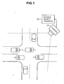
- FIG. 1 is a schematic diagram showing an intersection and a moving object tracking apparatus according to a first embodiment of the present invention, which is placed at the intersection.
- This apparatus includes an electronic camera 10 for capturing the intersection to output the captured picture signal, and a moving object tracking apparatus 20 for processing the captured pictures to track moving objects in the pictures.
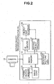
- FIG. 2 is a functional block diagram of the moving object tracking apparatus 20. Elements of the moving object tracking apparatus 20, other than a memory thereof, can be implemented using computer software, a dedicated hardware, or a combination of both.
- Time-series pictures shot by the electronic camera 10 are stored in an image memory 21 at a rate of, for example, 12 frames/sec, in which the oldest frame picture is replaced with a new frame picture.
- An image converter 22 copies each of the frame pictures stored in the image memory 21 into a frame buffer memory 23, and uses the data of the copied frame picture to convert the corresponding frame picture in the image memory 21 to a spatial differential frame picture. This conversion has two steps.
- G(i, j) be a pixel value (brightness value) at the i-th row and j-th column of the original frame picture
- H(i, j) a pixel value at the i-th row and j-th column, which is obtained through the conversion in the first step, is expressed by the following equation.
- H i j ⁇ neighborpixels G ⁇ i + di , j + dj - G i j
- the larger the pixel value the larger the absolute value of the difference between the pixel value and its neighboring pixel value.
- the value "G i,j,max” is the maximum of the pixel values of 3 ⁇ 3 neighboring pixels including the pixel of the i-th row and j-th column at the center.
- G max denotes the maximum allowable value of the pixel value G(i, j).
- the sigmoid function has a good linearity for values of H around ⁇ . Therefore, the value ⁇ is set to the most frequent value (for example, 80) in the- frequency distribution of the values of H that has edge information.
- the image converter 22 converts, on the basis of the above equations (2) and (3), pictures having pixel values G(i, j) to spatial differential frame pictures having pixel values I(i, j), which are then stored in the image memory 21.
- a background picture generator 24, an ID generation/deletion section 25, and a moving object tracking section 27 perform processing on the basis of the spatial differential frame pictures stored in the image memory 21.
- the spatial differential frame picture is simply referred to as a frame picture.
- the background picture generator 24 includes storage and processing sections. Regarding all the pictures captured for the past 10 minutes, for example, the processing section accesses the image memory 21 to produce a histogram of the pixel values of a corresponding pixel position for each pixel position, defines a picture, each pixel value of which is equal to the most frequent pixel value (i.e., mode) of the corresponding histogram, as a background picture with no moving object therein, and then stores the background picture in the storage section. This processing is repeated periodically to update the background picture.
- the processing section accesses the image memory 21 to produce a histogram of the pixel values of a corresponding pixel position for each pixel position, defines a picture, each pixel value of which is equal to the most frequent pixel value (i.e., mode) of the corresponding histogram, as a background picture with no moving object therein, and then stores the background picture in the storage section. This processing is repeated periodically to update the background picture.
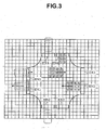
- the ID generation/deletion section 25 there are set the data of positions and sizes of slits EN1 to EN4 disposed at 4 entrances of the intersection in a frame picture and the data of positions and sizes of slits EX1 to EX4 disposed at 4 exits of the intersection.
- the ID generation/deletion section 25 reads data of images inside the entrance slits EN1 to EN4 from the image memory 21 to determine whether or not a moving object exists in each block in each entrance slit.
- Squares in meshes of FIG. 3 represent respective blocks, each block has a size of, for example, 8 x 8 pixels, and one frame is divided into 60 x 80 blocks if one frame is composed of 480 x 640 pixels.
- Whether or not a moving object exists in a block is determined on the basis of whether or not the sum of the absolute values, each of which is a difference between a pixel values in the block and a pixel value of the corresponding pixel of the background picture, is greater than a predetermined value. The determination is performed also in the moving object tracking section 27.
- the ID generation/deletion section 25 assigns a new object identification (ID) to a block when it is determined that a moving object exists in the block.
- ID object identification
- the ID generation/deletion section 25 assigns the same ID as that of the assigned adjacent block.
- This block to which an ID has been assigned may be one adjacent to an entrance slit. For example in FIG. 3 , an ID of "1" is assigned to each block in the entrance slit EN1.
- the ID assignment is performed for corresponding blocks in an object map storage section 26.
- the object map storage section 26 stores an object map having 60 x 80 blocks.
- the block information including; a flag indicating whether or not an ID has been assigned to the block; and an ID number and a block motion vector described later when the ID has been assigned.
- An ID value of "0" may be used to indicate that no 10 has been assigned, without using the flag. Further, the most significant bit of an ID may be used as the flag.
- the moving object tracking section 27 For a cluster having passed an entrance slit, the moving object tracking section 27 performs tracking with assigning the same ID to blocks in the moving direction side and deleting the ID of blocks in the reverse moving direction side. The moving object tracking section 27 performs this tracking for each cluster until inside an exit slit.
- the ID generation/deletion section 25 further checks whether or not an ID is assigned to any block in the exit slits EX1 to EX4 on the basis of information in the object map storage section 26, and if an ID has been assigned to blocks in an exit slit, the ID generation/deletion section 25 deletes the ID assigned to the blocks when the cluster having the ID has passed through the exit slit. For example in FIG. 3 , when a transition is made from a state where an ID of "3" is assigned to blocks in the exit slit EX1 to a state where no ID is assigned thereto, the ID "3" is deleted. The deleted ID can be used as the next ID to be generated.
- the moving object tracking section 27 generates an object map at time t in the storage section 26 on the basis of an object map at time (t - 1) stored in the object map storage section 26, and frame pictures at time (t - 1) and time t which are stored in the image memory 21. This procedure will now be described.
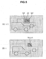
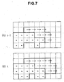
- FIGS. 4 to 7 illustrate a picture at time (t-1) and a picture at time t.
- Dotted lines in FIGS. 4 , 6 and 7 denote boundary lines between blocks, and dotted lines in FIG. 5 are boundary lines between pixels.
- B(i, j) denotes a block at the i-th row and j-th column
- B(t: i, j) denotes a block at the i-th row and j-th column at time t.
- MV motion vector of a block B(t-1: 1, 4)
- This block at time t is "B(t: 1, 5)" in the case of FIG. 4 (B) .
- the correlation between an image of the block B(t: 1, 5) and an image of a block-size region AX at time (t-1) is calculated for every block-size region AX moved pixel-by-pixel within a predetermined range AM (block matching).
- the range AM is set to be larger than the block size, and for example, one side of the range AM is 1.5 times larger than the number of pixels of corresponding one side of the block.
- the center of the range AM is a pixel located at a position to which the center of the block B(t: 1, 5) is moved by approximately -MV.
- the correlation is, for example, a space-time texture correlation. Assume that this-correlation increases as an evaluation value UD, which is the sum of the absolute values of the differences between pixel values of the block B(t: 1, 5) and corresponding pixel values of the region AX, decreases.
- a region AX in the range AM, which provides the largest correlation, is obtained, and a vector starting at the center thereof and ending at the center of the block B(1, 5) is determined to be a motion vector of the block B(t: 1, 5).
- the same ID of a block at time (t-1) nearest to the largest-correlation region AX is assigned as that of the block B(t: 1, 5).
- the moving object tracking section 27 assigns the same ID to adjacent blocks if the absolute value of the difference between motion vectors of the adjacent blocks are less than a predetermined value. This allows a cluster to be divided into a plurality of objects (moving objects) having different IDs. In FIG. 6 , a bold line indicates the boundary between objects.
- FIG. 7 which corresponds to FIG. 6 , illustrates a object map in which boundaries of the objects are shown by bold lines.
- the cluster is divided into a plurality of objects at time t1 in the same manner as described above.
- the cluster is divided into a plurality of objects in object maps at times previous to the time t1 by obtaining object maps with reverse tracking in time from time t1 in the same manner as forward tracking in time.
- individual objects are traced backward in time after one cluster is divided into a plurality of objects.
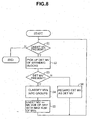
- the motion vector of such a block is estimated in a method illustrated in FIG. 8 .
- step S1 If there is a block B(i, j) whose motion vector has not been determined, then the procedure goes to step S2, else the procedure for estimating motion vectors which have not been determined is terminated.
- step S3 If any determined motion vector is present at step S2, then the procedure goes to step S4, else it goes to step S6.
- the determined motion vectors MV1 to MVn are classified into groups of motion vectors such that the absolute value of a difference between any two motion vectors in the same group is less than a predetermined value.
- the motion vector of the B(i, j) is estimated to be equal to the average of the motion vectors of one of the classified groups, which has the largest number of motion vectors. If there are a plurality of groups having the largest number of motion vectors, the motion vector of the B(i, j) is estimated to be equal to the average of the motion vectors of any one of the plurality of groups. Then the procedure returns to step S1.
- the motion vector of the B(i, j) may also be estimated to be equal to any one of the motion vectors of the same group.
- Motion vectors which have not been determined can be estimated uniquely in this manner.
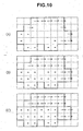
- a motion vector of a block B(i, j) at the i-th row and j-th column is denoted by MV(i, j).
- motion vectors of blocks B(2, 2), B(2, 4) and B(3, 3) are undetermined.
- FIG. 9(B) an object map as shown in FIG. 9(B) is made.
- the boundaries of the objects are indicated by bold lines.
- the motion vectors can be estimated uniquely as shown in FIG. 10(B) by repeating steps S1 to S5 until the determination of step S3 is negative. Then, the estimated motion vectors are regarded as determined motion vectors at step S6, and then steps S1 to S5 are performed once again, so that the motion vector of the block B(3, 4) is uniquely estimated as shown in FIG. 10(C) . Then, the same ID is assigned to any adjacent blocks if the absolute value of the difference between the adjacent motion vectors is less than a predetermined value. This allows one cluster to be divided into a plurality of objects having different IDs.
- the moving object tracking section 27 stores the time-series object maps stored in the object map storage section 26, as a tracking result, in a hard disk not shown.
- the unknown motion vector of a block is estimated on the basis only of motion vectors of blocks surrounding the block, so that the accuracy of estimation of the ID and motion vector of the block is reduced if there are a large number of undetermined motion vectors.
- the second embodiment of the present invention determines the IDs and motion vectors of all blocks at the same time, on the basis of values of an estimation function, which is described below.
- the moving object tracking section 27 of FIG. 2 makes and stores an object map at time t in the object map storage section 26, on the basis of both an object map at time (t-1) stored in the object map storage section 26 and frame pictures at times (t-1) and t stored in the image memory 21.
- an estimation function U(i, j) of any block B(t: i, j) including a portion of a moving object is expressed as a linear combination of four sub-estimation functions as follows.
- U i j aUD + bUM + cUN + fUV
- one block is assumed to be composed of m x m pixels
- G(t: g, h) denotes a pixel value of a pixel at the g-th row and h-th column at time t
- (MVX, MVY) denotes an estimated motion vector MV of a block B(t: i, j). It is also assumed that i ⁇ 0, and j ⁇ 0.
- the sub-estimation function UD represents a time-space texture correlation, which is the same as described in the first embodiment and is expressed by the following equation.
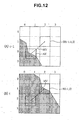
- FIG. 12 doted lines denote boundaries between blocks, and a hatched portion indicates a moving object.
- FIG. 12(B) shows an estimated motion vector "MV" of a block of interest B (t : 1, 2)
- FIG. 12 (A) shows a region "AX" to which a block B(t: 1, 2) is moved by -MV.
- an estimation function UD (1, 2, MV) of an image of the block B(t: 1, 2) and an image of the region AX is calculated. If MV is changed, the value of UD is also changed, and the smaller the value of UD, the larger the texture correlation between the image of the block B(t: 1, 2) and the image of the region AX.
- a motion vector MV which provides the smallest value of UD, is the most probable motion vector. Since there are limitations on the speed of moving objects, the minimum value of UD is calculated with moving the region AX pixel-by-pixel within a specific range from the center of the block of interest B(t: 1, 2), for example, within a range of ⁇ 25 pixels in the vertical direction and ⁇ 25 pixels in the horizontal direction. This specific range may also be a range "AM" estimated with using the motion vector at time (t - 1) as described above in the first embodiment.
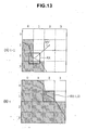
- FIGS. 13(A) and 13(B) correspond to FIGS. 12(A) and 12(B) , respectively, and hatched portions therein indicate blocks estimated that a moving object is present.
- the sub-estimation function UM indicates a space-time ID correlation and is expressed by the following equation.
- UM i j MV M - m 2 2
- the sub-estimation function UN indicates a spatial ID correlation and is expressed by the following equation.
- UN i j N - 8 2
- MV denotes the estimated motion vector of the block of interest B(t: i, j) described above item (1)
- MV neighbor denotes motion vectors of blocks having the same ID as the estimated ID of the block of interest B(t: i, j), within 8 blocks surrounding the block of interest B(t: i, j)
- ⁇ denotes a sum over blocks having the same ID
- L denotes the number of blocks having the same ID.
- UV 1 2 MV - MV ⁇ 1 + MV - MV ⁇ 2 + MV - MV ⁇ 3 + MV - MV ⁇ 4 + MV - MV ⁇ 5 / 5
- the value of UV(1, 2) is large, so that the reliability of the estimated motion vector MV is low.
- MV neighbor may be motion vectors of blocks surrounding the block of interest B(t: i, j), for example, 4 blocks on the left, right, top and bottom, one of the 8 blocks surrounding the block of interest B(t: i, j) (one round), or blocks having the same ID as the estimated ID of the block of interest B(t: i, j) within 24 blocks surrounding the block of interest B(t: i, j) (two rounds).
- MV neighbor may- be approximated by a corresponding motion vector at time (t - 1).
- the motion vector may be a motion vector of a block having the same ID as the estimated motion vector of the block of interest B(t: i, j) within blocks near the block B(t - 1,p,q).
- IDs and MVs of all the blocks at time t is determined at the same time by obtaining the minimum value of the estimation function U regarding all the blocks.
- the IDs and MVs are determined in accordance with the approximation method as shown in FIG. 11 in order to reduce processing time and thus allow real-time processing.
- a motion vector MV which minimizes the value of the estimation function UD of the above equation (2), is determined for each block that includes a portion of a moving object at time t. There is a exception that motion vectors MV are not obtained for blocks unsuitable for determining motion vectors. Then, a motion vector MV, which minimizes the value of the estimation function UV of Equation (5), is obtained for each of the blocks unsuitable for determining motion vectors. In this case, the procedure of steps S1 to S3 and S6 of FIG. 8 may be added to uniquely determine the motion vectors.
- step S15 If it is determined that steps S13 and S14 have been repeated a predetermined number of times or if it is determined that the sum UT converges to a certain value, then the procedure is terminated, else it returns to step S15.
- the motion vector MV of one block is shifted pixel-by-pixel within a predetermined range, or the ID of one block is changed. Then, the procedure returns to step S13, and if the sum UT is larger than the previous one, the changed MV or ID is restored at step S14. If the sum UT is less than the previous one, like change is made to the next block.
- the predetermined range is, for example, +4 pixels in each direction of left, right, top and bottom of the block.
- the motion vector of each of the blocks unsuitable for determining motion vectors may be determined through the procedure of steps S13 to S15 or the alternative procedure as described above.
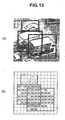
- FIGS. 15(A) and 15(B) illustrate a captured picture of an intersection, and a corresponding object map of IDs, respectively.
- Bold lines therein indicate rectangular regions, each having the same ID.
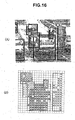
- FIGS. 16(A) and 16(B) illustrate a picture of an expressway captured at a low camera-angle, and a corresponding object map of IDs, respectively.
- FIGS. 17 (A) and 17-(B) illustrate a captured picture of a crosswalk, and a picture made by overlapping the captured crosswalk picture with a mesh of ID-assigned portions of a corresponding object map, respectively.
- Numbers assigned to rectangular regions in FIGS. 16(A) and 17(B) indicate object IDs.
- the accuracy of the object boundary is low. In this case, the tracking accuracy is also low when objects are tracked backward in time.
- the start time of the tracking backward in time is determined by performing a method as shown in FIG. 18 .
- the reliability of the object boundary is determined to be high if the correlations (space-time correlation of objects) between corresponding objects in temporally adjacent pictures within N consecutive pictures, for example, 3 consecutive pictures, are more than a predetermined value.
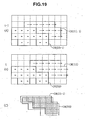
- FIG. 19(B) illustrates the object map at time t.
- step S23 If a plurality of objects are included in one cluster, then the procedure goes to step S24, else it goes to step S27.
- an area A1 (a hatched figure in FIG. 19(C) ) is determined by performing a logical AND operation between a figure, which is obtained by moving an object OBJ1 (t - 1) shown in FIG. 19(A) by an average motion vector of the object OBJ1 (t - 1), and a figure of a corresponding object OBJ1 (t) shown in FIG. 19(B) .
- An area A0 of the figure of the object OBJ1 (t - 1) is also calculated. Then, the ratio of the areas "A1/A0" is calculated as the correlation.
- the area A0 may be the area of the figure of the object OBJ1(t).
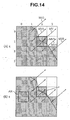
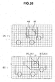
- FIG. 20 are illustrations of object maps according to the fourth embodiment of the present invention.
- the accuracy of object boundary is increased if a block size is reduced.
- the size of a block B' (i, j) used to determine the motion vector of the block B(i, j) is set to be larger than the size of the block B(i, j).
- the block B'(i, j) is concentric with the block B(i, j), and the block B(i, j) is included in the block B'(i, j).
- a block B'(t: 3, 10) is used to obtain the motion vector of a block B(t: 3, 10).
- the texture correlation between an image of the block B'(t: 3, 10) and an image of a corresponding block-size region AX at time (t - 1) is calculated for every block-size region AX moved pixel-by-pixel within a predetermined range AM.
- each block is compared with a corresponding block of the background picture to determine whether or not an object is present in the block.
- the camera shaking cannot be reflected in the background picture since the background picture is generated on the basis of pictures captured for the past, for example, 10 minutes.
- a background image is also regarded as an object in generating an object map.
- the object map generation method is same as that of any one of the first to fourth embodiments, except that it does not determine whether or not an object is present in a block on the basis of comparison with the background picture. Since a background image is also regarded as an object, block matching is performed for each block to assign an identification ID and determine a motion vector MV for each block.
- a motion vector MV which minimizes the value of the estimation function UD of Equation (2), is determined for each block at time t. However, motion vectors MV are not determined for blocks unsuitable for determining motion vectors.
- That process is performed for a picture as shown in FIG. 21(A) to obtain an object map of motion vectors as shown in FIG. 21(B) .
- dotted lines denote boundary between blocks, and dots denote motion vectors of zero.
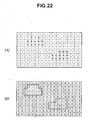
- a motion vector MV which minimizes the value of the estimation function UV of Equation (5), is obtained for each of the blocks unsuitable for determining motion vectors.
- This process makes an object map of motion vectors as shown in FIG. 22(A) .
- steps S12 to S15 is same as that of the second embodiment.
- step S12 makes an object map of IDs as shown in FIG. 22(B) .
- This method eliminates the need to use a special background picture, and also makes it possible to recognize a background picture even when the camera shakes. In addition, there is no need to set an entrance slit on the picture. Furthermore, the need to use exit slits can be eliminated by deleting the ID of an object when the object has exited the frame of a captured picture.
- a picture is divided-into blocks, and an object identification ID and an object motion vector MV are determined for each block, so that it is not possible to track a portion (for example, a block-size region) of a moving object, which is unrelated to boundaries between blocks.
- a picture is divided into blocks and an object identification ID and an object motion vector MV are determined for each block, and a portion of a moving object, which is unrelated to boundaries between the blocks, is also tracked.
- object maps OM(t) to OM(t - 5), which respectively correspond to time-series pictures at times "t” to "t - 5", have been stored in the object map storage section 26 of FIG. 2 .
- time "t” is replaced with time "t - 1", i.e., object maps OM(t) to OM(t - 5) becomes object maps OM(t - 1) to OM(t - 6), respectively.
- the oldest object map OM(t - 6) is updated to a new object map OM(t).
- the moving object tracking section 27 of FIG. 2 performs tracking of a portion of a moving object in the following manner.
- MV(t) is the motion vector of a region of interest A(t) on the object map OM(t). Dotted lines in FIG. 24(A) denote boundaries between blocks. In this example, the region of interest A(t) coincides with one block.
- a region of interest A(t - 1) on the object map OM(t - 1) is determined with moving the region of interest A(t) by -MV(t).
- a motion vector MV(t - 1) of the region of interest A(t - 1) is calculated through the use of following weighted averaging.
- MV ⁇ t - 1 MV ⁇ 1 • S ⁇ 1 + MV ⁇ 2 • S ⁇ 2 + MV ⁇ 3 • S ⁇ 3 + MV ⁇ 4 • S ⁇ 4 / S ⁇ 1 + S ⁇ 2 + S ⁇ 4
- MV1" to "MV4" denote the motion vectors of first to fourth blocks overlapping with the region of interest A(t - 1)
- S1" to "S4" denote the number of pixels of respective portions of the first to fourth blocks, which overlap with the region of interest A(t - 1).
- a region of interest A(t - 2) on the object map OM(t - 2) is obtained by moving the region of interest A(t - 1) by -MV(t - 1).
- a motion vector MV(t - 2) of the region of interest A(t - 2) is calculated in the same manner as described above.
- the sixth embodiment it is possible to track a region of interest which is a portion of a moving object, and thereby, for example, it is possible to analyze or classify a movement pattern of the region of interest or to judge it as a specific movement pattern. It is also possible to analyze or classify a movement pattern of the relative positions of a plurality of regions of interest or to judge it as a specific movement pattern.
- the motion vector of the region of interest is calculated through the use of weighted averaging as described above.
- the size of the region of interest may be smaller or larger than the block size.
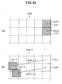
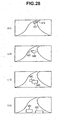
- regions of interest Ai(t - 5) and Aj(t - 5) on the object map OM(t - 5) are determined with using the method of the above sixth embodiment.
- a motion vector from the center of the region Ai(t 5) to the center of the region Ai(t) is obtained as a fast-forward motion vector MVi(t - 5, t).
- a motion vector from the center of the region Aj(t - 5) to the center of the region Aj(t) is obtained as a fast-forward motion vector MVj(t - 5, t).
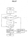
- FIG. 27 is a flow chart of a method of recognizing the boundary between moving objects in accordance with an eighth embodiment of the present invention.
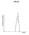
- the histogram is not made, but instead, the value "k” is changed from “0" to "kmax" for the two regions of interest of FIG. 25(A) in the following manner.
- the "kmax” is equal to, for example, "5" in the case of 10 frames/sec.
- the value "k" is automatically determined without making the histogram.
Landscapes
- Engineering & Computer Science (AREA)
- Multimedia (AREA)
- Physics & Mathematics (AREA)
- General Physics & Mathematics (AREA)
- Theoretical Computer Science (AREA)
- Computer Vision & Pattern Recognition (AREA)
- Image Analysis (AREA)
- Closed-Circuit Television Systems (AREA)
Claims (2)
- Ein Verfahren zum Verfolgen beweglicher Objekte in Zeitreihen-Bildern mit einer Bearbeitung der Bilder, wobei jedes Bild in Blöcke unterteilt ist, wobei jeder Block aus einer Vielzahl von Pixeln besteht, wobei für einen Fall, in dem in einer Blockeinheit ein Identifikationscode für ein bewegliches Objekt zugeordnet ist und ein Bewegungsvektor für ein bewegliches Objekt in einer Blockeinheit bestimmt ist, das Verfahren die folgenden Schritte umfasst:(a) Zuordnen, für jedes von N (N>=2) in den Zeitreihen-Bildern aufeinanderfolgenden Bildern, desselben Identifikationscodes zu benachbarten Blöcken, wenn ein Betrag eines Unterschieds zwischen Bewegungsvektoren der benachbarten Blöcke kleiner ist als ein vorbestimmter Wert, so dass unterschiedliche Identifikationscodes zu unterschiedlichen beweglichen Objekten, die sich in einem Bild überlappen, zugeordnet werden können, dadurch gekennzeichnet, dass es umfasst:(b) Beurteilen, ob ein erstes, aus einer Gruppe von Blöcken bestehendes Objekt, dem ein erster Identifikationscode zugeordnet wurde, und ein zweites, aus einer Gruppe von Blöcken bestehendes Objekt, dem ein zweiter Identifikationscode zugeordnet wurde, in jedem der N aufeinanderfolgenden Bildern miteinander in Kontakt stehen oder nicht, und ob eine Korrelation zwischen den ersten Objekten in allen zeitlich benachbarten Bildern in den N aufeinanderfolgenden Bildern größer ist als ein vorbestimmter Wert, wobei die Korrelation gleich einem Verhältnis einer Fläche eines Verknüpfungsglieds UND zwischen einer Figur, erhalten durch Bewegung eines der zeitlich benachbarten ersten Objekte auf der Basis eines durchschnittlichen Bewegungsvektors des einen der zeitlich benachbarten ersten Objekte und des anderen der zeitlich benachbarten ersten Objekte, zu einer Fläche des einen oder des anderen der zeitlich benachbarten ersten Objekte, und(c) zeitliches Rückverfolgen der ersten und zweiten Objekte, wenn die Beurteilung gemäß Schritt (b) positiv ist.
- Eine Vorrichtung zum Verfolgen beweglicher Objekte in Zeitreihen-Bildern, umfassend:eine Speichervorrichtung zum Speichern der Zeitreihen-Bilder sowie ein Programm, undeinen mit der Speichervorrichtung gekoppelten Prozessor,wobei das Programm den Prozessor dazu veranlasst, die Zeitreihen-Bilder zum Verfolgen der beweglichen Objekte in den Bildern zu lesen und zu verarbeiten, und durch die Verarbeitung jedes Bild in Blöcke unterteilt wird, wobei jeder Block aus einer Vielzahl von Pixeln besteht, in einer Blockeinheit ein Identifikationscode eines beweglichen Objekts zugeordnet wird und in einer Blockeinheit ein Bewegungsvektor des beweglichen Objekts bestimmt wird, wobei das Programm den Schritt umfasst:(a) Zuordnen, für jedes von N (N>=2) in den Zeitreihen-Bildern auf einanderfolgenden Bildern, desselben Identifikationscodes zu benachbarten Blöcken, wenn ein Betrag eines Unterschieds zwischen Bewegungsvektoren der benachbarten Blöcke kleiner ist als ein vorbestimmter Wert, so dass unterschiedliche Identifikationscodes zu unterschiedlichen beweglichen Objekten, die sich in einem Bild überlappen, zugeordnet werden können,(b) Beurteilen, ob ein erstes, aus einer Gruppe von Blöcken bestehendes Objekt, dem ein erster Identifikationscode zugeordnet wurde, und ein zweites, aus einer Gruppe von Blöcken bestehendes Objekt, dem ein zweiter Identifikationscode zugeordnet wurde, in jedem der N aufeinanderfolgenden Bildern miteinander in Kontakt stehen oder nicht, und ob eine Korrelation zwischen den ersten Objekten in allen zeitlich benachbarten Bildern in den N aufeinanderfolgenden Bildern größer ist als ein vorbestimmter Wert, wobei die Korrelation gleich einem Verhältnis einer Fläche eines Verknüpfungsglieds UND zwischen einer Figur, ermittelt durch Bewegung eines der zeitlich benachbarten ersten Objekte auf der Basis eines durchschnittlichen Bewegungsvektors des einen der zeitlich benachbarten ersten Objekte und des anderen der zeitlich benachbarten ersten Objekte, zu einer Fläche des einen oder des anderen der zeitlich benachbarten ersten Objekte ist, und(c) zeitliches Rückverfolgen der ersten und zweiten Objekte, wenn die Beurteilung gemäß Schritt (b) positiv ist.
Applications Claiming Priority (3)
| Application Number | Priority Date | Filing Date | Title |
|---|---|---|---|
| JP2002371047A JP4217876B2 (ja) | 2002-12-20 | 2002-12-20 | 画像における移動物体の追跡方法及び装置 |
| JP2002371047 | 2002-12-20 | ||
| PCT/JP2003/016058 WO2004057537A1 (ja) | 2002-12-20 | 2003-12-15 | 画像における移動物体の追跡方法及び装置 |
Publications (3)
| Publication Number | Publication Date |
|---|---|
| EP1574992A1 EP1574992A1 (de) | 2005-09-14 |
| EP1574992A4 EP1574992A4 (de) | 2009-11-11 |
| EP1574992B1 true EP1574992B1 (de) | 2015-03-04 |
Family
ID=32677192
Family Applications (1)
| Application Number | Title | Priority Date | Filing Date |
|---|---|---|---|
| EP03778936.9A Expired - Lifetime EP1574992B1 (de) | 2002-12-20 | 2003-12-15 | Verfahren und einrichtung zum verfolgen beweglicher objekte in bildern |
Country Status (8)
| Country | Link |
|---|---|
| US (1) | US7929613B2 (de) |
| EP (1) | EP1574992B1 (de) |
| JP (1) | JP4217876B2 (de) |
| KR (2) | KR20050085842A (de) |
| CN (1) | CN100385462C (de) |
| AU (1) | AU2003289096A1 (de) |
| CA (1) | CA2505563A1 (de) |
| WO (1) | WO2004057537A1 (de) |
Families Citing this family (41)
| Publication number | Priority date | Publication date | Assignee | Title |
|---|---|---|---|---|
| JP4714872B2 (ja) * | 2006-01-12 | 2011-06-29 | 国立大学法人 東京大学 | 画像上重畳移動物体分割方法及び装置 |
| JP4734568B2 (ja) * | 2006-01-12 | 2011-07-27 | 国立大学法人 東京大学 | 画像上移動物体計測点決定方法及び装置 |
| US8085849B1 (en) * | 2006-11-03 | 2011-12-27 | Keystream Corporation | Automated method and apparatus for estimating motion of an image segment using motion vectors from overlapping macroblocks |
| KR20080057500A (ko) * | 2006-12-20 | 2008-06-25 | 재단법인 포항산업과학연구원 | 사람 움직임 추적 시스템 및 그 방법 |
| JP2009053815A (ja) * | 2007-08-24 | 2009-03-12 | Nikon Corp | 被写体追跡プログラム、および被写体追跡装置 |
| US20090097704A1 (en) * | 2007-10-10 | 2009-04-16 | Micron Technology, Inc. | On-chip camera system for multiple object tracking and identification |
| KR100921821B1 (ko) | 2007-12-07 | 2009-10-16 | 영남대학교 산학협력단 | 특성 공간 궤적 데이터베이스 구축 방법 및 이를 이용한다중 각도 표적 식별 방법 |
| US8325976B1 (en) * | 2008-03-14 | 2012-12-04 | Verint Systems Ltd. | Systems and methods for adaptive bi-directional people counting |
| US9019381B2 (en) * | 2008-05-09 | 2015-04-28 | Intuvision Inc. | Video tracking systems and methods employing cognitive vision |
| JP4507129B2 (ja) * | 2008-06-06 | 2010-07-21 | ソニー株式会社 | 追尾点検出装置および方法、プログラム、並びに記録媒体 |
| CN101615294B (zh) * | 2008-06-26 | 2012-01-18 | 睿致科技股份有限公司 | 一种多重对象追踪的方法 |
| KR100958379B1 (ko) * | 2008-07-09 | 2010-05-17 | (주)지아트 | 복수 객체 추적 방법과 장치 및 저장매체 |
| US8325227B2 (en) * | 2008-07-15 | 2012-12-04 | Aptina Imaging Corporation | Method and apparatus for low cost motion detection |
| US20100119109A1 (en) * | 2008-11-11 | 2010-05-13 | Electronics And Telecommunications Research Institute Of Daejeon | Multi-core multi-thread based kanade-lucas-tomasi feature tracking method and apparatus |
| CN101719278B (zh) * | 2009-12-21 | 2012-01-04 | 西安电子科技大学 | 基于khm算法的视频显微图像细胞自动跟踪方法 |
| JP5561524B2 (ja) * | 2010-03-19 | 2014-07-30 | ソニー株式会社 | 画像処理装置および方法、並びにプログラム |
| JP5338978B2 (ja) * | 2010-05-10 | 2013-11-13 | 富士通株式会社 | 画像処理装置および画像処理プログラム |
| JP5459154B2 (ja) * | 2010-09-15 | 2014-04-02 | トヨタ自動車株式会社 | 車両用周囲画像表示装置及び方法 |
| JP5218861B2 (ja) * | 2010-09-30 | 2013-06-26 | 株式会社Jvcケンウッド | 目標追跡装置、目標追跡方法 |
| JP5828210B2 (ja) * | 2010-10-19 | 2015-12-02 | ソニー株式会社 | 画像処理装置および方法、並びに、プログラム |
| US10018703B2 (en) * | 2012-09-13 | 2018-07-10 | Conduent Business Services, Llc | Method for stop sign law enforcement using motion vectors in video streams |
| WO2013077562A1 (ko) * | 2011-11-24 | 2013-05-30 | 에스케이플래닛 주식회사 | 특징점 설정 장치 및 방법과 이를 이용한 객체 추적 장치 및 방법 |
| KR101939628B1 (ko) | 2012-05-30 | 2019-01-17 | 삼성전자주식회사 | 모션 검출 방법 및 모션 검출기 |
| CN103678299B (zh) * | 2012-08-30 | 2018-03-23 | 中兴通讯股份有限公司 | 一种监控视频摘要的方法及装置 |
| US9311338B2 (en) * | 2013-08-26 | 2016-04-12 | Adobe Systems Incorporated | Method and apparatus for analyzing and associating behaviors to image content |
| KR102161212B1 (ko) | 2013-11-25 | 2020-09-29 | 한화테크윈 주식회사 | 움직임 검출 시스템 및 방법 |
| US9598011B2 (en) * | 2014-01-09 | 2017-03-21 | Northrop Grumman Systems Corporation | Artificial vision system |
| US10290287B1 (en) * | 2014-07-01 | 2019-05-14 | Xilinx, Inc. | Visualizing operation of a memory controller |
| CN104539864B (zh) * | 2014-12-23 | 2018-02-02 | 小米科技有限责任公司 | 记录图像的方法和装置 |
| CN106296725B (zh) * | 2015-06-12 | 2021-10-19 | 富泰华工业(深圳)有限公司 | 运动目标实时检测与跟踪方法及目标检测装置 |
| CN105719315B (zh) * | 2016-01-29 | 2019-01-22 | 深圳先进技术研究院 | 用于在移动终端中跟踪视频图像中的物体的方法 |
| JP6526589B2 (ja) * | 2016-03-14 | 2019-06-05 | 株式会社東芝 | 画像処理デバイス及び画像処理プログラム |
| KR102553598B1 (ko) * | 2016-11-18 | 2023-07-10 | 삼성전자주식회사 | 영상 처리 장치 및 그 제어 방법 |
| US11405581B2 (en) * | 2017-12-26 | 2022-08-02 | Pixart Imaging Inc. | Motion detection methods and image sensor devices capable of generating ranking list of regions of interest and pre-recording monitoring images |
| JP7227969B2 (ja) * | 2018-05-30 | 2023-02-22 | パナソニック インテレクチュアル プロパティ コーポレーション オブ アメリカ | 三次元再構成方法および三次元再構成装置 |
| CN111105434B (zh) * | 2018-10-25 | 2025-05-30 | 中兴通讯股份有限公司 | 运动轨迹合成方法及电子设备 |
| CN111192286B (zh) * | 2018-11-14 | 2025-02-21 | 西安中兴新软件有限责任公司 | 一种图像合成方法、电子设备及存储介质 |
| CN109584575B (zh) * | 2018-12-19 | 2020-09-18 | 山东交通学院 | 一种基于能见度分析的道路安全限速提示系统及方法 |
| US11277723B2 (en) | 2018-12-27 | 2022-03-15 | Continental Automotive Systems, Inc. | Stabilization grid for sensors mounted on infrastructure |
| KR102264208B1 (ko) * | 2019-12-10 | 2021-06-11 | 한국전자기술연구원 | 중복 영역 객체 검출 개선을 위한 의미적 필터링 모듈 시스템 |
| US20210110552A1 (en) * | 2020-12-21 | 2021-04-15 | Intel Corporation | Methods and apparatus to improve driver-assistance vision systems using object detection based on motion vectors |
Family Cites Families (16)
| Publication number | Priority date | Publication date | Assignee | Title |
|---|---|---|---|---|
| JP2687974B2 (ja) * | 1986-03-31 | 1997-12-08 | 日本放送協会 | 動きベクトル検出方法 |
| JP3252415B2 (ja) * | 1991-11-15 | 2002-02-04 | ソニー株式会社 | 画像の手振れ補正装置 |
| US6002428A (en) * | 1994-10-21 | 1999-12-14 | Sanyo Electric Co., Ltd. | Motion vector detection circuit and object tracking camera device utilizing the same |
| JPH09161071A (ja) * | 1995-12-12 | 1997-06-20 | Sony Corp | 領域対応付け装置および領域対応付け方法 |
| JPH09185720A (ja) * | 1995-12-28 | 1997-07-15 | Canon Inc | 画像抽出装置 |
| JP3434979B2 (ja) * | 1996-07-23 | 2003-08-11 | 富士通株式会社 | 局所領域画像追跡装置 |
| KR100501902B1 (ko) * | 1996-09-25 | 2005-10-10 | 주식회사 팬택앤큐리텔 | 영상정보부호화/복호화장치및방법 |
| KR100244291B1 (ko) * | 1997-07-30 | 2000-02-01 | 구본준 | 동영상 움직임 벡터 코딩 방법 |
| DE69935655T2 (de) * | 1998-09-29 | 2007-12-27 | Koninklijke Philips Electronics N.V. | Verfahren und vorrichtung zum zerlegungskomprimieren |
| JP4377474B2 (ja) * | 1999-03-31 | 2009-12-02 | 株式会社東芝 | 移動体の衝突防止装置、衝突防止方法、および記録媒体 |
| US6968004B1 (en) * | 1999-08-04 | 2005-11-22 | Kabushiki Kaisha Toshiba | Method of describing object region data, apparatus for generating object region data, video processing method, and video processing apparatus |
| US7367042B1 (en) * | 2000-02-29 | 2008-04-29 | Goldpocket Interactive, Inc. | Method and apparatus for hyperlinking in a television broadcast |
| JP4201958B2 (ja) * | 2000-04-26 | 2008-12-24 | 日本放送協会 | 動画像のオブジェクト抽出装置 |
| JP3920535B2 (ja) * | 2000-06-12 | 2007-05-30 | 株式会社日立製作所 | 車両検出方法及び車両検出装置 |
| JP2002133421A (ja) * | 2000-10-18 | 2002-05-10 | Fujitsu Ltd | 移動物体認識方法及び装置 |
| US20030161399A1 (en) * | 2002-02-22 | 2003-08-28 | Koninklijke Philips Electronics N.V. | Multi-layer composite objective image quality metric |
-
2002
- 2002-12-20 JP JP2002371047A patent/JP4217876B2/ja not_active Expired - Lifetime
-
2003
- 2003-12-15 AU AU2003289096A patent/AU2003289096A1/en not_active Abandoned
- 2003-12-15 US US10/540,217 patent/US7929613B2/en not_active Expired - Fee Related
- 2003-12-15 CN CNB2003801069714A patent/CN100385462C/zh not_active Expired - Fee Related
- 2003-12-15 KR KR1020057011609A patent/KR20050085842A/ko not_active Ceased
- 2003-12-15 EP EP03778936.9A patent/EP1574992B1/de not_active Expired - Lifetime
- 2003-12-15 CA CA002505563A patent/CA2505563A1/en not_active Abandoned
- 2003-12-15 KR KR1020077010090A patent/KR20070065418A/ko not_active Ceased
- 2003-12-15 WO PCT/JP2003/016058 patent/WO2004057537A1/ja not_active Ceased
Also Published As
| Publication number | Publication date |
|---|---|
| US20060092280A1 (en) | 2006-05-04 |
| AU2003289096A1 (en) | 2004-07-14 |
| JP4217876B2 (ja) | 2009-02-04 |
| US7929613B2 (en) | 2011-04-19 |
| KR20070065418A (ko) | 2007-06-22 |
| CA2505563A1 (en) | 2004-07-08 |
| CN100385462C (zh) | 2008-04-30 |
| EP1574992A4 (de) | 2009-11-11 |
| WO2004057537A1 (ja) | 2004-07-08 |
| EP1574992A1 (de) | 2005-09-14 |
| KR20050085842A (ko) | 2005-08-29 |
| CN1729485A (zh) | 2006-02-01 |
| JP2004207786A (ja) | 2004-07-22 |
Similar Documents
| Publication | Publication Date | Title |
|---|---|---|
| EP1574992B1 (de) | Verfahren und einrichtung zum verfolgen beweglicher objekte in bildern | |
| KR100377067B1 (ko) | 이미지 시퀀스내의 객체의 움직임을 검출하기 위한 방법 및장치 | |
| EP1844443B1 (de) | Klassifizierung eines objekts in einem videorahmen | |
| JP4782123B2 (ja) | カメラによりシーンに関して取得された映像中の移動物体を追跡する方法 | |
| US7149328B2 (en) | Method and apparatus for tracking moving objects in spatial differential frame pictures | |
| JP5371040B2 (ja) | 移動物体追跡装置、移動物体追跡方法および移動物体追跡プログラム | |
| JP2003162798A (ja) | 障害物監視装置及びプログラム | |
| JP2002133421A (ja) | 移動物体認識方法及び装置 | |
| JPH10105690A (ja) | 広域移動体追跡装置 | |
| JP4543106B2 (ja) | 画像における移動物体の追跡方法及び装置 | |
| Kim et al. | Unsupervised moving object segmentation and recognition using clustering and a neural network | |
| JP3502468B2 (ja) | 分散型監視装置 | |
| Denman et al. | Multi-view intelligent vehicle surveillance system | |
| JP3763279B2 (ja) | 物体抽出システム、物体抽出方法および物体抽出プログラム | |
| JP3505924B2 (ja) | 車両監視装置 | |
| WO2019045586A1 (ru) | Способ мониторинга движущихся объектов | |
| Suemitsu et al. | Selection of Dash Cam Images for Weather Forecasting Based on The Sky Occupancy | |
| Lim et al. | Detection and tracking multiple pedestrians from a moving camera | |
| JP3678273B2 (ja) | 画像認識による移動体数量測定システム及び移動体数量測定方法 | |
| JP4923268B2 (ja) | 画像における移動物体の追跡方法及び装置 | |
| JP5165103B2 (ja) | 画像における移動物体の追跡方法及び装置 | |
| Harasse et al. | Multiple faces tracking using local statistics | |
| Yun | Background-Centric Approach for Moving Object Detection in Moving Cameras | |
| CN121392789A (zh) | 一种基于深度学习的跨摄像机路边停车智能识别方法 | |
| Veeraraghavan et al. | Managing suburban intersections through sensing |
Legal Events
| Date | Code | Title | Description |
|---|---|---|---|
| PUAI | Public reference made under article 153(3) epc to a published international application that has entered the european phase |
Free format text: ORIGINAL CODE: 0009012 |
|
| 17P | Request for examination filed |
Effective date: 20050517 |
|
| AK | Designated contracting states |
Kind code of ref document: A1 Designated state(s): AT BE BG CH CY CZ DE DK EE ES FI FR GB GR HU IE IT LI LU MC NL PT RO SE SI SK TR |
|
| AX | Request for extension of the european patent |
Extension state: AL LT LV MK |
|
| RBV | Designated contracting states (corrected) |
Designated state(s): AT BE BG CH CY CZ DE DK EE ES FI FR GB GR HU IE IT LI LU MC NL PT RO SE SI SK TR |
|
| RTI1 | Title (correction) |
Free format text: METHOD AND DEVICE FOR TRACKING MOVING OBJECTS IN IMAGES |
|
| DAX | Request for extension of the european patent (deleted) | ||
| RBV | Designated contracting states (corrected) |
Designated state(s): DE FR GB IT |
|
| A4 | Supplementary search report drawn up and despatched |
Effective date: 20090903 |
|
| 17Q | First examination report despatched |
Effective date: 20091117 |
|
| GRAP | Despatch of communication of intention to grant a patent |
Free format text: ORIGINAL CODE: EPIDOSNIGR1 |
|
| INTG | Intention to grant announced |
Effective date: 20141013 |
|
| GRAS | Grant fee paid |
Free format text: ORIGINAL CODE: EPIDOSNIGR3 |
|
| GRAA | (expected) grant |
Free format text: ORIGINAL CODE: 0009210 |
|
| AK | Designated contracting states |
Kind code of ref document: B1 Designated state(s): DE FR GB IT |
|
| REG | Reference to a national code |
Ref country code: GB Ref legal event code: FG4D |
|
| REG | Reference to a national code |
Ref country code: DE Ref legal event code: R096 Ref document number: 60347379 Country of ref document: DE Effective date: 20150416 |
|
| REG | Reference to a national code |
Ref country code: DE Ref legal event code: R097 Ref document number: 60347379 Country of ref document: DE |
|
| REG | Reference to a national code |
Ref country code: FR Ref legal event code: PLFP Year of fee payment: 13 |
|
| PG25 | Lapsed in a contracting state [announced via postgrant information from national office to epo] |
Ref country code: IT Free format text: LAPSE BECAUSE OF FAILURE TO SUBMIT A TRANSLATION OF THE DESCRIPTION OR TO PAY THE FEE WITHIN THE PRESCRIBED TIME-LIMIT Effective date: 20150304 |
|
| PLBE | No opposition filed within time limit |
Free format text: ORIGINAL CODE: 0009261 |
|
| STAA | Information on the status of an ep patent application or granted ep patent |
Free format text: STATUS: NO OPPOSITION FILED WITHIN TIME LIMIT |
|
| 26N | No opposition filed |
Effective date: 20151207 |
|
| PGFP | Annual fee paid to national office [announced via postgrant information from national office to epo] |
Ref country code: FR Payment date: 20151218 Year of fee payment: 13 |
|
| PGFP | Annual fee paid to national office [announced via postgrant information from national office to epo] |
Ref country code: DE Payment date: 20160222 Year of fee payment: 13 |
|
| GBPC | Gb: european patent ceased through non-payment of renewal fee |
Effective date: 20151215 |
|
| PG25 | Lapsed in a contracting state [announced via postgrant information from national office to epo] |
Ref country code: GB Free format text: LAPSE BECAUSE OF NON-PAYMENT OF DUE FEES Effective date: 20151215 |
|
| REG | Reference to a national code |
Ref country code: DE Ref legal event code: R119 Ref document number: 60347379 Country of ref document: DE |
|
| REG | Reference to a national code |
Ref country code: FR Ref legal event code: ST Effective date: 20170831 |
|
| PG25 | Lapsed in a contracting state [announced via postgrant information from national office to epo] |
Ref country code: FR Free format text: LAPSE BECAUSE OF NON-PAYMENT OF DUE FEES Effective date: 20170102 |
|
| PG25 | Lapsed in a contracting state [announced via postgrant information from national office to epo] |
Ref country code: DE Free format text: LAPSE BECAUSE OF NON-PAYMENT OF DUE FEES Effective date: 20170701 |