EP1574992B1 - Method and device for tracking moving objects in images - Google Patents
Method and device for tracking moving objects in images Download PDFInfo
- Publication number
- EP1574992B1 EP1574992B1 EP03778936.9A EP03778936A EP1574992B1 EP 1574992 B1 EP1574992 B1 EP 1574992B1 EP 03778936 A EP03778936 A EP 03778936A EP 1574992 B1 EP1574992 B1 EP 1574992B1
- Authority
- EP
- European Patent Office
- Prior art keywords
- block
- objects
- time
- pictures
- blocks
- Prior art date
- Legal status (The legal status is an assumption and is not a legal conclusion. Google has not performed a legal analysis and makes no representation as to the accuracy of the status listed.)
- Expired - Lifetime
Links
Images


Classifications
-
- G—PHYSICS
- G06—COMPUTING OR CALCULATING; COUNTING
- G06T—IMAGE DATA PROCESSING OR GENERATION, IN GENERAL
- G06T7/00—Image analysis
- G06T7/20—Analysis of motion
-
- G—PHYSICS
- G06—COMPUTING OR CALCULATING; COUNTING
- G06T—IMAGE DATA PROCESSING OR GENERATION, IN GENERAL
- G06T7/00—Image analysis
- G06T7/20—Analysis of motion
- G06T7/223—Analysis of motion using block-matching
- G06T7/231—Analysis of motion using block-matching using full search
-
- G—PHYSICS
- G06—COMPUTING OR CALCULATING; COUNTING
- G06V—IMAGE OR VIDEO RECOGNITION OR UNDERSTANDING
- G06V10/00—Arrangements for image or video recognition or understanding
- G06V10/20—Image preprocessing
- G06V10/255—Detecting or recognising potential candidate objects based on visual cues, e.g. shapes
-
- G—PHYSICS
- G06—COMPUTING OR CALCULATING; COUNTING
- G06V—IMAGE OR VIDEO RECOGNITION OR UNDERSTANDING
- G06V20/00—Scenes; Scene-specific elements
- G06V20/50—Context or environment of the image
- G06V20/52—Surveillance or monitoring of activities, e.g. for recognising suspicious objects
- G06V20/54—Surveillance or monitoring of activities, e.g. for recognising suspicious objects of traffic, e.g. cars on the road, trains or boats
-
- G—PHYSICS
- G06—COMPUTING OR CALCULATING; COUNTING
- G06T—IMAGE DATA PROCESSING OR GENERATION, IN GENERAL
- G06T2207/00—Indexing scheme for image analysis or image enhancement
- G06T2207/10—Image acquisition modality
- G06T2207/10016—Video; Image sequence
-
- G—PHYSICS
- G06—COMPUTING OR CALCULATING; COUNTING
- G06T—IMAGE DATA PROCESSING OR GENERATION, IN GENERAL
- G06T2207/00—Indexing scheme for image analysis or image enhancement
- G06T2207/30—Subject of image; Context of image processing
- G06T2207/30236—Traffic on road, railway or crossing
-
- G—PHYSICS
- G06—COMPUTING OR CALCULATING; COUNTING
- G06V—IMAGE OR VIDEO RECOGNITION OR UNDERSTANDING
- G06V2201/00—Indexing scheme relating to image or video recognition or understanding
- G06V2201/08—Detecting or categorising vehicles
Definitions
- the present invention relates to a method and apparatus for tracking moving objects (i.e., movable things such as cars, bicycles, and animals) in pictures by processing time-series pictures to-track the moving objects therein.
- moving objects i.e., movable things such as cars, bicycles, and animals
- S-T MRF Spatio-Temporal Markov Random Field model
- This method makes it possible to track vehicles M1 and M2 using a single camera.
- each captured picture is divided into blocks, each of which has a size of, for example, 8 x 8 pixels, and the image of each block of a captured picture and the image of a corresponding block of a separate background picture are compared to determine whether or not an moving object is present in the block.
- the background picture must be updated since it varies with time.
- a histogram of the pixel values of a corresponding pixel position is made for each pixel position, and a picture, each pixel value of which is equal to the most frequent pixel value (i.e., mode) of the corresponding histogram, is defined as a background picture.
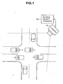
- FIG. 1 is a schematic diagram showing an intersection and a moving object tracking apparatus according to a first embodiment of the present invention, which is placed at the intersection.
- This apparatus includes an electronic camera 10 for capturing the intersection to output the captured picture signal, and a moving object tracking apparatus 20 for processing the captured pictures to track moving objects in the pictures.
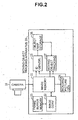
- FIG. 2 is a functional block diagram of the moving object tracking apparatus 20. Elements of the moving object tracking apparatus 20, other than a memory thereof, can be implemented using computer software, a dedicated hardware, or a combination of both.
- Time-series pictures shot by the electronic camera 10 are stored in an image memory 21 at a rate of, for example, 12 frames/sec, in which the oldest frame picture is replaced with a new frame picture.
- An image converter 22 copies each of the frame pictures stored in the image memory 21 into a frame buffer memory 23, and uses the data of the copied frame picture to convert the corresponding frame picture in the image memory 21 to a spatial differential frame picture. This conversion has two steps.
- G(i, j) be a pixel value (brightness value) at the i-th row and j-th column of the original frame picture
- H(i, j) a pixel value at the i-th row and j-th column, which is obtained through the conversion in the first step, is expressed by the following equation.
- H i j ⁇ neighborpixels G ⁇ i + di , j + dj - G i j
- the larger the pixel value the larger the absolute value of the difference between the pixel value and its neighboring pixel value.
- the value "G i,j,max” is the maximum of the pixel values of 3 ⁇ 3 neighboring pixels including the pixel of the i-th row and j-th column at the center.
- G max denotes the maximum allowable value of the pixel value G(i, j).
- the sigmoid function has a good linearity for values of H around ⁇ . Therefore, the value ⁇ is set to the most frequent value (for example, 80) in the- frequency distribution of the values of H that has edge information.
- the image converter 22 converts, on the basis of the above equations (2) and (3), pictures having pixel values G(i, j) to spatial differential frame pictures having pixel values I(i, j), which are then stored in the image memory 21.
- a background picture generator 24, an ID generation/deletion section 25, and a moving object tracking section 27 perform processing on the basis of the spatial differential frame pictures stored in the image memory 21.
- the spatial differential frame picture is simply referred to as a frame picture.
- the background picture generator 24 includes storage and processing sections. Regarding all the pictures captured for the past 10 minutes, for example, the processing section accesses the image memory 21 to produce a histogram of the pixel values of a corresponding pixel position for each pixel position, defines a picture, each pixel value of which is equal to the most frequent pixel value (i.e., mode) of the corresponding histogram, as a background picture with no moving object therein, and then stores the background picture in the storage section. This processing is repeated periodically to update the background picture.
- the processing section accesses the image memory 21 to produce a histogram of the pixel values of a corresponding pixel position for each pixel position, defines a picture, each pixel value of which is equal to the most frequent pixel value (i.e., mode) of the corresponding histogram, as a background picture with no moving object therein, and then stores the background picture in the storage section. This processing is repeated periodically to update the background picture.
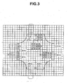
- the ID generation/deletion section 25 there are set the data of positions and sizes of slits EN1 to EN4 disposed at 4 entrances of the intersection in a frame picture and the data of positions and sizes of slits EX1 to EX4 disposed at 4 exits of the intersection.
- the ID generation/deletion section 25 reads data of images inside the entrance slits EN1 to EN4 from the image memory 21 to determine whether or not a moving object exists in each block in each entrance slit.
- Squares in meshes of FIG. 3 represent respective blocks, each block has a size of, for example, 8 x 8 pixels, and one frame is divided into 60 x 80 blocks if one frame is composed of 480 x 640 pixels.
- Whether or not a moving object exists in a block is determined on the basis of whether or not the sum of the absolute values, each of which is a difference between a pixel values in the block and a pixel value of the corresponding pixel of the background picture, is greater than a predetermined value. The determination is performed also in the moving object tracking section 27.
- the ID generation/deletion section 25 assigns a new object identification (ID) to a block when it is determined that a moving object exists in the block.
- ID object identification
- the ID generation/deletion section 25 assigns the same ID as that of the assigned adjacent block.
- This block to which an ID has been assigned may be one adjacent to an entrance slit. For example in FIG. 3 , an ID of "1" is assigned to each block in the entrance slit EN1.
- the ID assignment is performed for corresponding blocks in an object map storage section 26.
- the object map storage section 26 stores an object map having 60 x 80 blocks.
- the block information including; a flag indicating whether or not an ID has been assigned to the block; and an ID number and a block motion vector described later when the ID has been assigned.
- An ID value of "0" may be used to indicate that no 10 has been assigned, without using the flag. Further, the most significant bit of an ID may be used as the flag.
- the moving object tracking section 27 For a cluster having passed an entrance slit, the moving object tracking section 27 performs tracking with assigning the same ID to blocks in the moving direction side and deleting the ID of blocks in the reverse moving direction side. The moving object tracking section 27 performs this tracking for each cluster until inside an exit slit.
- the ID generation/deletion section 25 further checks whether or not an ID is assigned to any block in the exit slits EX1 to EX4 on the basis of information in the object map storage section 26, and if an ID has been assigned to blocks in an exit slit, the ID generation/deletion section 25 deletes the ID assigned to the blocks when the cluster having the ID has passed through the exit slit. For example in FIG. 3 , when a transition is made from a state where an ID of "3" is assigned to blocks in the exit slit EX1 to a state where no ID is assigned thereto, the ID "3" is deleted. The deleted ID can be used as the next ID to be generated.
- the moving object tracking section 27 generates an object map at time t in the storage section 26 on the basis of an object map at time (t - 1) stored in the object map storage section 26, and frame pictures at time (t - 1) and time t which are stored in the image memory 21. This procedure will now be described.
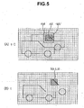
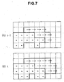
- FIGS. 4 to 7 illustrate a picture at time (t-1) and a picture at time t.
- Dotted lines in FIGS. 4 , 6 and 7 denote boundary lines between blocks, and dotted lines in FIG. 5 are boundary lines between pixels.
- B(i, j) denotes a block at the i-th row and j-th column
- B(t: i, j) denotes a block at the i-th row and j-th column at time t.
- MV motion vector of a block B(t-1: 1, 4)
- This block at time t is "B(t: 1, 5)" in the case of FIG. 4 (B) .
- the correlation between an image of the block B(t: 1, 5) and an image of a block-size region AX at time (t-1) is calculated for every block-size region AX moved pixel-by-pixel within a predetermined range AM (block matching).
- the range AM is set to be larger than the block size, and for example, one side of the range AM is 1.5 times larger than the number of pixels of corresponding one side of the block.
- the center of the range AM is a pixel located at a position to which the center of the block B(t: 1, 5) is moved by approximately -MV.
- the correlation is, for example, a space-time texture correlation. Assume that this-correlation increases as an evaluation value UD, which is the sum of the absolute values of the differences between pixel values of the block B(t: 1, 5) and corresponding pixel values of the region AX, decreases.
- a region AX in the range AM, which provides the largest correlation, is obtained, and a vector starting at the center thereof and ending at the center of the block B(1, 5) is determined to be a motion vector of the block B(t: 1, 5).
- the same ID of a block at time (t-1) nearest to the largest-correlation region AX is assigned as that of the block B(t: 1, 5).
- the moving object tracking section 27 assigns the same ID to adjacent blocks if the absolute value of the difference between motion vectors of the adjacent blocks are less than a predetermined value. This allows a cluster to be divided into a plurality of objects (moving objects) having different IDs. In FIG. 6 , a bold line indicates the boundary between objects.
- FIG. 7 which corresponds to FIG. 6 , illustrates a object map in which boundaries of the objects are shown by bold lines.
- the cluster is divided into a plurality of objects at time t1 in the same manner as described above.
- the cluster is divided into a plurality of objects in object maps at times previous to the time t1 by obtaining object maps with reverse tracking in time from time t1 in the same manner as forward tracking in time.
- individual objects are traced backward in time after one cluster is divided into a plurality of objects.
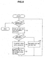
- the motion vector of such a block is estimated in a method illustrated in FIG. 8 .
- step S1 If there is a block B(i, j) whose motion vector has not been determined, then the procedure goes to step S2, else the procedure for estimating motion vectors which have not been determined is terminated.
- step S3 If any determined motion vector is present at step S2, then the procedure goes to step S4, else it goes to step S6.
- the determined motion vectors MV1 to MVn are classified into groups of motion vectors such that the absolute value of a difference between any two motion vectors in the same group is less than a predetermined value.
- the motion vector of the B(i, j) is estimated to be equal to the average of the motion vectors of one of the classified groups, which has the largest number of motion vectors. If there are a plurality of groups having the largest number of motion vectors, the motion vector of the B(i, j) is estimated to be equal to the average of the motion vectors of any one of the plurality of groups. Then the procedure returns to step S1.
- the motion vector of the B(i, j) may also be estimated to be equal to any one of the motion vectors of the same group.
- Motion vectors which have not been determined can be estimated uniquely in this manner.
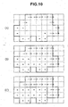
- a motion vector of a block B(i, j) at the i-th row and j-th column is denoted by MV(i, j).
- motion vectors of blocks B(2, 2), B(2, 4) and B(3, 3) are undetermined.
- FIG. 9(B) an object map as shown in FIG. 9(B) is made.
- the boundaries of the objects are indicated by bold lines.
- the motion vectors can be estimated uniquely as shown in FIG. 10(B) by repeating steps S1 to S5 until the determination of step S3 is negative. Then, the estimated motion vectors are regarded as determined motion vectors at step S6, and then steps S1 to S5 are performed once again, so that the motion vector of the block B(3, 4) is uniquely estimated as shown in FIG. 10(C) . Then, the same ID is assigned to any adjacent blocks if the absolute value of the difference between the adjacent motion vectors is less than a predetermined value. This allows one cluster to be divided into a plurality of objects having different IDs.
- the moving object tracking section 27 stores the time-series object maps stored in the object map storage section 26, as a tracking result, in a hard disk not shown.
- the unknown motion vector of a block is estimated on the basis only of motion vectors of blocks surrounding the block, so that the accuracy of estimation of the ID and motion vector of the block is reduced if there are a large number of undetermined motion vectors.
- the second embodiment of the present invention determines the IDs and motion vectors of all blocks at the same time, on the basis of values of an estimation function, which is described below.
- the moving object tracking section 27 of FIG. 2 makes and stores an object map at time t in the object map storage section 26, on the basis of both an object map at time (t-1) stored in the object map storage section 26 and frame pictures at times (t-1) and t stored in the image memory 21.
- an estimation function U(i, j) of any block B(t: i, j) including a portion of a moving object is expressed as a linear combination of four sub-estimation functions as follows.
- U i j aUD + bUM + cUN + fUV
- one block is assumed to be composed of m x m pixels
- G(t: g, h) denotes a pixel value of a pixel at the g-th row and h-th column at time t
- (MVX, MVY) denotes an estimated motion vector MV of a block B(t: i, j). It is also assumed that i ⁇ 0, and j ⁇ 0.
- the sub-estimation function UD represents a time-space texture correlation, which is the same as described in the first embodiment and is expressed by the following equation.
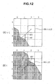
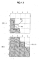
- FIG. 12 doted lines denote boundaries between blocks, and a hatched portion indicates a moving object.
- FIG. 12(B) shows an estimated motion vector "MV" of a block of interest B (t : 1, 2)
- FIG. 12 (A) shows a region "AX" to which a block B(t: 1, 2) is moved by -MV.
- an estimation function UD (1, 2, MV) of an image of the block B(t: 1, 2) and an image of the region AX is calculated. If MV is changed, the value of UD is also changed, and the smaller the value of UD, the larger the texture correlation between the image of the block B(t: 1, 2) and the image of the region AX.
- a motion vector MV which provides the smallest value of UD, is the most probable motion vector. Since there are limitations on the speed of moving objects, the minimum value of UD is calculated with moving the region AX pixel-by-pixel within a specific range from the center of the block of interest B(t: 1, 2), for example, within a range of ⁇ 25 pixels in the vertical direction and ⁇ 25 pixels in the horizontal direction. This specific range may also be a range "AM" estimated with using the motion vector at time (t - 1) as described above in the first embodiment.
- FIGS. 13(A) and 13(B) correspond to FIGS. 12(A) and 12(B) , respectively, and hatched portions therein indicate blocks estimated that a moving object is present.
- the sub-estimation function UM indicates a space-time ID correlation and is expressed by the following equation.
- UM i j MV M - m 2 2
- the sub-estimation function UN indicates a spatial ID correlation and is expressed by the following equation.
- UN i j N - 8 2
- MV denotes the estimated motion vector of the block of interest B(t: i, j) described above item (1)
- MV neighbor denotes motion vectors of blocks having the same ID as the estimated ID of the block of interest B(t: i, j), within 8 blocks surrounding the block of interest B(t: i, j)
- ⁇ denotes a sum over blocks having the same ID
- L denotes the number of blocks having the same ID.
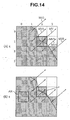
- UV 1 2 MV - MV ⁇ 1 + MV - MV ⁇ 2 + MV - MV ⁇ 3 + MV - MV ⁇ 4 + MV - MV ⁇ 5 / 5
- the value of UV(1, 2) is large, so that the reliability of the estimated motion vector MV is low.
- MV neighbor may be motion vectors of blocks surrounding the block of interest B(t: i, j), for example, 4 blocks on the left, right, top and bottom, one of the 8 blocks surrounding the block of interest B(t: i, j) (one round), or blocks having the same ID as the estimated ID of the block of interest B(t: i, j) within 24 blocks surrounding the block of interest B(t: i, j) (two rounds).
- MV neighbor may- be approximated by a corresponding motion vector at time (t - 1).
- the motion vector may be a motion vector of a block having the same ID as the estimated motion vector of the block of interest B(t: i, j) within blocks near the block B(t - 1,p,q).
- IDs and MVs of all the blocks at time t is determined at the same time by obtaining the minimum value of the estimation function U regarding all the blocks.
- the IDs and MVs are determined in accordance with the approximation method as shown in FIG. 11 in order to reduce processing time and thus allow real-time processing.
- a motion vector MV which minimizes the value of the estimation function UD of the above equation (2), is determined for each block that includes a portion of a moving object at time t. There is a exception that motion vectors MV are not obtained for blocks unsuitable for determining motion vectors. Then, a motion vector MV, which minimizes the value of the estimation function UV of Equation (5), is obtained for each of the blocks unsuitable for determining motion vectors. In this case, the procedure of steps S1 to S3 and S6 of FIG. 8 may be added to uniquely determine the motion vectors.
- step S15 If it is determined that steps S13 and S14 have been repeated a predetermined number of times or if it is determined that the sum UT converges to a certain value, then the procedure is terminated, else it returns to step S15.
- the motion vector MV of one block is shifted pixel-by-pixel within a predetermined range, or the ID of one block is changed. Then, the procedure returns to step S13, and if the sum UT is larger than the previous one, the changed MV or ID is restored at step S14. If the sum UT is less than the previous one, like change is made to the next block.
- the predetermined range is, for example, +4 pixels in each direction of left, right, top and bottom of the block.
- the motion vector of each of the blocks unsuitable for determining motion vectors may be determined through the procedure of steps S13 to S15 or the alternative procedure as described above.
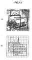
- FIGS. 15(A) and 15(B) illustrate a captured picture of an intersection, and a corresponding object map of IDs, respectively.
- Bold lines therein indicate rectangular regions, each having the same ID.
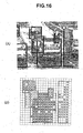
- FIGS. 16(A) and 16(B) illustrate a picture of an expressway captured at a low camera-angle, and a corresponding object map of IDs, respectively.
- FIGS. 17 (A) and 17-(B) illustrate a captured picture of a crosswalk, and a picture made by overlapping the captured crosswalk picture with a mesh of ID-assigned portions of a corresponding object map, respectively.
- Numbers assigned to rectangular regions in FIGS. 16(A) and 17(B) indicate object IDs.
- the accuracy of the object boundary is low. In this case, the tracking accuracy is also low when objects are tracked backward in time.
- the start time of the tracking backward in time is determined by performing a method as shown in FIG. 18 .
- the reliability of the object boundary is determined to be high if the correlations (space-time correlation of objects) between corresponding objects in temporally adjacent pictures within N consecutive pictures, for example, 3 consecutive pictures, are more than a predetermined value.
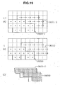
- FIG. 19(B) illustrates the object map at time t.
- step S23 If a plurality of objects are included in one cluster, then the procedure goes to step S24, else it goes to step S27.
- an area A1 (a hatched figure in FIG. 19(C) ) is determined by performing a logical AND operation between a figure, which is obtained by moving an object OBJ1 (t - 1) shown in FIG. 19(A) by an average motion vector of the object OBJ1 (t - 1), and a figure of a corresponding object OBJ1 (t) shown in FIG. 19(B) .
- An area A0 of the figure of the object OBJ1 (t - 1) is also calculated. Then, the ratio of the areas "A1/A0" is calculated as the correlation.
- the area A0 may be the area of the figure of the object OBJ1(t).
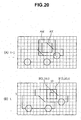
- FIG. 20 are illustrations of object maps according to the fourth embodiment of the present invention.
- the accuracy of object boundary is increased if a block size is reduced.
- the size of a block B' (i, j) used to determine the motion vector of the block B(i, j) is set to be larger than the size of the block B(i, j).
- the block B'(i, j) is concentric with the block B(i, j), and the block B(i, j) is included in the block B'(i, j).
- a block B'(t: 3, 10) is used to obtain the motion vector of a block B(t: 3, 10).
- the texture correlation between an image of the block B'(t: 3, 10) and an image of a corresponding block-size region AX at time (t - 1) is calculated for every block-size region AX moved pixel-by-pixel within a predetermined range AM.
- each block is compared with a corresponding block of the background picture to determine whether or not an object is present in the block.
- the camera shaking cannot be reflected in the background picture since the background picture is generated on the basis of pictures captured for the past, for example, 10 minutes.
- a background image is also regarded as an object in generating an object map.
- the object map generation method is same as that of any one of the first to fourth embodiments, except that it does not determine whether or not an object is present in a block on the basis of comparison with the background picture. Since a background image is also regarded as an object, block matching is performed for each block to assign an identification ID and determine a motion vector MV for each block.
- a motion vector MV which minimizes the value of the estimation function UD of Equation (2), is determined for each block at time t. However, motion vectors MV are not determined for blocks unsuitable for determining motion vectors.
- That process is performed for a picture as shown in FIG. 21(A) to obtain an object map of motion vectors as shown in FIG. 21(B) .
- dotted lines denote boundary between blocks, and dots denote motion vectors of zero.
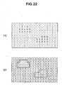
- a motion vector MV which minimizes the value of the estimation function UV of Equation (5), is obtained for each of the blocks unsuitable for determining motion vectors.
- This process makes an object map of motion vectors as shown in FIG. 22(A) .
- steps S12 to S15 is same as that of the second embodiment.
- step S12 makes an object map of IDs as shown in FIG. 22(B) .
- This method eliminates the need to use a special background picture, and also makes it possible to recognize a background picture even when the camera shakes. In addition, there is no need to set an entrance slit on the picture. Furthermore, the need to use exit slits can be eliminated by deleting the ID of an object when the object has exited the frame of a captured picture.
- a picture is divided-into blocks, and an object identification ID and an object motion vector MV are determined for each block, so that it is not possible to track a portion (for example, a block-size region) of a moving object, which is unrelated to boundaries between blocks.
- a picture is divided into blocks and an object identification ID and an object motion vector MV are determined for each block, and a portion of a moving object, which is unrelated to boundaries between the blocks, is also tracked.
- object maps OM(t) to OM(t - 5), which respectively correspond to time-series pictures at times "t” to "t - 5", have been stored in the object map storage section 26 of FIG. 2 .
- time "t” is replaced with time "t - 1", i.e., object maps OM(t) to OM(t - 5) becomes object maps OM(t - 1) to OM(t - 6), respectively.
- the oldest object map OM(t - 6) is updated to a new object map OM(t).
- the moving object tracking section 27 of FIG. 2 performs tracking of a portion of a moving object in the following manner.
- MV(t) is the motion vector of a region of interest A(t) on the object map OM(t). Dotted lines in FIG. 24(A) denote boundaries between blocks. In this example, the region of interest A(t) coincides with one block.
- a region of interest A(t - 1) on the object map OM(t - 1) is determined with moving the region of interest A(t) by -MV(t).
- a motion vector MV(t - 1) of the region of interest A(t - 1) is calculated through the use of following weighted averaging.
- MV ⁇ t - 1 MV ⁇ 1 • S ⁇ 1 + MV ⁇ 2 • S ⁇ 2 + MV ⁇ 3 • S ⁇ 3 + MV ⁇ 4 • S ⁇ 4 / S ⁇ 1 + S ⁇ 2 + S ⁇ 4
- MV1" to "MV4" denote the motion vectors of first to fourth blocks overlapping with the region of interest A(t - 1)
- S1" to "S4" denote the number of pixels of respective portions of the first to fourth blocks, which overlap with the region of interest A(t - 1).
- a region of interest A(t - 2) on the object map OM(t - 2) is obtained by moving the region of interest A(t - 1) by -MV(t - 1).
- a motion vector MV(t - 2) of the region of interest A(t - 2) is calculated in the same manner as described above.
- the sixth embodiment it is possible to track a region of interest which is a portion of a moving object, and thereby, for example, it is possible to analyze or classify a movement pattern of the region of interest or to judge it as a specific movement pattern. It is also possible to analyze or classify a movement pattern of the relative positions of a plurality of regions of interest or to judge it as a specific movement pattern.
- the motion vector of the region of interest is calculated through the use of weighted averaging as described above.
- the size of the region of interest may be smaller or larger than the block size.
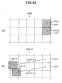
- regions of interest Ai(t - 5) and Aj(t - 5) on the object map OM(t - 5) are determined with using the method of the above sixth embodiment.
- a motion vector from the center of the region Ai(t 5) to the center of the region Ai(t) is obtained as a fast-forward motion vector MVi(t - 5, t).
- a motion vector from the center of the region Aj(t - 5) to the center of the region Aj(t) is obtained as a fast-forward motion vector MVj(t - 5, t).
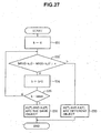
- FIG. 27 is a flow chart of a method of recognizing the boundary between moving objects in accordance with an eighth embodiment of the present invention.
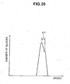
- the histogram is not made, but instead, the value "k” is changed from “0" to "kmax" for the two regions of interest of FIG. 25(A) in the following manner.
- the "kmax” is equal to, for example, "5" in the case of 10 frames/sec.
- the value "k" is automatically determined without making the histogram.
Landscapes
- Engineering & Computer Science (AREA)
- Multimedia (AREA)
- Physics & Mathematics (AREA)
- General Physics & Mathematics (AREA)
- Theoretical Computer Science (AREA)
- Computer Vision & Pattern Recognition (AREA)
- Image Analysis (AREA)
- Closed-Circuit Television Systems (AREA)
Description
- The present invention relates to a method and apparatus for tracking moving objects (i.e., movable things such as cars, bicycles, and animals) in pictures by processing time-series pictures to-track the moving objects therein.
- Early detection of a traffic accident not only enhances a success rate in life saving by fast rescue operation, but also alleviates accident-related traffic congestion by speedup of the police inspection at the site. Therefore, various types of automation in recognition of traffic accident are expected. In order to achieve a high recognition rate of traffic accidents, it is necessary to correctly track moving objects by processing pictures captured by a camera.
- "Occlusion robust and illumination invariant vehicle tracking for acquiring detailed statistics from traffic images" by KAMIJO S ET AL discloses a method of vehicle tracking based on "the Spatio-Temporal Markov Random Field model(S-T MRF) for segmentation of Spatio-Temporal images. This S-T MRF model optimizes the segmentation boundaries of occluded vehicles and their motion vectors simultaneously by referring to textures and segment labelling correlations along the temporal axis as well as the spatial axis".
-
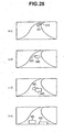
FIG. 28 schematically illustrates pictures at times t = 1 to 4 captured by a camera disposed above a halfway line of an expressway. - Since vehicles frequently overlap with each other in the captured pictures, it is difficult to track each vehicle by image processing. To overcome this problem, there is a need to dispose a plurality of cameras along the road and then to synthetically process all pictures captured by the cameras.
- However, the necessity to install a plurality of cameras and image processors increases costs. In addition, the necessity to associate and synthetically process pictures captured by the cameras makes the processing complicated.
- To overcome these problems, the present inventors have disclosed a method of tracking moving objects in pictures backward in time in the following manner (Japanese Patent Application Publication No.
2002-133421 - Time-series pictures at times t = 1 to 4 are temporarily stored. Starting-from time t = 4, vehicles M1 and M2 are identified, and motion vectors of the vehicles M1 and M2 are determined. Images of the vehicles M1 and M2 in the picture at time t = 4 are moved with the determined motion vectors to estimate a corresponding picture at t = 3 in which the vehicles M1 and M2 are identified. Based on the correlation between the estimated picture and the actual picture at t = 3, the vehicles M1 and M2 are identified in the picture at t = 3.
- Next, the same process is performed for the pictures at t = 3 and t = 2, so that the vehicles M1 and M2 are identified in the picture at t = 2. Then, the same process is performed for the pictures at t = 2 and t = 1, so that the vehicles M1 and M2 are identified in the picture at t = 1.
- This method makes it possible to track vehicles M1 and M2 using a single camera.
- However, in actuality, since pictures are processed at a rate of, for example, 12 frames/sec, there are disadvantages in that a large storage capacity is required for the time-series pictures, and the processing time is also increased.
- In addition, if the size of each image-block is reduced to improve the accuracy of recognition of the boundary of moving object, there arises a problem that it is difficult to determine motion vectors with block matching.
- In the above Japanese Patent Application Publication No.
2002-133421 - The background picture must be updated since it varies with time. Regarding all the pictures captured for the past 10 minutes, for example, a histogram of the pixel values of a corresponding pixel position is made for each pixel position, and a picture, each pixel value of which is equal to the most frequent pixel value (i.e., mode) of the corresponding histogram, is defined as a background picture.
- Taking these problems into consideration, it is an object of the present invention to provide a method and apparatus for tracking moving objects in pictures, which makes it possible to track moving objects with a smaller number of temporarily stored time-series pictures.
- It is another object of the present invention to provide a method and apparatus for tracking moving objects in pictures, which makes it possible to improve the accuracy of boundary recognition of moving objects without difficulty in determining motion vectors.
- In one aspect of the present invention, there is provided a method of tracking moving objects in time-series pictures with processing the pictures according to
claim 1. - According to another aspect of the invention there is provided an apparatus for tracking moving objects in time-series pictures according to
claim 2. Other aspects, objects, and the advantages of the present invention will become apparent from the following description. -
-
FIG. 1 is a schematic diagram illustrating an intersection and a moving object tracking apparatus according to a first embodiment of the present invention, which is placed at the intersection; -
FIG. 2 is a functional block diagram of the moving object tracking apparatus ofFIG. 1 ; -
FIG. 3 is a schematic diagram illustrating slits defined at four entrances and four exits of the intersection and IDs of moving objects assigned to blocks, in a frame picture; -
FIGS. 4(A) and 4(B) are schematic diagrams illustrating a picture at time (t-1) and a picture at time t, respectively, with block boundary lines; -
FIGS. 5(A) and 5(B) are schematic diagrams illustrating a picture at time (t-1) and a picture at time t, respectively, with pixel boundary lines; -
FIGS. 6(A) and 6(B) are schematic diagrams illustrating a picture at time (t-1) and a picture at time t, respectively, with motion vectors assigned to blocks; -
FIGS. 7(A) and 7(B) are schematic diagrams illustrating an object map at time (t-1) and an object map at time t, respectively, with motion vectors and object boundaries; -
FIG. 8 is a flow chart showing a method of estimating motion vectors which have not been determined; -
FIGS. 9(A) and 9(B) are schematic diagrams illustrating object maps for explaining the procedure ofFIG. 8 , with motion vectors and object boundaries; -
FIGS. 10 (A) to 10 (C) are schematic diagrams illustrating object maps for explaining the procedure ofFIG. 8 , with motion vectors and object boundaries; -
FIG. 11 is a flow chart showing a method of making an object map in accordance with a second embodiment of the present invention; -
FIGS. 12(A) and 12(B) are schematic diagrams for illustrating space-time texture correlation; -
FIGS. 13(A) and 13(B) are schematic diagrams for illustrating spatial ID correlation; -
FIGS. 14 (A) and 14 (B) are schematic diagrams for illustrating spatial motion vector correlation; -
FIGS. 15(A) and 15(B) are views, showing experimental results of the second embodiment of the present invention, of a captured picture of an intersection and of a corresponding object map of IDs, respectively; -
FIGS. 16(A) and 16(B) are views, showing experimental results of the second embodiment of the present invention, of a picture of an expressway captured at a low camera angle, and of a corresponding object map of IDs, respectively; -
FIGS. 17(A) and 17(B) are views, showing experimental results of the second embodiment of the present invention, of a captured picture of a crosswalk, and of a picture made by overlapping the captured crosswalk picture with a mesh of ID-assigned portions of a corresponding object map, respectively; -
FIG. 18 is a flow chart showing a method of determining whether or not object boundaries, through which a cluster is divided into objects, are established, according to a third embodiment of the present invention; -
FIGS. 19(A) to 19(C) are schematic diagrams for illustrating the procedure ofFIG. 18 ; -
FIGS. 20(A) and 20(B) are schematic diagrams, for illustrating block matching according to a fourth embodiment of the present invention, and showing a picture at time (t-1) and a picture at time t, respectively, with block boundary lines; -
FIGS. 21(A) and 21(B) are schematic diagrams, for illustrating a fifth embodiment of the present invention, of a captured picture and a corresponding object map of motion vectors obtained at a first step, respectively; -
FIGS. 22(A) and 22(B) are schematic diagrams, for illustrating the fifth embodiment of the present invention, showing an object map of motion vectors obtained at a second step and a corresponding object map of IDs, respectively; -
FIG. 23 is a schematic diagram illustrating time-series object maps used in a method of tracking a region of interest according to a sixth embodiment of the present invention; -
FIGS. 24(A) to 24(c) are schematic diagrams for illustrating how a region of interest is tracked backward in time according to the sixth embodiment of the present invention; -
FIGS. 25 (A) and 25 (B) are schematic diagrams for illustrating a method of recognizing object boundaries according to a seventh embodiment of the present invention; -
FIG. 26 is a schematic diagram illustrating a histogram of the absolute values of motion vectors for a single cluster; -
FIG. 27 is a flow chart showing a method of recognizing object boundaries according to an eighth embodiment of the present invention; and -
FIG. 28 is a schematic diagram illustrating time-series pictures captured by a camera disposed above a halfway line of an expressway. - Referring now to the drawings, wherein like reference characters designate like or corresponding portions throughout several views, preferred embodiments of the present invention will be described.
-
FIG. 1 is a schematic diagram showing an intersection and a moving object tracking apparatus according to a first embodiment of the present invention, which is placed at the intersection. - This apparatus includes an
electronic camera 10 for capturing the intersection to output the captured picture signal, and a movingobject tracking apparatus 20 for processing the captured pictures to track moving objects in the pictures. -
FIG. 2 is a functional block diagram of the movingobject tracking apparatus 20. Elements of the movingobject tracking apparatus 20, other than a memory thereof, can be implemented using computer software, a dedicated hardware, or a combination of both. - Time-series pictures shot by the
electronic camera 10 are stored in animage memory 21 at a rate of, for example, 12 frames/sec, in which the oldest frame picture is replaced with a new frame picture. - An
image converter 22 copies each of the frame pictures stored in theimage memory 21 into aframe buffer memory 23, and uses the data of the copied frame picture to convert the corresponding frame picture in theimage memory 21 to a spatial differential frame picture. This conversion has two steps. - Letting "G(i, j)" be a pixel value (brightness value) at the i-th row and j-th column of the original frame picture, then a pixel value H(i, j) at the i-th row and j-th column, which is obtained through the conversion in the first step, is expressed by the following equation.

where "Σneighborpixels" denotes a sum over di = -c to c and dj = -c to c with c being a natural number. For example, when c = 1, "Σneighborpixels" denotes a sum over 8 pixels neighboring to a pixel at the i-th row and j-th column. If the luminance varies, a pixel value G(i, j) and pixel values "G(i+di, j+dj)" in the neighborhood vary in like way. Therefore, the pixel value H(i, j) is not affected by variations in the luminance. - Generally, the larger the pixel value, the larger the absolute value of the difference between the pixel value and its neighboring pixel value. In order to increase the success rate of tracking moving objects, even if the pixel value is small and thus the difference is small, it is desired to obtain edge information almost equivalent to edge information obtained when the pixel value is large and thus the difference is large. Thus, the pixel value H(i, j) is normalized as follows:

where "Gi,j,max" denotes the maximum of the original pixel values used in the calculation of H(i, j). For example, when c = 1, the value "Gi,j,max" is the maximum of the pixel values of 3×3 neighboring pixels including the pixel of the i-th row and j-th column at the center. "Gmax" denotes the maximum allowable value of the pixel value G(i, j). For example, when the pixel value is expressed in 8 bits, the value "Gmax" is equal to 255. In the following description, it is assumed that c = 1 and Gmax = 255. - The maximum allowable value of H(i, j) varies depending on moving objects. For example, if G(i, j) = Gmax and all the 8 neighboring pixels have a pixel value of "0", then H(i, j) = 8Gmax and H(i, j) cannot be expressed in 8 bits.
- On the other hand, histograms of the values of H(i, j) for the edge portions of moving objects have showed that most values of H in the edge portions are in the range of 50 to 110. That is, as the value of H is larger than about 110, the amount of edge information for the tracking of moving object is smaller, and thus it becomes less important.
- Accordingly, it is desired to suppress portions having a high value of H in order to reduce the bit length of the converted pixel value and thereby attain a high image processing speed. Thus, in the second stage, it is performed to convert the pixel value "H(i, j)" to a pixel value "I(i, j)" with the following equation having a sigmoid function.

- The sigmoid function has a good linearity for values of H around α. Therefore, the value α is set to the most frequent value (for example, 80) in the- frequency distribution of the values of H that has edge information.
- The
image converter 22 converts, on the basis of the above equations (2) and (3), pictures having pixel values G(i, j) to spatial differential frame pictures having pixel values I(i, j), which are then stored in theimage memory 21. - A
background picture generator 24, an ID generation/deletion section 25, and a movingobject tracking section 27 perform processing on the basis of the spatial differential frame pictures stored in theimage memory 21. Hereinafter, the spatial differential frame picture is simply referred to as a frame picture. - The
background picture generator 24 includes storage and processing sections. Regarding all the pictures captured for the past 10 minutes, for example, the processing section accesses theimage memory 21 to produce a histogram of the pixel values of a corresponding pixel position for each pixel position, defines a picture, each pixel value of which is equal to the most frequent pixel value (i.e., mode) of the corresponding histogram, as a background picture with no moving object therein, and then stores the background picture in the storage section. This processing is repeated periodically to update the background picture. - As shown in
FIG. 3 , in the ID generation/deletion section 25, there are set the data of positions and sizes of slits EN1 to EN4 disposed at 4 entrances of the intersection in a frame picture and the data of positions and sizes of slits EX1 to EX4 disposed at 4 exits of the intersection. The ID generation/deletion section 25 reads data of images inside the entrance slits EN1 to EN4 from theimage memory 21 to determine whether or not a moving object exists in each block in each entrance slit. Squares in meshes ofFIG. 3 represent respective blocks, each block has a size of, for example, 8 x 8 pixels, and one frame is divided into 60 x 80 blocks if one frame is composed of 480 x 640 pixels. Whether or not a moving object exists in a block is determined on the basis of whether or not the sum of the absolute values, each of which is a difference between a pixel values in the block and a pixel value of the corresponding pixel of the background picture, is greater than a predetermined value. The determination is performed also in the movingobject tracking section 27. - The ID generation/
deletion section 25 assigns a new object identification (ID) to a block when it is determined that a moving object exists in the block. When it is determined that a moving object exists in a block adjacent to another block to which an ID has been assigned, the ID generation/deletion section 25 assigns the same ID as that of the assigned adjacent block. This block to which an ID has been assigned may be one adjacent to an entrance slit. For example inFIG. 3 , an ID of "1" is assigned to each block in the entrance slit EN1. - The ID assignment is performed for corresponding blocks in an object
map storage section 26. In the above example, the objectmap storage section 26 stores an object map having 60 x 80 blocks. For each block, provided is the block information including; a flag indicating whether or not an ID has been assigned to the block; and an ID number and a block motion vector described later when the ID has been assigned. An ID value of "0" may be used to indicate that no 10 has been assigned, without using the flag. Further, the most significant bit of an ID may be used as the flag. - For a cluster having passed an entrance slit, the moving
object tracking section 27 performs tracking with assigning the same ID to blocks in the moving direction side and deleting the ID of blocks in the reverse moving direction side. The movingobject tracking section 27 performs this tracking for each cluster until inside an exit slit. - The ID generation/
deletion section 25 further checks whether or not an ID is assigned to any block in the exit slits EX1 to EX4 on the basis of information in the objectmap storage section 26, and if an ID has been assigned to blocks in an exit slit, the ID generation/deletion section 25 deletes the ID assigned to the blocks when the cluster having the ID has passed through the exit slit. For example inFIG. 3 , when a transition is made from a state where an ID of "3" is assigned to blocks in the exit slit EX1 to a state where no ID is assigned thereto, the ID "3" is deleted. The deleted ID can be used as the next ID to be generated. - The moving
object tracking section 27 generates an object map at time t in thestorage section 26 on the basis of an object map at time (t - 1) stored in the objectmap storage section 26, and frame pictures at time (t - 1) and time t which are stored in theimage memory 21. This procedure will now be described. - Each of
FIGS. 4 to 7 illustrate a picture at time (t-1) and a picture at time t. Dotted lines inFIGS. 4 ,6 and7 denote boundary lines between blocks, and dotted lines inFIG. 5 are boundary lines between pixels. - "B(i, j)" denotes a block at the i-th row and j-th column, and "B(t: i, j)" denotes a block at the i-th row and j-th column at time t. Assume that a motion vector of a block B(t-1: 1, 4) is "MV". let us find a block at time t that best corresponds to a region to which the block B(t-1: 1, 4) is moved by the motion vector "MV". This block at time t is "B(t: 1, 5)" in the case of
FIG. 4 (B) . As shown inFIG. 5 , the correlation between an image of the block B(t: 1, 5) and an image of a block-size region AX at time (t-1) is calculated for every block-size region AX moved pixel-by-pixel within a predetermined range AM (block matching). - The range AM is set to be larger than the block size, and for example, one side of the range AM is 1.5 times larger than the number of pixels of corresponding one side of the block. The center of the range AM is a pixel located at a position to which the center of the block B(t: 1, 5) is moved by approximately -MV.
- The correlation is, for example, a space-time texture correlation. Assume that this-correlation increases as an evaluation value UD, which is the sum of the absolute values of the differences between pixel values of the block B(t: 1, 5) and corresponding pixel values of the region AX, decreases.
- A region AX in the range AM, which provides the largest correlation, is obtained, and a vector starting at the center thereof and ending at the center of the block B(1, 5) is determined to be a motion vector of the block B(t: 1, 5). The same ID of a block at time (t-1) nearest to the largest-correlation region AX is assigned as that of the block B(t: 1, 5).
- The moving
object tracking section 27 assigns the same ID to adjacent blocks if the absolute value of the difference between motion vectors of the adjacent blocks are less than a predetermined value. This allows a cluster to be divided into a plurality of objects (moving objects) having different IDs. InFIG. 6 , a bold line indicates the boundary between objects. - Although images of moving objects are not present on the object map, the moving objects are schematically drawn on the object map in
FIG. 6 for better understanding.FIG. 7 , which corresponds toFIG. 6 , illustrates a object map in which boundaries of the objects are shown by bold lines. - For example, assume that after one cluster is detected at the entrance slit EN1 of
FIG. 3 , which is not divided into a plurality of objects, the cluster is divided into a plurality of objects at time t1 in the same manner as described above. In this case, the cluster is divided into a plurality of objects in object maps at times previous to the time t1 by obtaining object maps with reverse tracking in time from time t1 in the same manner as forward tracking in time. Thereby it is possible to divide and recognize objects, which cannot be divided, and thus to track the objects individually. - In the above Japanese Patent Application Publication No.
2002-133421 FIG. 28 . This reduces the required storage capacity of theimage memory 21, and also decreases the amount of image processing, thereby reducing the load on the CPU. - The above description has been given for the case where the motion vectors of the blocks in a cluster can be determined. However, if there are blocks whose motion vectors are not determined as shown in
FIG. 9(A) , there is a location of a block in which it is not obvious which object the block belongs to. If the pixels in a block belonging to a certain moving object have almost the same color, it is not possible to determine the motion vector of the block through the use of the above block matching. For example, a picture (a spatial differential frame picture) is converted into a binary picture, and if the number of pixels having a pixel value "1" in a block is less than a predetermined value, the block is determined to be a block unsuitable for determining the motion vector through the use of the above method. - The motion vector of such a block is estimated in a method illustrated in
FIG. 8 . - (S1) If there is a block B(i, j) whose motion vector has not been determined, then the procedure goes to step S2, else the procedure for estimating motion vectors which have not been determined is terminated.
- (S2) Determined motion vectors MV1 to MVn of blocks from among 8 blocks surrounding the block B(i, j), whose motion vector is not determined, are picked up.
- (S3) If any determined motion vector is present at step S2, then the procedure goes to step S4, else it goes to step S6.
- (S4) The determined motion vectors MV1 to MVn are classified into groups of motion vectors such that the absolute value of a difference between any two motion vectors in the same group is less than a predetermined value.
- (S5) The motion vector of the B(i, j) is estimated to be equal to the average of the motion vectors of one of the classified groups, which has the largest number of motion vectors. If there are a plurality of groups having the largest number of motion vectors, the motion vector of the B(i, j) is estimated to be equal to the average of the motion vectors of any one of the plurality of groups. Then the procedure returns to step S1.
- Note that since motion vectors of the same group are approximately equal to each other, the motion vector of the B(i, j) may also be estimated to be equal to any one of the motion vectors of the same group.
- (S6) The motion vectors estimated at step S5 are regarded as determined motion vectors. Then, the procedure returns to step S1.
- Motion vectors which have not been determined, can be estimated uniquely in this manner.
- Next, examples will be explained. In
FIG. 9(A) , a motion vector of a block B(i, j) at the i-th row and j-th column is denoted by MV(i, j). InFIG. 9(A) , motion vectors of blocks B(2, 2), B(2, 4) and B(3, 3) are undetermined. Motion vectors of blocks surrounding the block B(2, 2) are divided into a group of motion vectors MV(2, 1), MV(3, 1), MV(3, 2) and MV(2, 3), and a group of motion vectors MV(1,2) and MV(1, 3). Therefore, the former group is selected, and estimation is performed as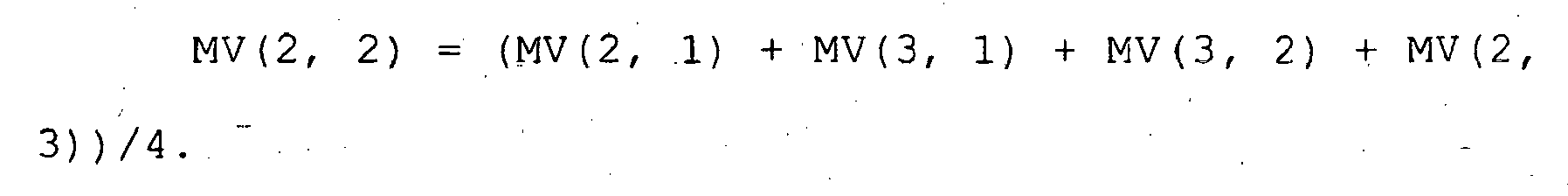
- Motion vectors of blocks surrounding the block B(2, 4) are divided into a group of motion vectors MV(2, 3), MV(3, 4), and MV (3, 5), and a group of motion vectors (1, 3), MV (1, 4), MV (1, 5) and (2, 5). Therefore, the latter group is selected, and-estimation is performed as

- Motion vectors of blocks surrounding the block B(3, 3) constitute one group of motion vectors MV(2, 3), MV(3, 2), MV (4, 2), MV(4, 4), and MV(3, 4). Therefore, the motion vector MV(3, 3) of the block B(3, 3) is estimated as

- In this manner, an object map as shown in
FIG. 9(B) is made. InFIG. 9(B) , the boundaries of the objects are indicated by bold lines. - Even when there are a large number of undetermined motion vectors as shown in
FIG. 10(A) , the motion vectors can be estimated uniquely as shown inFIG. 10(B) by repeating steps S1 to S5 until the determination of step S3 is negative. Then, the estimated motion vectors are regarded as determined motion vectors at step S6, and then steps S1 to S5 are performed once again, so that the motion vector of the block B(3, 4) is uniquely estimated as shown inFIG. 10(C) . Then, the same ID is assigned to any adjacent blocks if the absolute value of the difference between the adjacent motion vectors is less than a predetermined value. This allows one cluster to be divided into a plurality of objects having different IDs. - Note that the moving
object tracking section 27 stores the time-series object maps stored in the objectmap storage section 26, as a tracking result, in a hard disk not shown. - In the first, embodiment, the unknown motion vector of a block is estimated on the basis only of motion vectors of blocks surrounding the block, so that the accuracy of estimation of the ID and motion vector of the block is reduced if there are a large number of undetermined motion vectors.
- To increase the accuracy, the second embodiment of the present invention determines the IDs and motion vectors of all blocks at the same time, on the basis of values of an estimation function, which is described below. In the second embodiment, in the same manner as in the first embodiment, the moving
object tracking section 27 ofFIG. 2 makes and stores an object map at time t in the objectmap storage section 26, on the basis of both an object map at time (t-1) stored in the objectmap storage section 26 and frame pictures at times (t-1) and t stored in theimage memory 21. - Firstly, a description will be given of an estimation function U(i, j) of any block B(t: i, j) including a portion of a moving object. The estimation function U(i, j) is expressed as a linear combination of four sub-estimation functions as follows.

- Here, "a", "b", "c" and "f" are constants, which are determined by trial and error.
- In the following description, one block is assumed to be composed of m x m pixels, "G(t: g, h)" denotes a pixel value of a pixel at the g-th row and h-th column at time t, and "(MVX, MVY)" denotes an estimated motion vector MV of a block B(t: i, j). It is also assumed that i≥0, and j≥0.
- The sub-estimation function UD represents a time-space texture correlation, which is the same as described in the first embodiment and is expressed by the following equation.

where "Σ" denotes a sum over x = 0 to m - 1 and y = 0 to m - 1. - In
FIG. 12 , doted lines denote boundaries between blocks, and a hatched portion indicates a moving object.FIG. 12(B) shows an estimated motion vector "MV" of a block of interest B (t : 1, 2), andFIG. 12 (A) shows a region "AX" to which a block B(t: 1, 2) is moved by -MV. In this case, an estimation function UD (1, 2, MV) of an image of the block B(t: 1, 2) and an image of the region AX is calculated. If MV is changed, the value of UD is also changed, and the smaller the value of UD, the larger the texture correlation between the image of the block B(t: 1, 2) and the image of the region AX. A motion vector MV, which provides the smallest value of UD, is the most probable motion vector. Since there are limitations on the speed of moving objects, the minimum value of UD is calculated with moving the region AX pixel-by-pixel within a specific range from the center of the block of interest B(t: 1, 2), for example, within a range of ±25 pixels in the vertical direction and ±25 pixels in the horizontal direction. This specific range may also be a range "AM" estimated with using the motion vector at time (t - 1) as described above in the first embodiment. -
FIGS. 13(A) and 13(B) correspond toFIGS. 12(A) and 12(B) , respectively, and hatched portions therein indicate blocks estimated that a moving object is present. - When the ID of the block of interest-B(t: 1, 2) is estimated to be "ID1", let "M" be the number of pixels of ID = "ID1" included in the region AX. In the case of
FIG. 13(A) , the number of pixels of the hatched portion inside the region is "M". However, the value "M" is zero if the estimated ID of the block of interest B(t: 1, 2) quite differs from IDs inside the region AX. The maximum value of M is m2. - The sub-estimation function UM indicates a space-time ID correlation and is expressed by the following equation.

- The smaller the value of UM, the larger the space-time ID correlation.
- It is possible to determine the ID and MV of the block of interest B(t: i, j) at the same time by obtaining the minimum value of "aUD + bUM" with moving the region AX pixel-by-pixel within the predetermined range from the center of the block of interest B(t: i, j).
- In
FIG. 13(B) , when the ID of the block of interest B(t: 1, 2) is estimated to be "ID1", let "N" be the number of blocks with ID being equal to "ID1" within 8 blocks which surround the block of interest, i.e., B(t: 0, 1), B(t: 0, 2), B(t: 0, 3), B(t: 1, 3), B(t: 2, 3), B(t: 2, 2), B(t: 2, 1), and B(t: 1, 1). If all the blocks of the hatched portion of theFIG. 13(B) have the same ID, the value "N" of the block of interest B(t: 1, 2) is 5. - The sub-estimation function UN indicates a spatial ID correlation and is expressed by the following equation.

- The smaller the value of UN, the larger the spatial ID correlation.
- It is possible to determine the ID and MV of the block of interest B(t: i, j) at the same time by obtaining the minimum value of "aUD + bUM + cUN" with moving the region AX pixel-by-pixel within the predetermined range from the center of the block of interest B(t: i, j).
- However, if a plurality of regions, which are obtained by moving the region AX, have the same texture as the block of interest, the motion vector MV cannot be determined. This motion vector MV can be estimated to be almost the same as the motion vector MV of a block which is near the block of interest and also has the same ID as the block of interest. Therefore, a sub-estimation function UV, which indicates a spatial MV correlation, is defined as follows.

- Here, "MV" denotes the estimated motion vector of the block of interest B(t: i, j) described above item (1), "MVneighbor" denotes motion vectors of blocks having the same ID as the estimated ID of the block of interest B(t: i, j), within 8 blocks surrounding the block of interest B(t: i, j), "Σ" denotes a sum over blocks having the same ID, and "L" denotes the number of blocks having the same ID.
- In the case of
FIG. 14(A) , assuming that the hatched blocks have the same ID, the following holds.
- If the region AX at time (t - 1) is as shown in
FIG. 14(B) , the value of UV(1, 2) is large, so that the reliability of the estimated motion vector MV is low. The smaller the value of UV, the larger the spatial MV correlation. - It is possible to determine the ID and MV of the block of interest B(t: i, j) at the same time by minimizing the minimum value of the estimation function U of the above Equation (1) with moving the region AX within the predetermined range from the center of the block of interest B(t: i, j).
- Note that "MVneighbor" may be motion vectors of blocks surrounding the block of interest B(t: i, j), for example, 4 blocks on the left, right, top and bottom, one of the 8 blocks surrounding the block of interest B(t: i, j) (one round), or blocks having the same ID as the estimated ID of the block of interest B(t: i, j) within 24 blocks surrounding the block of interest B(t: i, j) (two rounds). "MVneighbor" may- be approximated by a corresponding motion vector at time (t - 1). That is, letting "B(t - 1, p, q)" be a block to which the center of a region, which is obtained by moving the block of interest B(t: i, j) by -MV, belongs, the motion vector may be a motion vector of a block having the same ID as the estimated motion vector of the block of interest B(t: i, j) within blocks near the block B(t - 1,p,q).
- Since both the sub-estimation functions UN and UV are associated with spatial correlation at time t, ideally, IDs and MVs of all the blocks at time t is determined at the same time by obtaining the minimum value of the estimation function U regarding all the blocks. Practically, the IDs and MVs are determined in accordance with the approximation method as shown in
FIG. 11 in order to reduce processing time and thus allow real-time processing. - (S11) A motion vector MV, which minimizes the value of the estimation function UD of the above equation (2), is determined for each block that includes a portion of a moving object at time t. There is a exception that motion vectors MV are not obtained for blocks unsuitable for determining motion vectors. Then, a motion vector MV, which minimizes the value of the estimation function UV of Equation (5), is obtained for each of the blocks unsuitable for determining motion vectors. In this case, the procedure of steps S1 to S3 and S6 of
FIG. 8 may be added to uniquely determine the motion vectors. - (S12) An ID is determined for each block having a motion vector MV in such a way that the value of the estimation function UM of Equation (3) is minimized. This motion vector MV, which is obtained at step S11, is fixed. For the first image to which no ID is assigned at time (t - 1), the same ID is assigned to adjacent blocks if the absolute value of the difference between motion vectors of the adjacent blocks are less than a predetermined value.
- (S13) The sum UT of the values of the estimation functions U for blocks, IDs and MVs of which have been determined, is calculated.
- (S14) The distribution of IDs and MVs is changed in order to obtain a distribution of IDs and MVs which makes the sum UT smaller.
- (S15) If it is determined that steps S13 and S14 have been repeated a predetermined number of times or if it is determined that the sum UT converges to a certain value, then the procedure is terminated, else it returns to step S15.
- In this manner, it is possible to obtain, in real-time, an ID and MV distribution that approximately minimizes the sum UT.
- For example, at step S14, the motion vector MV of one block is shifted pixel-by-pixel within a predetermined range, or the ID of one block is changed. Then, the procedure returns to step S13, and if the sum UT is larger than the previous one, the changed MV or ID is restored at step S14. If the sum UT is less than the previous one, like change is made to the next block. The predetermined range is, for example, +4 pixels in each direction of left, right, top and bottom of the block.
- If the MV or ID of one block is changed, the change will not affect the evaluation functions of all blocks. Therefore, it is also possible to approximately minimize the sum UTportion of the values of evaluation-functions U of only blocks affected by the change, without calculating the sum UT. In this case, it is possible to determine whether or not each block is affected by the change, by temporarily storing the value of the evaluation function U of each block and comparing the current value thereof with the previous one thereof.
- In addition, instead of repeating the procedure of steps S13 to S15, it is also possible to previously estimate a procedure for making the sum UT smaller, perform the estimated procedure to calculate the sum UT or UTportion, and then_adopt its object map if the value of the sum UT or UTportion is smaller than the value previous to the procedure, else adopt the previous object map. An example of the estimated procedure is spatial averaging of motion vectors on the basis of Equation (5). That is, since the value of Equation (5) can be minimized when "MV" in Equation (5) is set to be equal to "MMVneighbor/L", "MV" is set to be equal to "ΣMVneighbor/L" with using previously obtained "MVneighbor".
- Further, at step, S11, without determining the motion vectors for blocks unsuitable for determining motion vectors, the motion vector of each of the blocks unsuitable for determining motion vectors may be determined through the procedure of steps S13 to S15 or the alternative procedure as described above.
- The following are experimental results of the second embodiment.
- The constants "a", "b", "c" and "f" in Equation (1) were determined as "a = 32/100000", "b = 1/256", "c = 1/2", and "f = 1/4" by trial and error. The spatial averaging of motion vectors was performed as described above, instead of repeating the steps S13 to S15.
-
FIGS. 15(A) and 15(B) illustrate a captured picture of an intersection, and a corresponding object map of IDs, respectively. Bold lines therein indicate rectangular regions, each having the same ID. -
FIGS. 16(A) and 16(B) illustrate a picture of an expressway captured at a low camera-angle, and a corresponding object map of IDs, respectively. -
FIGS. 17 (A) and 17-(B) illustrate a captured picture of a crosswalk, and a picture made by overlapping the captured crosswalk picture with a mesh of ID-assigned portions of a corresponding object map, respectively. - Numbers assigned to rectangular regions in
FIGS. 16(A) and17(B) indicate object IDs. - Such crowding and overlapping moving objects could be tracked.
- If there are a large number of estimated motion vectors on both sides of the boundary between objects as shown in
FIG. 10(C) , and if the absolute value of the difference between motion vectors on both sides of the boundary is relatively small, the accuracy of the object boundary is low. In this case, the tracking accuracy is also low when objects are tracked backward in time. - This problem can be overcome by increasing the predetermined value in the rule that "the same ID is assigned to adjacent blocks if the absolute value of the difference between motion vectors MV of the adjacent blocks are less than the predetermined value". However, this causes a delay in the start time of the tracking backward in time..
- To overcome these problems, according to the third embodiment of the present invention, the start time of the tracking backward in time is determined by performing a method as shown in
FIG. 18 . In this method, the reliability of the object boundary is determined to be high if the correlations (space-time correlation of objects) between corresponding objects in temporally adjacent pictures within N consecutive pictures, for example, 3 consecutive pictures, are more than a predetermined value. - Assume that, for example, an object map at time (t - 1) has been made as shown in
FIG. 19(A) . - (S21) An initial value "0" is assigned to a counter CNT.
- (S22) An object map at time t is made through the method as described above in the first embodiment.
FIG. 19(B) illustrates the object map at time t. - (S23) If a plurality of objects are included in one cluster, then the procedure goes to step S24, else it goes to step S27.
- (S24) A space-time correlation of objects is calculated in regard to the object map at time t and the object map at time (t - 1).
- For example, an area A1 (a hatched figure in
FIG. 19(C) ) is determined by performing a logical AND operation between a figure, which is obtained by moving an object OBJ1 (t - 1) shown inFIG. 19(A) by an average motion vector of the object OBJ1 (t - 1), and a figure of a corresponding object OBJ1 (t) shown inFIG. 19(B) . An area A0 of the figure of the object OBJ1 (t - 1) is also calculated. Then, the ratio of the areas "A1/A0" is calculated as the correlation. The area A0 may be the area of the figure of the object OBJ1(t). - (S25) If the ratio A1/A0 is more than or equal to a predetermined value r0, then the procedure goes to step S26, else it goes to step S27.
- (S26) The counter CNT is incremented by one, and the procedure goes to step S28.
- (S27) The counter CNT is cleared to zero.
- (S28) If CNT < N - 1, then the procedure goes to step S29, else it goes to step S30.
- (S29) The next time "t + 1" is set as "t", and the procedure returns to step S21.
- (S30) The space-time correlation of the objects is determined to be high, and the objects are tracked backward in time from time "t".
-
FIG. 20 are illustrations of object maps according to the fourth embodiment of the present invention. - The accuracy of object boundary is increased if a block size is reduced. However, the smaller the block size is, the more difficult it is to determine the motion vector through the use of block matching.
- To overcome this problem, in the fourth embodiment of the present invention, for each block B(i, j) to which an ID and a motion vector MV are to be assigned, the size of a block B' (i, j) used to determine the motion vector of the block B(i, j) is set to be larger than the size of the block B(i, j). The block B'(i, j) is concentric with the block B(i, j), and the block B(i, j) is included in the block B'(i, j).
- For example in
FIG. 20 , a block B'(t: 3, 10) is used to obtain the motion vector of a block B(t: 3, 10). In like manner as in the case ofFIG. 5 , the texture correlation between an image of the block B'(t: 3, 10) and an image of a corresponding block-size region AX at time (t - 1) is calculated for every block-size region AX moved pixel-by-pixel within a predetermined range AM. - The other features of the fourth embodiment are the same as those of the first to third embodiments.
- In the above embodiments, it is necessary to specially handle the background picture since each block is compared with a corresponding block of the background picture to determine whether or not an object is present in the block. In addition, if the camera shakes, the camera shaking cannot be reflected in the background picture since the background picture is generated on the basis of pictures captured for the past, for example, 10 minutes.
- To overcome these problem, in the fifth embodiment of the present invention, a background image is also regarded as an object in generating an object map. The object map generation method is same as that of any one of the first to fourth embodiments, except that it does not determine whether or not an object is present in a block on the basis of comparison with the background picture. Since a background image is also regarded as an object, block matching is performed for each block to assign an identification ID and determine a motion vector MV for each block.
- Next, the procedure for making an object map at time t through the method of
FIG. 11 will be schematically described with reference toFIGS. 21 and22 . - (S11) A motion vector MV, which minimizes the value of the estimation function UD of Equation (2), is determined for each block at time t. However, motion vectors MV are not determined for blocks unsuitable for determining motion vectors.
- That process is performed for a picture as shown in
FIG. 21(A) to obtain an object map of motion vectors as shown inFIG. 21(B) . InFIG. 21(B) , dotted lines denote boundary between blocks, and dots denote motion vectors of zero. - Next, a motion vector MV, which minimizes the value of the estimation function UV of Equation (5), is obtained for each of the blocks unsuitable for determining motion vectors. This process makes an object map of motion vectors as shown in
FIG. 22(A) . - The procedure of steps S12 to S15 is same as that of the second embodiment.
- The process of step S12 makes an object map of IDs as shown in
FIG. 22(B) . - This method eliminates the need to use a special background picture, and also makes it possible to recognize a background picture even when the camera shakes. In addition, there is no need to set an entrance slit on the picture. Furthermore, the need to use exit slits can be eliminated by deleting the ID of an object when the object has exited the frame of a captured picture.
- In the above embodiments, a picture is divided-into blocks, and an object identification ID and an object motion vector MV are determined for each block, so that it is not possible to track a portion (for example, a block-size region) of a moving object, which is unrelated to boundaries between blocks.
- In the sixth embodiment of the present invention, a picture is divided into blocks and an object identification ID and an object motion vector MV are determined for each block, and a portion of a moving object, which is unrelated to boundaries between the blocks, is also tracked.
- As shown in
FIG. 23 , object maps OM(t) to OM(t - 5), which respectively correspond to time-series pictures at times "t" to "t - 5", have been stored in the objectmap storage section 26 ofFIG. 2 . - At the next time, time "t" is replaced with time "t - 1", i.e., object maps OM(t) to OM(t - 5) becomes object maps OM(t - 1) to OM(t - 6), respectively. In addition, the oldest object map OM(t - 6) is updated to a new object map OM(t).
- The moving
object tracking section 27 ofFIG. 2 performs tracking of a portion of a moving object in the following manner. - In
FIG. 24(A) , assume that "MV(t)" is the motion vector of a region of interest A(t) on the object map OM(t). Dotted lines inFIG. 24(A) denote boundaries between blocks. In this example, the region of interest A(t) coincides with one block. - As shown in
FIG. 24(B) , a region of interest A(t - 1) on the object map OM(t - 1) is determined with moving the region of interest A(t) by -MV(t). - A motion vector MV(t - 1) of the region of interest A(t - 1) is calculated through the use of following weighted averaging.

where "MV1" to "MV4" denote the motion vectors of first to fourth blocks overlapping with the region of interest A(t - 1), and "S1" to "S4" denote the number of pixels of respective portions of the first to fourth blocks, which overlap with the region of interest A(t - 1). - As shown in
FIG. 24(C) , a region of interest A(t - 2) on the object map OM(t - 2) is obtained by moving the region of interest A(t - 1) by -MV(t - 1). - A motion vector MV(t - 2) of the region of interest A(t - 2) is calculated in the same manner as described above.
- By repeating such movement of the region of interest and motion vector calculation thereof after the movement, it is possible to track the region of interest, independently of the boundaries of blocks. That is, for the region of interest A(t), it is possible to obtain corresponding regions of interest A(t - 1) to A(t - 5) at times (t - 1) to (t - 5).
- According to the sixth embodiment, it is possible to track a region of interest which is a portion of a moving object, and thereby, for example, it is possible to analyze or classify a movement pattern of the region of interest or to judge it as a specific movement pattern. It is also possible to analyze or classify a movement pattern of the relative positions of a plurality of regions of interest or to judge it as a specific movement pattern.
- Although the above example has been described for the case where the region of interest at time t coincides with one block, a case may be where the region of interest does not coincide with a block as shown in
FIG. 24(B) . In this case, the motion vector of the region of interest is calculated through the use of weighted averaging as described above. - In addition, although the above example has been described for the case where the region of interest is tracked backward in time, it is also possible to track the region of interest forward in time, starting from the region of interest A(t - 5) on the object map OM(t - 5), by moving the region of interest with the motion vector in the positive direction thereof. In this case, it is possible to track a region of interest by determining a corresponding region of interest A(t) each time a new object map OM(t) is obtained.
- The size of the region of interest may be smaller or larger than the block size.
- Next, an example where boundaries between objects are identified using the method-of the sixth embodiment will be described as a seventh embodiment of the present invention.
- In
FIG. 25(A) , assume that "MVi(t)" and "MVj(t)" are the motion vectors of adjacent regions of interest Ai(t) and Aj (t) on an object map OM(t), respectively. Even when the regions Ai(t) and Aj(t) are portions of different moving objects, it is not possible to recognize the regions as different moving objects if |MVi(t) - MVj(t)|) is relatively small. Particularly, this problem occurs when a plurality of moving objects located far away from the camera are seen to be overlapped. - Therefore, regions of interest Ai(t - 5) and Aj(t - 5) on the object map OM(t - 5) are determined with using the method of the above sixth embodiment. A motion vector from the center of the region Ai(t 5) to the center of the region Ai(t) is obtained as a fast-forward motion vector MVi(t - 5, t). In the same manner, a motion vector from the center of the region Aj(t - 5) to the center of the region Aj(t) is obtained as a fast-forward motion vector MVj(t - 5, t). If the value of |MVi(t - 5, t) - MVj(t - 5, t) I exceeds a predetermined value "ε", it is recognized that the boundary between the two regions of interest Ai(t) and Aj(t) is identified to a boundary between different moving objects.
- By performing such a process for all adjacent blocks in a cluster on the object map OM(t), it is possible to recognize a plurality of divided moving objects included in the cluster.
- In the above example, the case is described in which a value of "k" in |MVi(t - k, t) - MVj(t - k, t)|) is equal to 5. However, it is preferable to increase the value "k" as - - the relative speed of moving objects in the picture, which are seen to be overlapped, decreases.
- Thus, as shown in
FIG. 26 , a histogram of absolute values of motion vectors is made for a single cluster. If there are a plurality of peaks in the histogram, it is possible to estimate that a plurality of moving objects are included in the cluster. Letting "ΔV" be the distance between the peaks, the value "k" is determined as k = [αΔV], where "α" is a constant determined by trial and error, and "[]" designates to round off to the nearest integer. -
FIG. 27 is a flow chart of a method of recognizing the boundary between moving objects in accordance with an eighth embodiment of the present invention. - In this method, the histogram is not made, but instead, the value "k" is changed from "0" to "kmax" for the two regions of interest of
FIG. 25(A) in the following manner. The "kmax" is equal to, for example, "5" in the case of 10 frames/sec. - (S31) An initial values "0" is assigned to "k".
- (S32) If |MVi(t - k, t) - MVj(t - k, t)| > ε holds, then the procedure goes to step S33, else it goes to step S34.
- (S33) The boundary between the two regions of interest Ai(t) and Aj(t) is recognized as a boundary between different moving objects.
- (S34) The value "k" is incremented by one.
- (S35) If k > kmax holds, the procedure goes to step S36, else it returns to step S32.
- (S36) It is recognized that the two regions of interest Ai(t) and Aj(t) belong to the same moving object.
- The other features are same as those of the seventh embodiment.
- According to the eighth embodiment, the value "k" is automatically determined without making the histogram.
- Note that the present invention includes other various modifications.
- For example, although the above embodiments have been described for the case where moving objects are tracked by processing spatial differential, pictures, there may be configuration of tracking moving objects (or portions thereof) by processing various types of edge images or the original pictures according to the present invention.
Claims (2)
- A method of tracking moving objects in time-series pictures with processing the pictures, each picture being divided into blocks, each block consisting of a plurality of pixels, wherein in a case where an identification code of moving object is assigned in a unit of block, and a motion vector of moving object is determined in a unit of block, the method comprising the steps of:(a) for each of N (N>=2) consecutive pictures within the time-series pictures, assigning the same identification code to adjacent blocks if an absolute value of difference between motion vectors of the adjacent blocks is less than a predetermined value, thereby allowing different identification codes to be assigned to different moving objects overlapping in a picture;characterized in that it comprises:(b) judging whether or not: a first object consisting of a group of blocks assigned a first identification code and a second object consisting of a group of blocks assigned a second identification code are in contact with each other in each of the N consecutive pictures; and a correlation between the first objects in every temporally adjacent pictures in the N consecutive pictures is more than a predetermined value, wherein the correlation is equal to a ratio of an area of a logical AND between a figure obtained by moving one of the temporally adjacent first objects on the basis of an average motion vector of the one of the temporally adjacent first objects and the other of the temporally adjacent first objects to an area of the one or the other of the temporally adjacent first objects; and(c) tracking the first and second objects backward in time after the judgment of the step (b) is positive.
- An apparatus for tracking moving objects in time-series pictures, comprising:a storage device for storing the time-series pictures and a program; anda processor coupled to the storage device,wherein the program make the processor read and process the time-series pictures to track the moving objects in the pictures, and by the processing, each picture is divided into blocks, each block consisting of a plurality of pixels, an identification code of moving object is assigned in a unit of block, and a motion vector of moving object is determined in a unit of block, the program comprising the step of:(a) for each of N (N>=2) consecutive pictures within the time-series pictures assigning the same identification code to adjacent blocks if an absolute value of a difference between motion vectors of the adjacent blocks is less than a predetermined value, thereby allowing different identification codes to be assigned to different moving objects overlapping in a picture;characterized in that it comprises:(b) judging whether or not: a first object consisting of a group of blocks assigned a first identification code and a second object consisting of a group of blocks assigned a second identification code are in contact with each other in each of the N consecutive pictures; and a correlation between the first objects in every temporally adjacent pictures in the N consecutive pictures is more than a predetermined value; wherein the correlation is equal to a ratio of an area of a logical AND between a figure obtained by moving one of the temporally adjacent first objects on the basis of an average motion vector of the one of the temporally adjacent first objects and the other of the temporally adjacent first objects to an area of the one or the other of the temporally adjacent first objects; and(c) tracking the first and second objects backward in time after the judgment of the step (b) is positive.
Applications Claiming Priority (3)
| Application Number | Priority Date | Filing Date | Title |
|---|---|---|---|
| JP2002371047A JP4217876B2 (en) | 2002-12-20 | 2002-12-20 | Method and apparatus for tracking moving object in image |
| JP2002371047 | 2002-12-20 | ||
| PCT/JP2003/016058 WO2004057537A1 (en) | 2002-12-20 | 2003-12-15 | Method and device for tracing moving object in image |
Publications (3)
| Publication Number | Publication Date |
|---|---|
| EP1574992A1 EP1574992A1 (en) | 2005-09-14 |
| EP1574992A4 EP1574992A4 (en) | 2009-11-11 |
| EP1574992B1 true EP1574992B1 (en) | 2015-03-04 |
Family
ID=32677192
Family Applications (1)
| Application Number | Title | Priority Date | Filing Date |
|---|---|---|---|
| EP03778936.9A Expired - Lifetime EP1574992B1 (en) | 2002-12-20 | 2003-12-15 | Method and device for tracking moving objects in images |
Country Status (8)
| Country | Link |
|---|---|
| US (1) | US7929613B2 (en) |
| EP (1) | EP1574992B1 (en) |
| JP (1) | JP4217876B2 (en) |
| KR (2) | KR20050085842A (en) |
| CN (1) | CN100385462C (en) |
| AU (1) | AU2003289096A1 (en) |
| CA (1) | CA2505563A1 (en) |
| WO (1) | WO2004057537A1 (en) |
Families Citing this family (41)
| Publication number | Priority date | Publication date | Assignee | Title |
|---|---|---|---|---|
| JP4714872B2 (en) * | 2006-01-12 | 2011-06-29 | 国立大学法人 東京大学 | Method and apparatus for dividing moving object superimposed on image |
| JP4734568B2 (en) * | 2006-01-12 | 2011-07-27 | 国立大学法人 東京大学 | Method and apparatus for determining moving object measurement point on image |
| US8085849B1 (en) * | 2006-11-03 | 2011-12-27 | Keystream Corporation | Automated method and apparatus for estimating motion of an image segment using motion vectors from overlapping macroblocks |
| KR20080057500A (en) * | 2006-12-20 | 2008-06-25 | 재단법인 포항산업과학연구원 | Human motion tracking system and its method |
| JP2009053815A (en) * | 2007-08-24 | 2009-03-12 | Nikon Corp | Subject tracking program and subject tracking device |
| US20090097704A1 (en) * | 2007-10-10 | 2009-04-16 | Micron Technology, Inc. | On-chip camera system for multiple object tracking and identification |
| KR100921821B1 (en) | 2007-12-07 | 2009-10-16 | 영남대학교 산학협력단 | A method for constructing a characteristic space trajectory database and a method for identifying angular targets using the same |
| US8325976B1 (en) * | 2008-03-14 | 2012-12-04 | Verint Systems Ltd. | Systems and methods for adaptive bi-directional people counting |
| US9019381B2 (en) * | 2008-05-09 | 2015-04-28 | Intuvision Inc. | Video tracking systems and methods employing cognitive vision |
| JP4507129B2 (en) * | 2008-06-06 | 2010-07-21 | ソニー株式会社 | Tracking point detection apparatus and method, program, and recording medium |
| CN101615294B (en) * | 2008-06-26 | 2012-01-18 | 睿致科技股份有限公司 | A Method for Tracking Multiple Objects |
| KR100958379B1 (en) * | 2008-07-09 | 2010-05-17 | (주)지아트 | Multi-object tracking method, apparatus and storage medium |
| US8325227B2 (en) * | 2008-07-15 | 2012-12-04 | Aptina Imaging Corporation | Method and apparatus for low cost motion detection |
| US20100119109A1 (en) * | 2008-11-11 | 2010-05-13 | Electronics And Telecommunications Research Institute Of Daejeon | Multi-core multi-thread based kanade-lucas-tomasi feature tracking method and apparatus |
| CN101719278B (en) * | 2009-12-21 | 2012-01-04 | 西安电子科技大学 | Automatic tracking method for video microimage cells based on KHM algorithm |
| JP5561524B2 (en) * | 2010-03-19 | 2014-07-30 | ソニー株式会社 | Image processing apparatus and method, and program |
| JP5338978B2 (en) * | 2010-05-10 | 2013-11-13 | 富士通株式会社 | Image processing apparatus and image processing program |
| JP5459154B2 (en) * | 2010-09-15 | 2014-04-02 | トヨタ自動車株式会社 | Vehicle surrounding image display apparatus and method |
| JP5218861B2 (en) * | 2010-09-30 | 2013-06-26 | 株式会社Jvcケンウッド | Target tracking device and target tracking method |
| JP5828210B2 (en) * | 2010-10-19 | 2015-12-02 | ソニー株式会社 | Image processing apparatus and method, and program |
| US10018703B2 (en) * | 2012-09-13 | 2018-07-10 | Conduent Business Services, Llc | Method for stop sign law enforcement using motion vectors in video streams |
| WO2013077562A1 (en) * | 2011-11-24 | 2013-05-30 | 에스케이플래닛 주식회사 | Apparatus and method for setting feature points, and apparatus and method for object tracking using same |
| KR101939628B1 (en) | 2012-05-30 | 2019-01-17 | 삼성전자주식회사 | Method of detecting motion and motion detector |
| CN103678299B (en) * | 2012-08-30 | 2018-03-23 | 中兴通讯股份有限公司 | A kind of method and device of monitor video summary |
| US9311338B2 (en) * | 2013-08-26 | 2016-04-12 | Adobe Systems Incorporated | Method and apparatus for analyzing and associating behaviors to image content |
| KR102161212B1 (en) | 2013-11-25 | 2020-09-29 | 한화테크윈 주식회사 | System and method for motion detecting |
| US9598011B2 (en) * | 2014-01-09 | 2017-03-21 | Northrop Grumman Systems Corporation | Artificial vision system |
| US10290287B1 (en) * | 2014-07-01 | 2019-05-14 | Xilinx, Inc. | Visualizing operation of a memory controller |
| CN104539864B (en) * | 2014-12-23 | 2018-02-02 | 小米科技有限责任公司 | The method and apparatus for recording image |
| CN106296725B (en) * | 2015-06-12 | 2021-10-19 | 富泰华工业(深圳)有限公司 | Moving target real-time detection and tracking method and target detection device |
| CN105719315B (en) * | 2016-01-29 | 2019-01-22 | 深圳先进技术研究院 | Method for tracking objects in video images in a mobile terminal |
| JP6526589B2 (en) * | 2016-03-14 | 2019-06-05 | 株式会社東芝 | Image processing device and image processing program |
| KR102553598B1 (en) * | 2016-11-18 | 2023-07-10 | 삼성전자주식회사 | Image processing apparatus and controlling method thereof |
| US11405581B2 (en) * | 2017-12-26 | 2022-08-02 | Pixart Imaging Inc. | Motion detection methods and image sensor devices capable of generating ranking list of regions of interest and pre-recording monitoring images |
| JP7227969B2 (en) * | 2018-05-30 | 2023-02-22 | パナソニック インテレクチュアル プロパティ コーポレーション オブ アメリカ | Three-dimensional reconstruction method and three-dimensional reconstruction apparatus |
| CN111105434B (en) * | 2018-10-25 | 2025-05-30 | 中兴通讯股份有限公司 | Motion trajectory synthesis method and electronic device |
| CN111192286B (en) * | 2018-11-14 | 2025-02-21 | 西安中兴新软件有限责任公司 | Image synthesis method, electronic device and storage medium |
| CN109584575B (en) * | 2018-12-19 | 2020-09-18 | 山东交通学院 | A road safety speed limit prompt system and method based on visibility analysis |
| US11277723B2 (en) | 2018-12-27 | 2022-03-15 | Continental Automotive Systems, Inc. | Stabilization grid for sensors mounted on infrastructure |
| KR102264208B1 (en) * | 2019-12-10 | 2021-06-11 | 한국전자기술연구원 | Semantic filtering module system for improved detection of duplicate area objects |
| US20210110552A1 (en) * | 2020-12-21 | 2021-04-15 | Intel Corporation | Methods and apparatus to improve driver-assistance vision systems using object detection based on motion vectors |
Family Cites Families (16)
| Publication number | Priority date | Publication date | Assignee | Title |
|---|---|---|---|---|
| JP2687974B2 (en) * | 1986-03-31 | 1997-12-08 | 日本放送協会 | Motion vector detection method |
| JP3252415B2 (en) * | 1991-11-15 | 2002-02-04 | ソニー株式会社 | Image stabilization device |
| US6002428A (en) * | 1994-10-21 | 1999-12-14 | Sanyo Electric Co., Ltd. | Motion vector detection circuit and object tracking camera device utilizing the same |
| JPH09161071A (en) * | 1995-12-12 | 1997-06-20 | Sony Corp | Device and method for making areas correspond to each other |
| JPH09185720A (en) * | 1995-12-28 | 1997-07-15 | Canon Inc | Image extraction device |
| JP3434979B2 (en) * | 1996-07-23 | 2003-08-11 | 富士通株式会社 | Local area image tracking device |
| KR100501902B1 (en) * | 1996-09-25 | 2005-10-10 | 주식회사 팬택앤큐리텔 | Image information encoding / decoding apparatus and method |
| KR100244291B1 (en) * | 1997-07-30 | 2000-02-01 | 구본준 | Method for motion vector coding of moving picture |
| DE69935655T2 (en) * | 1998-09-29 | 2007-12-27 | Koninklijke Philips Electronics N.V. | METHOD AND DEVICE FOR DECOMPOSITION COMPRESSION |
| JP4377474B2 (en) * | 1999-03-31 | 2009-12-02 | 株式会社東芝 | Collision prevention device for moving body, collision prevention method, and recording medium |
| US6968004B1 (en) * | 1999-08-04 | 2005-11-22 | Kabushiki Kaisha Toshiba | Method of describing object region data, apparatus for generating object region data, video processing method, and video processing apparatus |
| US7367042B1 (en) * | 2000-02-29 | 2008-04-29 | Goldpocket Interactive, Inc. | Method and apparatus for hyperlinking in a television broadcast |
| JP4201958B2 (en) * | 2000-04-26 | 2008-12-24 | 日本放送協会 | Moving image object extraction device |
| JP3920535B2 (en) * | 2000-06-12 | 2007-05-30 | 株式会社日立製作所 | Vehicle detection method and vehicle detection device |
| JP2002133421A (en) * | 2000-10-18 | 2002-05-10 | Fujitsu Ltd | Moving object recognition method and apparatus |
| US20030161399A1 (en) * | 2002-02-22 | 2003-08-28 | Koninklijke Philips Electronics N.V. | Multi-layer composite objective image quality metric |
-
2002
- 2002-12-20 JP JP2002371047A patent/JP4217876B2/en not_active Expired - Lifetime
-
2003
- 2003-12-15 AU AU2003289096A patent/AU2003289096A1/en not_active Abandoned
- 2003-12-15 US US10/540,217 patent/US7929613B2/en not_active Expired - Fee Related
- 2003-12-15 CN CNB2003801069714A patent/CN100385462C/en not_active Expired - Fee Related
- 2003-12-15 KR KR1020057011609A patent/KR20050085842A/en not_active Ceased
- 2003-12-15 EP EP03778936.9A patent/EP1574992B1/en not_active Expired - Lifetime
- 2003-12-15 CA CA002505563A patent/CA2505563A1/en not_active Abandoned
- 2003-12-15 KR KR1020077010090A patent/KR20070065418A/en not_active Ceased
- 2003-12-15 WO PCT/JP2003/016058 patent/WO2004057537A1/en not_active Ceased
Also Published As
| Publication number | Publication date |
|---|---|
| US20060092280A1 (en) | 2006-05-04 |
| AU2003289096A1 (en) | 2004-07-14 |
| JP4217876B2 (en) | 2009-02-04 |
| US7929613B2 (en) | 2011-04-19 |
| KR20070065418A (en) | 2007-06-22 |
| CA2505563A1 (en) | 2004-07-08 |
| CN100385462C (en) | 2008-04-30 |
| EP1574992A4 (en) | 2009-11-11 |
| WO2004057537A1 (en) | 2004-07-08 |
| EP1574992A1 (en) | 2005-09-14 |
| KR20050085842A (en) | 2005-08-29 |
| CN1729485A (en) | 2006-02-01 |
| JP2004207786A (en) | 2004-07-22 |
Similar Documents
| Publication | Publication Date | Title |
|---|---|---|
| EP1574992B1 (en) | Method and device for tracking moving objects in images | |
| KR100377067B1 (en) | Method and apparatus for detecting object movement within an image sequence | |
| EP1844443B1 (en) | Classifying an object in a video frame | |
| JP4782123B2 (en) | A method for tracking moving objects in a video acquired for a scene by a camera | |
| US7149328B2 (en) | Method and apparatus for tracking moving objects in spatial differential frame pictures | |
| JP5371040B2 (en) | Moving object tracking device, moving object tracking method, and moving object tracking program | |
| JP2003162798A (en) | Obstacle monitoring device and program | |
| JP2002133421A (en) | Moving object recognition method and apparatus | |
| JPH10105690A (en) | Wide area moving body following device | |
| JP4543106B2 (en) | Method and apparatus for tracking moving object in image | |
| Kim et al. | Unsupervised moving object segmentation and recognition using clustering and a neural network | |
| JP3502468B2 (en) | Distributed monitoring equipment | |
| Denman et al. | Multi-view intelligent vehicle surveillance system | |
| JP3763279B2 (en) | Object extraction system, object extraction method, and object extraction program | |
| JP3505924B2 (en) | Vehicle monitoring device | |
| WO2019045586A1 (en) | Method for monitoring moving objects | |
| Suemitsu et al. | Selection of Dash Cam Images for Weather Forecasting Based on The Sky Occupancy | |
| Lim et al. | Detection and tracking multiple pedestrians from a moving camera | |
| JP3678273B2 (en) | Moving body quantity measuring system and moving body quantity measuring method by image recognition | |
| JP4923268B2 (en) | Method and apparatus for tracking moving object in image | |
| JP5165103B2 (en) | Method and apparatus for tracking moving object in image | |
| Harasse et al. | Multiple faces tracking using local statistics | |
| Yun | Background-Centric Approach for Moving Object Detection in Moving Cameras | |
| CN121392789A (en) | Intelligent recognition method for inter-camera roadside parking based on deep learning | |
| Veeraraghavan et al. | Managing suburban intersections through sensing |
Legal Events
| Date | Code | Title | Description |
|---|---|---|---|
| PUAI | Public reference made under article 153(3) epc to a published international application that has entered the european phase |
Free format text: ORIGINAL CODE: 0009012 |
|
| 17P | Request for examination filed |
Effective date: 20050517 |
|
| AK | Designated contracting states |
Kind code of ref document: A1 Designated state(s): AT BE BG CH CY CZ DE DK EE ES FI FR GB GR HU IE IT LI LU MC NL PT RO SE SI SK TR |
|
| AX | Request for extension of the european patent |
Extension state: AL LT LV MK |
|
| RBV | Designated contracting states (corrected) |
Designated state(s): AT BE BG CH CY CZ DE DK EE ES FI FR GB GR HU IE IT LI LU MC NL PT RO SE SI SK TR |
|
| RTI1 | Title (correction) |
Free format text: METHOD AND DEVICE FOR TRACKING MOVING OBJECTS IN IMAGES |
|
| DAX | Request for extension of the european patent (deleted) | ||
| RBV | Designated contracting states (corrected) |
Designated state(s): DE FR GB IT |
|
| A4 | Supplementary search report drawn up and despatched |
Effective date: 20090903 |
|
| 17Q | First examination report despatched |
Effective date: 20091117 |
|
| GRAP | Despatch of communication of intention to grant a patent |
Free format text: ORIGINAL CODE: EPIDOSNIGR1 |
|
| INTG | Intention to grant announced |
Effective date: 20141013 |
|
| GRAS | Grant fee paid |
Free format text: ORIGINAL CODE: EPIDOSNIGR3 |
|
| GRAA | (expected) grant |
Free format text: ORIGINAL CODE: 0009210 |
|
| AK | Designated contracting states |
Kind code of ref document: B1 Designated state(s): DE FR GB IT |
|
| REG | Reference to a national code |
Ref country code: GB Ref legal event code: FG4D |
|
| REG | Reference to a national code |
Ref country code: DE Ref legal event code: R096 Ref document number: 60347379 Country of ref document: DE Effective date: 20150416 |
|
| REG | Reference to a national code |
Ref country code: DE Ref legal event code: R097 Ref document number: 60347379 Country of ref document: DE |
|
| REG | Reference to a national code |
Ref country code: FR Ref legal event code: PLFP Year of fee payment: 13 |
|
| PG25 | Lapsed in a contracting state [announced via postgrant information from national office to epo] |
Ref country code: IT Free format text: LAPSE BECAUSE OF FAILURE TO SUBMIT A TRANSLATION OF THE DESCRIPTION OR TO PAY THE FEE WITHIN THE PRESCRIBED TIME-LIMIT Effective date: 20150304 |
|
| PLBE | No opposition filed within time limit |
Free format text: ORIGINAL CODE: 0009261 |
|
| STAA | Information on the status of an ep patent application or granted ep patent |
Free format text: STATUS: NO OPPOSITION FILED WITHIN TIME LIMIT |
|
| 26N | No opposition filed |
Effective date: 20151207 |
|
| PGFP | Annual fee paid to national office [announced via postgrant information from national office to epo] |
Ref country code: FR Payment date: 20151218 Year of fee payment: 13 |
|
| PGFP | Annual fee paid to national office [announced via postgrant information from national office to epo] |
Ref country code: DE Payment date: 20160222 Year of fee payment: 13 |
|
| GBPC | Gb: european patent ceased through non-payment of renewal fee |
Effective date: 20151215 |
|
| PG25 | Lapsed in a contracting state [announced via postgrant information from national office to epo] |
Ref country code: GB Free format text: LAPSE BECAUSE OF NON-PAYMENT OF DUE FEES Effective date: 20151215 |
|
| REG | Reference to a national code |
Ref country code: DE Ref legal event code: R119 Ref document number: 60347379 Country of ref document: DE |
|
| REG | Reference to a national code |
Ref country code: FR Ref legal event code: ST Effective date: 20170831 |
|
| PG25 | Lapsed in a contracting state [announced via postgrant information from national office to epo] |
Ref country code: FR Free format text: LAPSE BECAUSE OF NON-PAYMENT OF DUE FEES Effective date: 20170102 |
|
| PG25 | Lapsed in a contracting state [announced via postgrant information from national office to epo] |
Ref country code: DE Free format text: LAPSE BECAUSE OF NON-PAYMENT OF DUE FEES Effective date: 20170701 |