EP1574790B1 - Anschlussvorrichtung für ein Wandheizgerät - Google Patents
Anschlussvorrichtung für ein Wandheizgerät Download PDFInfo
- Publication number
- EP1574790B1 EP1574790B1 EP05100193A EP05100193A EP1574790B1 EP 1574790 B1 EP1574790 B1 EP 1574790B1 EP 05100193 A EP05100193 A EP 05100193A EP 05100193 A EP05100193 A EP 05100193A EP 1574790 B1 EP1574790 B1 EP 1574790B1
- Authority
- EP
- European Patent Office
- Prior art keywords
- mounting plate
- connecting pieces
- plate
- stop
- section
- Prior art date
- Legal status (The legal status is an assumption and is not a legal conclusion. Google has not performed a legal analysis and makes no representation as to the accuracy of the status listed.)
- Expired - Lifetime
Links
- 230000008878 coupling Effects 0.000 title 1
- 238000010168 coupling process Methods 0.000 title 1
- 238000005859 coupling reaction Methods 0.000 title 1
- XLYOFNOQVPJJNP-UHFFFAOYSA-N water Substances O XLYOFNOQVPJJNP-UHFFFAOYSA-N 0.000 claims abstract description 9
- 238000003780 insertion Methods 0.000 claims description 3
- 230000037431 insertion Effects 0.000 claims description 3
- 238000010438 heat treatment Methods 0.000 description 7
- 239000002184 metal Substances 0.000 description 4
- 230000002950 deficient Effects 0.000 description 3
- 239000003651 drinking water Substances 0.000 description 3
- 235000020188 drinking water Nutrition 0.000 description 3
- 239000011324 bead Substances 0.000 description 1
- 230000015572 biosynthetic process Effects 0.000 description 1
- 230000000903 blocking effect Effects 0.000 description 1
- 230000001419 dependent effect Effects 0.000 description 1
- 238000011161 development Methods 0.000 description 1
- 230000018109 developmental process Effects 0.000 description 1
- 238000009434 installation Methods 0.000 description 1
- 238000007789 sealing Methods 0.000 description 1
Images



Classifications
-
- F—MECHANICAL ENGINEERING; LIGHTING; HEATING; WEAPONS; BLASTING
- F24—HEATING; RANGES; VENTILATING
- F24H—FLUID HEATERS, e.g. WATER OR AIR HEATERS, HAVING HEAT-GENERATING MEANS, e.g. HEAT PUMPS, IN GENERAL
- F24H9/00—Details
- F24H9/14—Arrangements for connecting different sections, e.g. in water heaters
-
- F—MECHANICAL ENGINEERING; LIGHTING; HEATING; WEAPONS; BLASTING
- F24—HEATING; RANGES; VENTILATING
- F24H—FLUID HEATERS, e.g. WATER OR AIR HEATERS, HAVING HEAT-GENERATING MEANS, e.g. HEAT PUMPS, IN GENERAL
- F24H9/00—Details
- F24H9/12—Arrangements for connecting heaters to circulation pipes
- F24H9/13—Arrangements for connecting heaters to circulation pipes for water heaters
-
- F—MECHANICAL ENGINEERING; LIGHTING; HEATING; WEAPONS; BLASTING
- F24—HEATING; RANGES; VENTILATING
- F24H—FLUID HEATERS, e.g. WATER OR AIR HEATERS, HAVING HEAT-GENERATING MEANS, e.g. HEAT PUMPS, IN GENERAL
- F24H9/00—Details
- F24H9/14—Arrangements for connecting different sections, e.g. in water heaters
- F24H9/142—Connecting hydraulic components
-
- F—MECHANICAL ENGINEERING; LIGHTING; HEATING; WEAPONS; BLASTING
- F24—HEATING; RANGES; VENTILATING
- F24H—FLUID HEATERS, e.g. WATER OR AIR HEATERS, HAVING HEAT-GENERATING MEANS, e.g. HEAT PUMPS, IN GENERAL
- F24H1/00—Water heaters, e.g. boilers, continuous-flow heaters or water-storage heaters
- F24H1/48—Water heaters for central heating incorporating heaters for domestic water
- F24H1/52—Water heaters for central heating incorporating heaters for domestic water incorporating heat exchangers for domestic water
Definitions
- the invention relates to a connecting device for a wall heater according to the preamble of claim 1.
- a connection device is for example off DE 197 14 779 A1 known in which a mounting plate is provided with building and device-side connections for water and gas, are formed on the side bearing surfaces for mounting the heater, which ensure a correct position leading the heater to the device-side connections of the mounting plate.
- the connections are designed as connecting pieces, which have a flange and are fastened by means of a screw in openings of the mounting plates.
- connection piece for the gas connections to connection devices by means of a lock plate.
- the remaining connecting pieces for the water are structurally blocked and interchangeable only after prior disassembly of the heater and the mounting plate.
- the connecting device according to the invention with the characterizing features of claim 1 has the advantage that a simple replacement of the connecting piece and thus the replacement of defective shut-off valves is possible.
- the advantage is thereby achieved by a common locking plate is provided for fixing a plurality of connecting pieces, which locks the connecting pieces in the respective receptacles.
- connection device has a plate-shaped mounting plate 10 with a transverse web portion 11 and at the sides in each case two right-angled side parts 12, 13.
- the web part 11 has on the wall side a fastening part 14 with openings 15 for fastening screws.
- four beads 16 are incorporated into the angle of the mounting plate 10 along the horizontal extension.
- Receivers 18 provided in which connecting pieces for a heating circuit and for a hot water circuit and for a gas connection 19 of the heater attached.
- a first connecting piece 21 is provided with a Heating flow 31 and a second connecting piece 22 connected to the heating return 32.
- an outlet 34 is coupled to the drinking water.
- Another connecting piece 20 is designed as a gas fitting with a shut-off valve 25, wherein the gas pipe 19 is supplied to the connecting piece 20. The outlet 34 thus leads to the hot water taps of the hot water circuit.
- the connecting pieces 21, 22, 23 are each designed as shut-off valves 26, 27, 28, each with a gate valve 36, which is actuated via a slotted screw executed.
- the shut-off valves 26 and 27 for the heating circuit 31, 32 are each integrated in a 3-way valve 37.
- the two connecting pieces 21, 22 are further connected to each other via a bypass 39, in which a throttle 41 is installed.
- the connecting piece 23 for the cold water supply is also connected to a 3-way valve 43.
- the locking plate 50 is fastened, for example, by means of four fastening screws 51 in each case formed on the mounting plate 10 mounting tabs 52. But it is also possible to lock only individual connection piece by means of a common locking plate 50.
- FIG. 3 is a plan view of a single mounting plate 10 forth.
- the representation illustrates the formation of the receptacles 18 for the individual connecting pieces 21, 22, 23, 24.
- Each receptacle 18 has an insertion portion 61, a guide portion 62 and a stopper portion 63.
- the abutment portion 63 is in depth with an angled sheet metal part with one Stop 64 executed.
- Locking plate 50 shown is a securing portion 54 is formed for each receptacle 18 of the mounting plate 10, each associated with a trained as a bent sheet metal tab stop 55.
- the attachment of a connecting piece 21, 22, 23, 24 in the mounting plate 10 is the example of the connecting piece 21 in FIG. 5 shown. It has the Connecting piece 21 a device-side connector body 71 and a line-side connector body 72.
- the line-side terminal body 72 is in the FIGS. 1 and 2 equipped with the shut-off valve 26 and the 3-way valve 37.
- an undercut 73 is executed, which is dimensioned in diameter so that it engages in the holding portion 62 of the respective receptacle 18 of the mounting plate 10 and thereby the connector body in the receptacle 18 is longitudinally displaceable up to the stop 64 can be inserted ,
- the locking plate 50 is pushed on the front, wherein the stops 55 of the securing portions 54 also engage the respective stop piece and thus the connecting pieces 20, 21, 22, 23, 24 are fixed in the mounting plate 10 ,
- the locking plate 50 is used only for locking the connecting pieces 21, 22, 23, 24.
- the connecting piece 20 for the gas valve is then locked with a separate locking plate, a retaining ring or the like.
Landscapes
- Engineering & Computer Science (AREA)
- Physics & Mathematics (AREA)
- Thermal Sciences (AREA)
- Chemical & Material Sciences (AREA)
- Combustion & Propulsion (AREA)
- Mechanical Engineering (AREA)
- General Engineering & Computer Science (AREA)
- Steam Or Hot-Water Central Heating Systems (AREA)
- Housings, Intake/Discharge, And Installation Of Fluid Heaters (AREA)
- Valve Housings (AREA)
Description
- Die Erfindung geht aus von einer Anschlussvorrichtung für ein Wandheizgerät nach dem Oberbegriff des Anspruchs 1.
- Stand der Technik
- Eine Anschlussvorrichtung nach dem Oberbegriff des Anspruchs 1 ist beispielsweise aus
DE 197 14 779 A1 bekannt, bei der eine Montageplatte mit bau- und geräteseitigen Anschlüssen für Wasser und Gas vorgesehen ist, an der seitlich Auflageflächen zum Aufsetzen des Heizgerätes ausgebildet sind, die ein lagerichtiges Heranführen des Heizgerätes an die geräteseitigen Anschlüsse der Montageplatte gewährleisten. Die Anschlüsse sind dabei als Anschlussstutzen ausgeführt, die einen Flansch aufweisen und mittels einer Verschraubung in Öffnungen der Montageplatten befestigt sind. - Bekannt ist weiterhin aus der
DE-A-16 79 792 eine Montagevorrichtung für gasbeheizte Durchlauferhitzer. Diese weist einen winklig gebogenen Blechkörper auf, der in normengerechten Abständen nach vorne offene Ausbrüche besitzt. In diese Öffnungen sind vor dem Aufhängen des Blechkörpers und dem Anbringen des Durchlauferhitzers Lehrenzapfen herausnehmbar einsetzbar, die zum Ausrichten des Durchlauferhitzers und der Zuleitungsrohre und deren Verschraubungsteile der Höhen- und Seitenlage nach bei der Installation dienen. - Aus den Planungsunterlagen für Gas-Kesselthermen, Junkers, Bosch Thermotechnik, ist es ebenfalls bekannt, einen Anschlussstutzen für die Gasanschlüsse an Anschlussvorrichtungen mittels eines Sicherungsbleches zu arretieren. Die übrigen Anschlussstutzen für das Wasser sind jedoch konstruktiv blockiert und nur nach vorheriger Demontage des Heizgerätes und der Montageplatte austauschbar.
- Die erfindungsgemäße Anschlussvorrichtung mit den kennzeichnenden Merkmalen des Anspruchs 1 hat den Vorteil, dass ein einfacher Austausch der Anschlussstutzen und damit der Austausch defekter Absperrventile möglich ist. Der Vorteil wird dadurch erreicht, indem zur Fixierung mehrerer Anschlussstutzen ein gemeinsames Sicherungsblech vorgesehen ist, das die Anschlussstutzen in den jeweiligen Aufnahmen arretiert.
- Vorteilhafte Weiterbildungen der Erfindung gehen aus den Unteransprüchen hervor. Besonders vorteilhaft ist es, das Sicherungsblech mit für die jeweiligen Anschlussstutzen zugeordneten Eingriffsschrägen zu versehen, die in eine entsprechende Aufnahme des Anschlussstutzens eingreifen und sowohl eine horizontale als auch eine vertikale Blockierung des Anschlussstutzens in der Montageplatte gewährleisten.
- Ein Ausführungsbeispiel der Erfindung ist in der Zeichnung dargestellt und in der nachfolgenden Beschreibung näher erläutert. Es zeigen:
- Figur 1
- eine Vorderansicht einer erfindungsgemäßen Anschlussvorrichtung mit hydraulischen Anschlüssen,
- Figur 2
- eine Draufsicht auf die Anschlussvorrichtung gemäß
Figur 1 , - Figur 3
- eine Draufsicht auf eine unbestückte Montageplatte,
- Figur 4
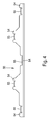
- eine Draufsicht auf ein nicht montiertes Sicherungsblech und
- Figur 5
- eine Teilschnittdarstellung mit einem Anschlussstutzen.
- Die Anschlussvorrichtung gemäß
Figur 1 und2 weist eine aus Blech geformte Montageplatte 10 mit einem quer liegenden Stegteil 11 und an den Seiten jeweils zwei rechtwinklig angeordneten Seitenteilen 12, 13 auf. Das Stegteil 11 weist mauerseitig ein Befestigungsteil 14 mit Öffnungen 15 für Befestigungsschrauben auf. Zur Verstärkung des rechtwinkligen Verlaufs zwischen Stegteil und Befestigungsteil sind entlang der waagrechten Erstreckung beispielsweise vier Sicken 16 in den Winkel der Montageplatte 10 eingearbeitet. - In der Montageplatte sind gemäß
Figur 2 und4 Aufnahmen 18 vorgesehen, in denen Anschlussstutzen für einen Heizkreis und für einen Brauchwasserkreis sowie für einen Gasanschluss 19 des Heizgerätes befestigt. Ein erster Anschlussstutzen 21 ist mit einem Heizungsvorlauf 31 und ein zweiter Anschlussstutzen 22 mit dem Heizungsrücklauf 32 verbunden. An einen dritten Anschlussstutzen 23 ist die Einlassleitung 33 für das Trinkwasser und an einen vierten Anschlussstutzen 24 eine Auslassleitung 34 für das Trinkwasser gekoppelt. Ein weiterer Anschlussstutzen 20 ist als Gasarmatur mit einem Absperrventil 25 ausgeführt, wobei an den Anschlussstutzen 20 die Gasleitung 19 zugeführt ist. Die Auslassleitung 34 führt somit zu den Warmwasserzapfstellen des Brauchwasserkreises. Die Anschlussstutzen 21, 22, 23 sind jeweils als Absperrventile 26, 27, 28 mit jeweils einem Absperrschieber 36, der über eine Schlitzschraube betätigt wird, ausgeführt. Die Absperrventile 26 und 27 für den Heizkreis 31, 32 sind jeweils in ein 3-Wege-Ventil 37 integriert. Die beiden Anschlussstutzen 21, 22 sind ferner über einen Bypass 39 miteinander verbunden, in dem eine Drossel 41 eingebaut ist. Der Anschlussstutzen 23 für die Kaltwasserführung ist ebenfalls mit einem 3-Wege-Ventil 43 verbunden. - Gemäß dem vorliegenden Ausführungsbeispiel sind alle Anschlussstutzen 21, 22, 23, 24 in den Aufnahmen 18 mittels eines gemeinsamen, schienenförmigen Sicherungsblechs 50, wie später noch näher beschrieben wird, arretiert. Das Sicherungsblech 50 ist dabei beispielsweise mittels vier Befestigungsschrauben 51 in jeweils dazu an der Montageplatte 10 ausgebildeten Befestigungslaschen 52 befestigt. Es ist aber auch möglich, nur einzelne Anschlussstutzen mittels eines gemeinsamen Sicherungsblechs 50 zu arretieren.
- Aus
Figur 3 geht eine Draufsicht auf eine einzelne Montageplatte 10 hervor. Die Darstellung verdeutlicht die Ausbildung der Aufnahmen 18 für die einzelnen Anschlussstutzen 21, 22, 23, 24. Jede Aufnahme 18 besitzt einen Einführabschnitt 61, einen Führungsabschnitt 62 und einen Anschlagabschnitt 63. Der Anschlagabschnitt 63 ist in der Tiefe mit einem abgewinkelten Blechteil mit jeweils einem Anschlag 64 ausgeführt. - Bei dem in
Figur 4 dargestellten Sicherungsblech 50 ist für jede Aufnahme 18 der Montageplatte 10 ein Sicherungsabschnitt 54 ausgebildet, dem jeweils eine als gebogene Blechlasche ausgebildeter Anschlag 55 zugeordnet ist. - Die Befestigung eines Anschlussstutzens 21, 22, 23, 24 in der Montageplatte 10 ist am Beispiel des Anschlussstutzens 21 in
Figur 5 dargestellt. Dabei weist der Anschlussstutzen 21 einen geräteseitigen Anschlusskörper 71 und einen leitungsseitigen Anschlusskörper 72 auf. Der leitungsseitige Anschlusskörper 72 ist in denFiguren 1 und2 mit dem Absperrventil 26 und dem 3-Wege-Ventil 37 ausgestattet. Zwischen geräteseitigem Anschlusskörper 71 und leitungsseitigem Anschlusskörper 72 ist eine Hinterschneidung 73 ausgeführt, die im Durchmesser so bemessen ist, dass diese in den Halteabschnitt 62 der jeweiligen Aufnahme 18 der Montageplatte 10 eingreift und dadurch der Anschlusskörper in der Aufnahme 18 längsverschiebbar bis zum Anschlag 64 einsteckbar ist. Nachdem alle Aufnahmen 18 mit den jeweiligen Anschlussstutzen bestückt sind, wird frontseitig das Sicherungsblech 50 aufgeschoben, wobei die Anschläge 55 der Sicherungsabschnitte 54 ebenfalls an dem jeweiligen Anschlagstutzen angreifen und somit die Anschlussstutzen 20, 21, 22, 23, 24 in der Montageplatte 10 fixiert sind. - Bei einer weiteren Ausführungsform dient das Sicherungsblech 50 lediglich zur Arretierung der Anschlussstutzen 21, 22, 23, 24. Der Anschlussstutzen 20 für die Gasarmatur ist dann mit einem separaten Sicherungsblech, einem Sicherungsring oder ähnlichem arretiert.
- Beim Auswechseln eines defekten Absperrventils muss lediglich das Sicherungsblech 50 entfernt werden und der dem defekten Absperrventil zugeordnete Anschlussstutzen kann nach Lösen der zugehörigen leitungsseitigen und geräteseitigen Verschraubungen frontal aus der Montageplatte 10 entnommen werden. Um die Austauschbarkeit einfach zu gestalten, ist zusätzlich zweckmäßig, flach dichtende Verschraubungen für den Heizkreis und den Trinkwasserkreis zu verwenden.
-
- 10
- Montageplatte
- 11
- Stegteil
- 12
- Seitenteil
- 13
- Seitenteil
- 14
- Befestigungsteil
- 15
- Löcher
- 16
- Sicke
- 18
- Aufnahmen
- 19
- Gasanschluss
- 20
- Anschlussstutzen für Gasarmatur
- 21
- Anschlussstutzen
- 22
- Anschlussstutzen
- 23
- Anschlussstutzen
- 24
- Anschlussstutzen
- 25
- Absperrventil für Gasanschluss
- 26
- Absperrventil
- 27
- Absperrventil
- 28
- Absperrventil
- 31
- Heizungsvorlauf
- 32
- Heizungsrücklauf
- 33
- Einlassleitung
- 34
- Auslassleitung
- 36
- Absperrschieber
- 37
- 3-Wege-Ventil
- 39
- Bypassleitung
- 41
- Drossel
- 43
- 3-Wege-Ventil
- 50
- Sicherungsblech
- 51
- Befestigungsschrauben
- 52
- Befestigungslaschen
- 54
- Sicherungsabschnitt
- 55
- Anschlag
- 61
- Einführabschnitt
- 62
- Führungsabschnitt
- 63
- Anschlagabschnitt
- 64
- Anschlag
- 71
- geräteseitiger Anschlusskörper
- 72
- leitungsseitiger Anschlusskörper
- 73
- Hinterschneidung
Claims (1)
- Anschlussvorrichtung für ein Wandheizgerät mit einer an einer Wand befestigbaren Montageplatte (10), die mit bau- und geräteseitigen Anschlussstutzen (20, 21, 22, 23, 24), insbesondere für Wasser und Gas versehen ist, wobei die Anschlussstutzen in der Montageplatte (10) fixiert sind und gegebenenfalls Absperrventile enthalten oder mit diesen verbunden sind, dadurch gekennzeichnet, dass die Montageplatte (10) nach einer Seite hin offene Aufnahmen (18) für die Anschlussstutzen (20, 21, 22, 23, 24) aufweist und dass zumindest ein Teil der Anschlussstutzen (20, 21, 22, 23, 24) mittels eines gemeinsamen Sicherungsblechs (50), das an der Montageplatte (10) befestigbar ist, arretiert ist, wobei die Aufnahme (18) einen Einführabschnitt (61), einen Halteabschnitt (62) und einen Anschlagabschnitt (63) aufweist, wobei der Anschlussstutzen (21, 22, 23, 24) mit einer Hinterschneidung (73) in den Halteabschnitt (62) einführbar ist, wobei die Anschlussstutzen (20, 21, 22, 23, 24) an einem Anschlag (64) des Anschlagabschnitts (63) anliegen und wobei frontal das Sicherungsblech (50) mit jeweils einem der jeweiligen Aufnahme (18) zugeordneten Sicherungsabschnitt (54) mittels eines Anschlags (55) ebenfalls am jeweiligen Anschlagstutzen (20, 21, 22, 23, 24) anliegt.
Applications Claiming Priority (2)
| Application Number | Priority Date | Filing Date | Title |
|---|---|---|---|
| DE102004011280 | 2004-03-09 | ||
| DE102004011280A DE102004011280A1 (de) | 2004-03-09 | 2004-03-09 | Anschlussvorrichtung für ein Wandheizgerät |
Publications (3)
| Publication Number | Publication Date |
|---|---|
| EP1574790A2 EP1574790A2 (de) | 2005-09-14 |
| EP1574790A3 EP1574790A3 (de) | 2006-08-09 |
| EP1574790B1 true EP1574790B1 (de) | 2009-06-17 |
Family
ID=34813616
Family Applications (1)
| Application Number | Title | Priority Date | Filing Date |
|---|---|---|---|
| EP05100193A Expired - Lifetime EP1574790B1 (de) | 2004-03-09 | 2005-01-14 | Anschlussvorrichtung für ein Wandheizgerät |
Country Status (3)
| Country | Link |
|---|---|
| EP (1) | EP1574790B1 (de) |
| DE (2) | DE102004011280A1 (de) |
| ES (1) | ES2327242T3 (de) |
Cited By (1)
| Publication number | Priority date | Publication date | Assignee | Title |
|---|---|---|---|---|
| EP4545872A1 (de) * | 2023-10-23 | 2025-04-30 | Glen Dimplex Deutschland GmbH | Rohrstück und gerätemodul für eine kraftwärmemaschine |
Families Citing this family (4)
| Publication number | Priority date | Publication date | Assignee | Title |
|---|---|---|---|---|
| AT510927B1 (de) * | 2010-12-30 | 2013-04-15 | Herz Armaturen Gmbh | Montageplatte |
| EP3462104B1 (de) * | 2017-09-28 | 2020-04-29 | Daikin Industries, Ltd. | Heisswasserversorgungseinheit und verfahren zur herstellung dergleichen |
| CN115103984B (zh) * | 2020-03-23 | 2024-01-09 | 东芝开利株式会社 | 温水生成装置 |
| DE102022131288A1 (de) * | 2022-11-25 | 2024-05-29 | Envola GmbH | Verbindungssystem für Bauteile zur Temperaturkonditionierung eines Gebäudes |
Family Cites Families (2)
| Publication number | Priority date | Publication date | Assignee | Title |
|---|---|---|---|---|
| DE29708221U1 (de) * | 1997-05-07 | 1998-09-03 | Robert Bosch Gmbh, 70469 Stuttgart | Anschlußvorrichtung für Wandheizgeräte |
| DE10109383C2 (de) * | 2001-02-27 | 2003-04-10 | Viessmann Gmbh & Co | Justierelementensatz für Gashähne |
-
2004
- 2004-03-09 DE DE102004011280A patent/DE102004011280A1/de not_active Ceased
-
2005
- 2005-01-14 EP EP05100193A patent/EP1574790B1/de not_active Expired - Lifetime
- 2005-01-14 ES ES05100193T patent/ES2327242T3/es not_active Expired - Lifetime
- 2005-01-14 DE DE502005007480T patent/DE502005007480D1/de not_active Expired - Lifetime
Cited By (1)
| Publication number | Priority date | Publication date | Assignee | Title |
|---|---|---|---|---|
| EP4545872A1 (de) * | 2023-10-23 | 2025-04-30 | Glen Dimplex Deutschland GmbH | Rohrstück und gerätemodul für eine kraftwärmemaschine |
Also Published As
| Publication number | Publication date |
|---|---|
| ES2327242T3 (es) | 2009-10-27 |
| DE102004011280A1 (de) | 2005-09-29 |
| EP1574790A3 (de) | 2006-08-09 |
| EP1574790A2 (de) | 2005-09-14 |
| DE502005007480D1 (de) | 2009-07-30 |
Similar Documents
| Publication | Publication Date | Title |
|---|---|---|
| EP1006244B1 (de) | Befestigungsanordnung für sanitäre Bauteile | |
| DE102007043309B4 (de) | Sanitärarmatur | |
| EP0580551B1 (de) | Anschlussplatte zum Befestigen von beispielsweise sanitären Armaturen | |
| EP2196584A1 (de) | Verteiler für eine Wasserleitungsanlage | |
| EP2177690A1 (de) | Haltevorrichtung für eine Sicherungsbaugruppe, insbesondere für Fangwände oder -netze | |
| EP0309397B2 (de) | Sanitäre Wasseranschlussanordnung | |
| EP1574790A2 (de) | Anschlussvorrichtung für ein Wandheizgerät | |
| DE4008774C2 (de) | Vorrichtung zur Befestigung von Installationselementen | |
| EP1760205A1 (de) | Anschlussblock für eine Sanitärarmatur und System von Sanitärarmaturen | |
| EP3055463B1 (de) | Vorrichtung zum anschluss von sanitärarmaturen | |
| DE2930518C2 (de) | Einrichtung zum Anschluß einer Leitungsarmatur | |
| EP1692349A1 (de) | Einbauvorrichtung für sanit rarmaturen | |
| DE3419938A1 (de) | Anschlussdose fuer brauchwasser-installationen | |
| DE29614972U1 (de) | Montageschablone für das lagegerechte Montieren der rohrleitungsseitigen Vor- und Rücklaufanschlüsse für Heizkörper | |
| EP0812401A1 (de) | Sanitäres wasserventil | |
| EP4737654A1 (de) | Wanddurchführung | |
| DE102015203854B4 (de) | Anschlussanordnung zur Behandlung von Wasser in einem Wassernetz | |
| DE19805862C1 (de) | Vorrichtung zum Ausrichten einer Heizkörperverkleidung | |
| DE102020209623B4 (de) | Montageplatte zur Wandmontage zumindest zweier Installationsfittings, Montagesystem sowie Verfahren zur Montage | |
| DE20013996U1 (de) | Konvektionsbremse für Wärmequellen | |
| DE10212477B4 (de) | Wasserarmatur mit einer Bodenplatte | |
| EP2146010A1 (de) | Fitting | |
| EP2659197A2 (de) | Montageplatte | |
| EP1571268A1 (de) | Sanitäre Auslaufarmatur | |
| DE102022129803A1 (de) | Waschtisch-Verteilermodul |
Legal Events
| Date | Code | Title | Description |
|---|---|---|---|
| PUAI | Public reference made under article 153(3) epc to a published international application that has entered the european phase |
Free format text: ORIGINAL CODE: 0009012 |
|
| AK | Designated contracting states |
Kind code of ref document: A2 Designated state(s): AT BE BG CH CY CZ DE DK EE ES FI FR GB GR HU IE IS IT LI LT LU MC NL PL PT RO SE SI SK TR |
|
| AX | Request for extension of the european patent |
Extension state: AL BA HR LV MK YU |
|
| PUAL | Search report despatched |
Free format text: ORIGINAL CODE: 0009013 |
|
| AK | Designated contracting states |
Kind code of ref document: A3 Designated state(s): AT BE BG CH CY CZ DE DK EE ES FI FR GB GR HU IE IS IT LI LT LU MC NL PL PT RO SE SI SK TR |
|
| AX | Request for extension of the european patent |
Extension state: AL BA HR LV MK YU |
|
| 17P | Request for examination filed |
Effective date: 20070209 |
|
| AKX | Designation fees paid |
Designated state(s): DE ES FR GB IT |
|
| 17Q | First examination report despatched |
Effective date: 20070913 |
|
| GRAP | Despatch of communication of intention to grant a patent |
Free format text: ORIGINAL CODE: EPIDOSNIGR1 |
|
| GRAS | Grant fee paid |
Free format text: ORIGINAL CODE: EPIDOSNIGR3 |
|
| GRAA | (expected) grant |
Free format text: ORIGINAL CODE: 0009210 |
|
| AK | Designated contracting states |
Kind code of ref document: B1 Designated state(s): DE ES FR GB IT |
|
| REG | Reference to a national code |
Ref country code: GB Ref legal event code: FG4D Free format text: NOT ENGLISH |
|
| REF | Corresponds to: |
Ref document number: 502005007480 Country of ref document: DE Date of ref document: 20090730 Kind code of ref document: P |
|
| REG | Reference to a national code |
Ref country code: ES Ref legal event code: FG2A Ref document number: 2327242 Country of ref document: ES Kind code of ref document: T3 |
|
| PLBE | No opposition filed within time limit |
Free format text: ORIGINAL CODE: 0009261 |
|
| STAA | Information on the status of an ep patent application or granted ep patent |
Free format text: STATUS: NO OPPOSITION FILED WITHIN TIME LIMIT |
|
| 26N | No opposition filed |
Effective date: 20100318 |
|
| REG | Reference to a national code |
Ref country code: FR Ref legal event code: PLFP Year of fee payment: 12 |
|
| REG | Reference to a national code |
Ref country code: FR Ref legal event code: PLFP Year of fee payment: 13 |
|
| REG | Reference to a national code |
Ref country code: FR Ref legal event code: PLFP Year of fee payment: 14 |
|
| PGFP | Annual fee paid to national office [announced via postgrant information from national office to epo] |
Ref country code: GB Payment date: 20180125 Year of fee payment: 14 Ref country code: ES Payment date: 20180201 Year of fee payment: 14 |
|
| PGFP | Annual fee paid to national office [announced via postgrant information from national office to epo] |
Ref country code: FR Payment date: 20180124 Year of fee payment: 14 Ref country code: IT Payment date: 20180126 Year of fee payment: 14 |
|
| REG | Reference to a national code |
Ref country code: DE Ref legal event code: R084 Ref document number: 502005007480 Country of ref document: DE |
|
| PGFP | Annual fee paid to national office [announced via postgrant information from national office to epo] |
Ref country code: DE Payment date: 20190326 Year of fee payment: 15 |
|
| GBPC | Gb: european patent ceased through non-payment of renewal fee |
Effective date: 20190114 |
|
| PG25 | Lapsed in a contracting state [announced via postgrant information from national office to epo] |
Ref country code: FR Free format text: LAPSE BECAUSE OF NON-PAYMENT OF DUE FEES Effective date: 20190131 |
|
| PG25 | Lapsed in a contracting state [announced via postgrant information from national office to epo] |
Ref country code: GB Free format text: LAPSE BECAUSE OF NON-PAYMENT OF DUE FEES Effective date: 20190114 |
|
| PG25 | Lapsed in a contracting state [announced via postgrant information from national office to epo] |
Ref country code: IT Free format text: LAPSE BECAUSE OF NON-PAYMENT OF DUE FEES Effective date: 20190114 |
|
| REG | Reference to a national code |
Ref country code: ES Ref legal event code: FD2A Effective date: 20200309 |
|
| PG25 | Lapsed in a contracting state [announced via postgrant information from national office to epo] |
Ref country code: ES Free format text: LAPSE BECAUSE OF NON-PAYMENT OF DUE FEES Effective date: 20190115 |
|
| REG | Reference to a national code |
Ref country code: DE Ref legal event code: R119 Ref document number: 502005007480 Country of ref document: DE |
|
| PG25 | Lapsed in a contracting state [announced via postgrant information from national office to epo] |
Ref country code: DE Free format text: LAPSE BECAUSE OF NON-PAYMENT OF DUE FEES Effective date: 20200801 |