EP1574462B1 - Dosiervorrichtung - Google Patents
Dosiervorrichtung Download PDFInfo
- Publication number
- EP1574462B1 EP1574462B1 EP05005010A EP05005010A EP1574462B1 EP 1574462 B1 EP1574462 B1 EP 1574462B1 EP 05005010 A EP05005010 A EP 05005010A EP 05005010 A EP05005010 A EP 05005010A EP 1574462 B1 EP1574462 B1 EP 1574462B1
- Authority
- EP
- European Patent Office
- Prior art keywords
- screw
- agitator
- feed metering
- metering
- unit
- Prior art date
- Legal status (The legal status is an assumption and is not a legal conclusion. Google has not performed a legal analysis and makes no representation as to the accuracy of the status listed.)
- Expired - Lifetime
Links
- 239000000843 powder Substances 0.000 claims abstract description 3
- 239000000463 material Substances 0.000 claims description 16
- 238000004140 cleaning Methods 0.000 description 3
- 230000032258 transport Effects 0.000 description 3
- 241000237858 Gastropoda Species 0.000 description 2
- 239000007787 solid Substances 0.000 description 2
- 238000003756 stirring Methods 0.000 description 2
- 230000001419 dependent effect Effects 0.000 description 1
- 238000011161 development Methods 0.000 description 1
- 230000018109 developmental process Effects 0.000 description 1
- 235000013312 flour Nutrition 0.000 description 1
- 230000009969 flowable effect Effects 0.000 description 1
- 238000000034 method Methods 0.000 description 1
- 239000000203 mixture Substances 0.000 description 1
Images
Classifications
-
- B—PERFORMING OPERATIONS; TRANSPORTING
- B65—CONVEYING; PACKING; STORING; HANDLING THIN OR FILAMENTARY MATERIAL
- B65G—TRANSPORT OR STORAGE DEVICES, e.g. CONVEYORS FOR LOADING OR TIPPING, SHOP CONVEYOR SYSTEMS OR PNEUMATIC TUBE CONVEYORS
- B65G65/00—Loading or unloading
- B65G65/30—Methods or devices for filling or emptying bunkers, hoppers, tanks, or like containers, of interest apart from their use in particular chemical or physical processes or their application in particular machines, e.g. not covered by a single other subclass
- B65G65/34—Emptying devices
- B65G65/40—Devices for emptying otherwise than from the top
- B65G65/46—Devices for emptying otherwise than from the top using screw conveyors
- B65G65/463—Devices for emptying otherwise than from the top using screw conveyors arranged vertically or substantially vertically within the container
Definitions
- the invention relates to a metering device according to the preamble of claim 1.
- dosing devices For continuous or pulsed dosing of small quantities of bulk solids, especially fine powders, dosing devices with dosing screws are used. They serve as feeders to process equipment or as a device for filling containers.
- These devices consist essentially of a storage container, one or more metering screws and optionally a stirring member which supplies the material to be metered the screw conveyor.
- the screw feeder in which the metering screw is arranged horizontally below the reservoir here is the DE 43 36 685 C2 to give as an example.
- the screw feeder in which the screw is arranged vertically in a rotationally symmetrical dosing and concentrically surrounded by a stirrer as shown in the US 3,269,527 is described.
- the JP 60 137713 A describes a metering device with a metering screw on the Dosier irritationer anger and a busy with blades rotating stirrer. This conveys the material in the metering device to the discharge tube and prevents material bridging.
- the DE 645095 discloses a mixing vessel with elevator.
- a screw conveyor projects with its lower end into the container, the material, here flour falls by its own weight into the height conveyor and is transported upwards.
- the mixing container is also equipped with a mixing device, eg an upwardly conveying screw.
- the object of the invention is to provide a metering device which allows a constant supply of material to the metering screw even with difficult flowing bulk materials and which provides a simple disassembly of stirrer and metering screw for cleaning purposes, in particular with regard to the expansion of the product side shaft seals.
- a significant advantage of the invention is that the worm shaft is not arranged concentrically with the stirrer in the dosing, but eccentric as close to the wall of the dosing.
- the stirrer is arranged concentrically to the metering container, wherein the stirring arm is guided as close as possible to the container wall. He performs an oscillating movement. This prevents poorly flowable products from being rotated around the screw by the agitator without realizing supply of material to the screw.
- the material is inevitably guided by the stirrer to the screw, detected by this and transported down through the metering tube.
- the design of the device with separate shafts and bearings for stirrer and screw allows easy release of the dosing with stirrer and screw from the storage and drive unit. Thereafter, the lid of the dosing, the stirrer, the screw and the shaft seals can be removed for cleaning purposes.
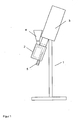
- the metering device 1 consists of the metering 2 with stirrer and screw and a drive unit 3.
- the metering 2 is provided with a hopper 4 for the material supply.
- an automatic feed for example, with a horizontal auger can be used.
- the supplied material is guided in the dosing 2 by the stirrer to the screw and metered via the dosing 5 a machine, a system or a container.
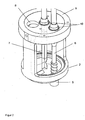
- FIG. 2 the metering container 2 with the arrangement of the metering screw 6 and the stirrer 7 is shown.
- the dosing tank 2 is designed rotationally symmetrical.
- the screw 6 is arranged eccentrically parallel to the stirrer axis in the metering container 2 as close as possible to the wall of the container.
- the screw threads extend from the dosing tank into the dosing tube.
- the stirrer 7 is arranged axially centrally in the rotationally symmetrical metering container 6. By the shaft seals 10, the waves of agitator 6 and screw 6 are sealed against the lid and the environment.
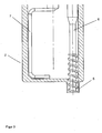
- the stirrer 7 has a hook-shaped form, so that it is possible wall and near the bottom in the dosing, which is designed rotationally symmetrical at least in the region of the screw outlet.
- the stirrer 7 can be designed with one arm or with more than one arm.
- the stirrer 7 performs an oscillating movement. He moves with one arm until just before the screw 6 and transports material before him to transport it into the screw. Then he turns in the opposite direction to also move to just before the snail and transport the material into the snail.
Landscapes
- Engineering & Computer Science (AREA)
- Mechanical Engineering (AREA)
- Accessories For Mixers (AREA)
- Closures For Containers (AREA)
- Feeding, Discharge, Calcimining, Fusing, And Gas-Generation Devices (AREA)
- Filling Or Emptying Of Bunkers, Hoppers, And Tanks (AREA)
- Eye Examination Apparatus (AREA)
- Measuring Pulse, Heart Rate, Blood Pressure Or Blood Flow (AREA)
- Drying Of Semiconductors (AREA)
- Basic Packing Technique (AREA)
Description
- Die Erfindung betrifft eine Dosiervorrichtung nach dem Oberbegriff des Anspruchs 1.
- Für die kontinuierliche oder getaktete Dosierung von kleinen Mengen Schüttgütern, speziell feinen Pulvern, kommen Dosiervorrichtungen mit Dosierschnecken zum Einsatz. Sie dienen als Zuführeinrichtungen an prozeßtechnischen Anlage oder als Einrichtung zum Befüllen von Gebinden.
- Diese Vorrichtungen bestehen im wesentlichen aus einem Vorratssbehälter, einer oder mehreren Dosierschnecken und wahlweise einem Rührorgan, welches das zu dosierende Material der Förderschnecke zuführt.
- Hierbei haben sich zwei Varianten ausgebildet. Zum einen die Schneckendosierer bei denen die Dosierschnecke unterhalb des Vorratsbehälters waagerecht angeordnet ist, hier ist die
DE 43 36 685 C2 als Beispiel zu nennen. Zum anderen Dosiervorrichtungen bei denen die Schnecke senkrecht in einem rotationssymmetrischen Dosierbehälter angeordnet ist und konzentrisch von einem Rührer umgeben wird, wie sie in derUS 3,269,527 beschrieben ist. - Die
JP 60 137713 A - Die
DE 645095 offenbart einen Mischbehälter mit Höhenförderer. Eine Förderschnecke ragt mit ihrem unteren Ende in den Behälter, das Material, hier Mehl fällt durch sein Eigengewicht in den Höhenförderer und wird nach oben transportiert. Der Mischbehälter ist außerdem mit einer Mischvorrichtung, z.B. einer nach oben fördernden Schnecke ausgestattet. - Bei schwer fließfähigen Schüttgütern kommt es bei rotationssymmetrisch ausgestalteten Dosierbehältern mit vertikaler Schnecke und konzentrischem Rührer häufig dazu, daß der Rührer das Material nicht durchmischt und der Schnecke zuführt, sondern das Material im Kreis um die Schnecke bewegt, so daß die Materialzufuhr zur Dosierschnecke und damit die Dosierung unterbrochen ist.
- Die konzentrische Anordnung von Schnecke und Rührer erfordert eine aufwendige Lagerung, da sich die eine Welle in der anderen dreht. Besonders aufwendig wird es dann, wenn die Forderung nach möglichst einfacher Demontage von Rührer und Schnecke zu Reinigungszwecken besteht. Bei Pharma-Anwendungen ist ein Ausbau der produktseitigen Wellendichtringen erwünscht, welches bei einer Ausführungsform mit zwei konzentrischen Wellen nur schwer zu realisieren ist.
- Aufgabe der Erfindung ist es, eine Dosiervorrichtung zu schaffen, die eine konstante Zufuhr von Material an die Dosierschnecke auch bei schwer fließenden Schüttgütern ermöglicht und die eine einfache Demontage von Rührer und Dosierschnecke zu Reinigungszwecken bietet, insbesondere im Hinblick auf den Ausbau der produktseitigen Wellendichtringe.
- Diese Aufgabe wird durch eine Dosiervorrichtung mit den Merkmalen des Anspruchs 1 gelöst. Zweckmäßige Ausgestaltungen und vorteilhafte Weiterbildungen der Erfindung sind in den Unteransprüchen angegeben.
- Ein wesentlicher Vorteil der Erfindung besteht darin, das die Schneckenwelle nicht konzentrisch mit dem Rührer im Dosierbehälter angeordnet ist, sondern, exzentrisch möglichst nah an der Wandung des Dosierbehälters. Der Rührer ist konzentrisch zum Dosierbehälter angeordnet, wobei der Rührarm möglichst nah an der Behälterwand geführt wird. Er führt eine oszillierende Bewegung aus. Dadurch wird verhindert, daß schlecht fließfähige Produkte durch den Rührer um die Schnecke im Kreis gedreht werden ohne eine Zufuhr von Material an die Schnecke zu realisieren. Bei der erfindungsgemäßen Ausgestaltung wird das Material vom Rührer zwangsläufig an die Schnecke geführt, von dieser erfaßt und nach unten durch das Dosierrohr transportiert.
- Die Ausgestaltung der Vorrichtung mit getrennten Wellen und Lagerungen für Rührer und Schnecke ermöglicht ein einfaches Lösen des Dosierbehälters mit Rührer und Schnecke aus der Lager- und Antriebseinheit. Danach kann der Deckel des Dosierbehälters, der Rührer, die Schnecke und die Wellendichtringe zu Reinigungszwecken ausgebaut werden.
- Es besteht die Möglichkeit die Dosiervorrichtung unter einem Neigungswinkel kleiner 90°, vorzugsweise 0 bis 30°, gegenüber der Senkrechten zu betreiben, um auch die Restmengen aus dem Behälter zu dosieren.
- Weitere Besonderheiten und Vorzüge der Erfindung ergeben sich aus der folgenden Beschreibung eines Ausführungsbeispiels anhand der Zeichnungen. Es zeigt:
-
Figur 1 : die Dosiervorrichtung -
Figur 2 : den Dosierbehälter -
Figur 3 : den Dosierbehälter in einer Schnittansicht - In der
Figur 1 ist die Dosiervorrichtung schematisch dargestellt. Die Dosiervorrichtung 1 besteht aus dem Dosierbehälter 2 mit Rührer und Schnecke sowie einer Antriebseinheit 3. Der Dosierbehälter 2 ist mit einem Trichter 4 für die Materialzuführung versehen. Anstatt des Tichters 4 kann auch eine automatische Beschickung z.B. mit horizontaler Förderschnecke eingesetzt werden. Das zugeführte Material wird im Dosierbehälter 2 durch den Rührer zur Schnecke geführt und über das Dosierrohr 5 einer Maschine, einer Anlage oder einem Gebinde zudosiert. - In der
Figur 2 ist der Dosierbehälter 2 mit der Anordnung der Dosierschnecke 6 und des Rührer 7 dargestellt. Der Dosierbehälter 2 ist rotationssymmetrisch ausgeführt. Die Schnecke 6 ist exzentrisch parallel zur Rührerachse im Dosierbehälter 2 möglichst nah an der Wandung des Behälters angeordnet. Die Schneckengänge reichen vom Dosierbehälter bis in das Dosierrohr. Der Rührer 7 ist axial mittig im rotationssymmetrischen Dosierbehälter 6 angeordnet. Durch die Wellendichtringe 10 werden die Wellen von Rührer 6 und Schnecke 6 gegenüber dem Deckel und der Umgebung abgedichtet. - In der Schnittansicht in
Figur 3 ist eine Ausführungsform des Rührers 7 dargestellt. Der Rührer 7 hat eine hakenförmige Gestalt, so daß er möglichst wand- und bodennah im Dosierbehälter, welcher zumindest im Bereich des Schneckenauslaufs rotationssymmetrisch gestaltet ist, geführt wird. Der Rührer 7 kann einarmig oder auch mehrarmig ausgeführt sein. Der Rührer 7 führt eine oszillierende Bewegung aus. Dabei bewegt er sich mit einem Arm bis kurz vor die Schnecke 6 und transportiert dabei Material vor sich her um es in die Schnecke zu befördern. Danach dreht er sich dann in die entgegengesetzte Richtung, um sich ebenfalls bis kurz vor die Schnecke zu bewegen und das Material in die Schnecke zu transportieren.
Claims (5)
- Dosiervorrichtung (1) mit einem Dosierbehälter (2) zum Aufnehmen von Schüttgütern, speziell von feinen Pulvern, einer Dosierschnecke (6) und einem Rührer (7) sowie einer Antriebseinheit (3) für Rührer (7) und Dosierschnecke (6) wobei die Dosierschnecke parallel zur Rührachse, exzentrisch im Dosierbehälter (2) angeordnet ist dadurch gekennzeichnet, dass der Rührer mit mindestens einem wandnahen und bodennahen Rührarm im Dosierbehälter mit rotationssymmetrischen Auslauf, konzentrisch angeordnet ist und oszillierende Bewegungen ausführt.
- Dosiervorrichtung nach Anspruch 1, dadurch gekennzeichnet, daß der Rührer (7) einarmig oder mehrarmig ausgeführt ist.
- Dosiervorrichtung nach einem der Ansprüche 1 bis 2 dadurch gekennzeichnet, daß die Rührerwelle und Dosierschneckenwelle getrennt gelagert sind.
- Dosiervorrichtung nach einem der vorherigen Ansprüche dadurch gekennzeichnet, daß der Winkel der von dem senkrecht angeordneten Bein der Vorrichtung und der Rührerachse eingeschlossen ist zwischen 0 bis 90° beträgt.
- Dosiervorrichtung nach einem der vorherigen Ansprüche dadurch gekennzeichnet, daß der Winkel der von dem senkrecht angeordneten Bein der Vorrichtung und der Rührerachse eingeschlossen ist zwischen 0 bis 30° beträgt.
Applications Claiming Priority (2)
| Application Number | Priority Date | Filing Date | Title |
|---|---|---|---|
| DE102004012613 | 2004-03-12 | ||
| DE102004012613A DE102004012613A1 (de) | 2004-03-12 | 2004-03-12 | Dosiervorrichtung |
Publications (2)
| Publication Number | Publication Date |
|---|---|
| EP1574462A1 EP1574462A1 (de) | 2005-09-14 |
| EP1574462B1 true EP1574462B1 (de) | 2008-03-12 |
Family
ID=34813706
Family Applications (1)
| Application Number | Title | Priority Date | Filing Date |
|---|---|---|---|
| EP05005010A Expired - Lifetime EP1574462B1 (de) | 2004-03-12 | 2005-03-08 | Dosiervorrichtung |
Country Status (3)
| Country | Link |
|---|---|
| EP (1) | EP1574462B1 (de) |
| AT (1) | ATE388914T1 (de) |
| DE (2) | DE102004012613A1 (de) |
Families Citing this family (2)
| Publication number | Priority date | Publication date | Assignee | Title |
|---|---|---|---|---|
| CN105565004B (zh) * | 2016-03-24 | 2017-11-17 | 陈勇 | 改变出料口料流形状的螺旋式给料装置 |
| US20230110920A1 (en) * | 2020-04-02 | 2023-04-13 | Life Technologies Corporation | Powder Hydration Systems with Mixing Apparatus and Methods Of Use |
Family Cites Families (2)
| Publication number | Priority date | Publication date | Assignee | Title |
|---|---|---|---|---|
| DE645095C (de) * | 1935-03-12 | 1937-05-21 | Karl Schmidtmann Dipl Ing | Hoehenfoerderer |
| JPS60137713A (ja) * | 1983-12-24 | 1985-07-22 | Ichieda Sangyo Kk | 定量移送装置 |
-
2004
- 2004-03-12 DE DE102004012613A patent/DE102004012613A1/de not_active Withdrawn
-
2005
- 2005-03-08 EP EP05005010A patent/EP1574462B1/de not_active Expired - Lifetime
- 2005-03-08 DE DE502005003157T patent/DE502005003157D1/de not_active Expired - Lifetime
- 2005-03-08 AT AT05005010T patent/ATE388914T1/de not_active IP Right Cessation
Also Published As
| Publication number | Publication date |
|---|---|
| DE502005003157D1 (de) | 2008-04-24 |
| DE102004012613A1 (de) | 2005-09-29 |
| EP1574462A1 (de) | 2005-09-14 |
| ATE388914T1 (de) | 2008-03-15 |
Similar Documents
| Publication | Publication Date | Title |
|---|---|---|
| EP1036750B1 (de) | Einrichtung zum Fördern von Kunststoffgranulat | |
| DE69814786T2 (de) | Mischer | |
| EP2072974A1 (de) | Laborgerät mit einer dosiergut-führungsvorrichtung | |
| DE102009002630A1 (de) | Vorrichtung zur Fluidisierung und Dosierung pulverförmiger Substanzen | |
| EP1951416B1 (de) | Vorrichtung zur herstellung einer mischung aus verschiedenen schüttgutkomponenten | |
| EP1361185B1 (de) | Vorrichtung zum Zuteilen von fliessfähigen Materialien | |
| DE1531934A1 (de) | Dosierbunker mit eingebauter Dosiervorrichtung fuer schlecht fliessende pulverfoermige Stoffe | |
| DE1298401B (de) | Zwangsmischer mit lotrecht angeordnetem Mischbehaelter | |
| DE2937469C2 (de) | ||
| EP1821083B1 (de) | Dosiervorrichtung zum Dosieren eines Pulvers | |
| WO2001025119A9 (de) | Dosiervorrichtung für schüttgüter | |
| EP1574462B1 (de) | Dosiervorrichtung | |
| EP0150353B1 (de) | Vorrichtung zur Aufbewahrung, Dosierung und Mischung von Mörtel-Materialkomponenten | |
| DE4217373C2 (de) | Vorrichtung zur Aufbereitung und Bereitstellung von wenigstens einen flüssigen Bestandteil enthaltenden Mischungen oder Suspensionen | |
| EP3792207B1 (de) | Dosiervorrichtung | |
| EP3523201B1 (de) | Fülleinrichtung für eine packmaschine zum füllen von schüttgütern in gebinde | |
| DE3534090A1 (de) | Vorrichtung zum dosieren von bestaeubungspuder | |
| DE10245862A1 (de) | Anlage zum Lösen bzw. Mischen von pulverförmigen Substanzen | |
| WO2023100037A1 (de) | Gravimetrische dosiereinheit für fliessfähiges schüttgut | |
| EP3877304B1 (de) | Vorrichtung zum dosieren von schüttgütern | |
| DE102009056335A1 (de) | Vorrichtung zur Förderung und Lagerung von Schüttgütern in Massengutfrachtern | |
| DE3502765C2 (de) | Förderschnecke zum Dosieren | |
| CH659052A5 (en) | Device for the portioned and metered dispensing of bulk materials from a storage container | |
| DE19712177C2 (de) | Vorrichtung zur dosierten Entnahme von körnigen Substanzen | |
| WO2006010475A1 (de) | Dosier- und/oder abfüllvorrichtung für fliessfähiges schüttgut |
Legal Events
| Date | Code | Title | Description |
|---|---|---|---|
| PUAI | Public reference made under article 153(3) epc to a published international application that has entered the european phase |
Free format text: ORIGINAL CODE: 0009012 |
|
| AK | Designated contracting states |
Kind code of ref document: A1 Designated state(s): AT BE BG CH CY CZ DE DK EE ES FI FR GB GR HU IE IS IT LI LT LU MC NL PL PT RO SE SI SK TR |
|
| AX | Request for extension of the european patent |
Extension state: AL BA HR LV MK YU |
|
| 17P | Request for examination filed |
Effective date: 20051201 |
|
| AKX | Designation fees paid |
Designated state(s): AT BE BG CH CY CZ DE DK EE ES FI FR GB GR HU IE IS IT LI LT LU MC NL PL PT RO SE SI SK TR |
|
| 17Q | First examination report despatched |
Effective date: 20060929 |
|
| GRAP | Despatch of communication of intention to grant a patent |
Free format text: ORIGINAL CODE: EPIDOSNIGR1 |
|
| GRAS | Grant fee paid |
Free format text: ORIGINAL CODE: EPIDOSNIGR3 |
|
| GRAA | (expected) grant |
Free format text: ORIGINAL CODE: 0009210 |
|
| AK | Designated contracting states |
Kind code of ref document: B1 Designated state(s): AT BE BG CH CY CZ DE DK EE ES FI FR GB GR HU IE IS IT LI LT LU MC NL PL PT RO SE SI SK TR |
|
| REG | Reference to a national code |
Ref country code: GB Ref legal event code: FG4D Free format text: NOT ENGLISH |
|
| RIN1 | Information on inventor provided before grant (corrected) |
Inventor name: BRENNER, BERTRAM Inventor name: HERRMANN, FRIEDRICH |
|
| REG | Reference to a national code |
Ref country code: CH Ref legal event code: EP |
|
| REG | Reference to a national code |
Ref country code: IE Ref legal event code: FG4D Free format text: LANGUAGE OF EP DOCUMENT: GERMAN |
|
| REF | Corresponds to: |
Ref document number: 502005003157 Country of ref document: DE Date of ref document: 20080424 Kind code of ref document: P |
|
| REG | Reference to a national code |
Ref country code: CH Ref legal event code: NV Representative=s name: SCHMAUDER & PARTNER AG PATENTANWALTSBUERO |
|
| GBT | Gb: translation of ep patent filed (gb section 77(6)(a)/1977) |
Effective date: 20080410 |
|
| PG25 | Lapsed in a contracting state [announced via postgrant information from national office to epo] |
Ref country code: LT Free format text: LAPSE BECAUSE OF FAILURE TO SUBMIT A TRANSLATION OF THE DESCRIPTION OR TO PAY THE FEE WITHIN THE PRESCRIBED TIME-LIMIT Effective date: 20080312 Ref country code: FI Free format text: LAPSE BECAUSE OF FAILURE TO SUBMIT A TRANSLATION OF THE DESCRIPTION OR TO PAY THE FEE WITHIN THE PRESCRIBED TIME-LIMIT Effective date: 20080312 |
|
| NLV1 | Nl: lapsed or annulled due to failure to fulfill the requirements of art. 29p and 29m of the patents act | ||
| PG25 | Lapsed in a contracting state [announced via postgrant information from national office to epo] |
Ref country code: SI Free format text: LAPSE BECAUSE OF FAILURE TO SUBMIT A TRANSLATION OF THE DESCRIPTION OR TO PAY THE FEE WITHIN THE PRESCRIBED TIME-LIMIT Effective date: 20080312 Ref country code: PL Free format text: LAPSE BECAUSE OF FAILURE TO SUBMIT A TRANSLATION OF THE DESCRIPTION OR TO PAY THE FEE WITHIN THE PRESCRIBED TIME-LIMIT Effective date: 20080312 |
|
| PG25 | Lapsed in a contracting state [announced via postgrant information from national office to epo] |
Ref country code: PT Free format text: LAPSE BECAUSE OF FAILURE TO SUBMIT A TRANSLATION OF THE DESCRIPTION OR TO PAY THE FEE WITHIN THE PRESCRIBED TIME-LIMIT Effective date: 20080818 Ref country code: SK Free format text: LAPSE BECAUSE OF FAILURE TO SUBMIT A TRANSLATION OF THE DESCRIPTION OR TO PAY THE FEE WITHIN THE PRESCRIBED TIME-LIMIT Effective date: 20080312 Ref country code: ES Free format text: LAPSE BECAUSE OF FAILURE TO SUBMIT A TRANSLATION OF THE DESCRIPTION OR TO PAY THE FEE WITHIN THE PRESCRIBED TIME-LIMIT Effective date: 20080623 Ref country code: CZ Free format text: LAPSE BECAUSE OF FAILURE TO SUBMIT A TRANSLATION OF THE DESCRIPTION OR TO PAY THE FEE WITHIN THE PRESCRIBED TIME-LIMIT Effective date: 20080312 Ref country code: SE Free format text: LAPSE BECAUSE OF FAILURE TO SUBMIT A TRANSLATION OF THE DESCRIPTION OR TO PAY THE FEE WITHIN THE PRESCRIBED TIME-LIMIT Effective date: 20080612 |
|
| PG25 | Lapsed in a contracting state [announced via postgrant information from national office to epo] |
Ref country code: NL Free format text: LAPSE BECAUSE OF FAILURE TO SUBMIT A TRANSLATION OF THE DESCRIPTION OR TO PAY THE FEE WITHIN THE PRESCRIBED TIME-LIMIT Effective date: 20080312 Ref country code: RO Free format text: LAPSE BECAUSE OF FAILURE TO SUBMIT A TRANSLATION OF THE DESCRIPTION OR TO PAY THE FEE WITHIN THE PRESCRIBED TIME-LIMIT Effective date: 20080312 |
|
| PG25 | Lapsed in a contracting state [announced via postgrant information from national office to epo] |
Ref country code: IS Free format text: LAPSE BECAUSE OF FAILURE TO SUBMIT A TRANSLATION OF THE DESCRIPTION OR TO PAY THE FEE WITHIN THE PRESCRIBED TIME-LIMIT Effective date: 20080712 |
|
| EN | Fr: translation not filed | ||
| PLBE | No opposition filed within time limit |
Free format text: ORIGINAL CODE: 0009261 |
|
| STAA | Information on the status of an ep patent application or granted ep patent |
Free format text: STATUS: NO OPPOSITION FILED WITHIN TIME LIMIT |
|
| PG25 | Lapsed in a contracting state [announced via postgrant information from national office to epo] |
Ref country code: DK Free format text: LAPSE BECAUSE OF FAILURE TO SUBMIT A TRANSLATION OF THE DESCRIPTION OR TO PAY THE FEE WITHIN THE PRESCRIBED TIME-LIMIT Effective date: 20080312 |
|
| 26N | No opposition filed |
Effective date: 20081215 |
|
| PG25 | Lapsed in a contracting state [announced via postgrant information from national office to epo] |
Ref country code: BG Free format text: LAPSE BECAUSE OF FAILURE TO SUBMIT A TRANSLATION OF THE DESCRIPTION OR TO PAY THE FEE WITHIN THE PRESCRIBED TIME-LIMIT Effective date: 20080612 Ref country code: EE Free format text: LAPSE BECAUSE OF FAILURE TO SUBMIT A TRANSLATION OF THE DESCRIPTION OR TO PAY THE FEE WITHIN THE PRESCRIBED TIME-LIMIT Effective date: 20080312 Ref country code: FR Free format text: LAPSE BECAUSE OF FAILURE TO SUBMIT A TRANSLATION OF THE DESCRIPTION OR TO PAY THE FEE WITHIN THE PRESCRIBED TIME-LIMIT Effective date: 20090102 |
|
| PGFP | Annual fee paid to national office [announced via postgrant information from national office to epo] |
Ref country code: IE Payment date: 20090219 Year of fee payment: 5 |
|
| REG | Reference to a national code |
Ref country code: CH Ref legal event code: PCAR Free format text: SCHMAUDER & PARTNER AG PATENT- UND MARKENANWAELTE VSP;ZWAENGIWEG 7;8038 ZUERICH (CH) |
|
| BERE | Be: lapsed |
Owner name: HOSOKAWA ALPINE A.G. Effective date: 20090331 |
|
| PG25 | Lapsed in a contracting state [announced via postgrant information from national office to epo] |
Ref country code: CY Free format text: LAPSE BECAUSE OF FAILURE TO SUBMIT A TRANSLATION OF THE DESCRIPTION OR TO PAY THE FEE WITHIN THE PRESCRIBED TIME-LIMIT Effective date: 20080312 |
|
| PG25 | Lapsed in a contracting state [announced via postgrant information from national office to epo] |
Ref country code: MC Free format text: LAPSE BECAUSE OF NON-PAYMENT OF DUE FEES Effective date: 20090331 |
|
| PG25 | Lapsed in a contracting state [announced via postgrant information from national office to epo] |
Ref country code: BE Free format text: LAPSE BECAUSE OF NON-PAYMENT OF DUE FEES Effective date: 20090331 |
|
| PG25 | Lapsed in a contracting state [announced via postgrant information from national office to epo] |
Ref country code: AT Free format text: LAPSE BECAUSE OF NON-PAYMENT OF DUE FEES Effective date: 20090308 |
|
| PG25 | Lapsed in a contracting state [announced via postgrant information from national office to epo] |
Ref country code: GR Free format text: LAPSE BECAUSE OF FAILURE TO SUBMIT A TRANSLATION OF THE DESCRIPTION OR TO PAY THE FEE WITHIN THE PRESCRIBED TIME-LIMIT Effective date: 20080613 |
|
| PG25 | Lapsed in a contracting state [announced via postgrant information from national office to epo] |
Ref country code: IE Free format text: LAPSE BECAUSE OF NON-PAYMENT OF DUE FEES Effective date: 20100308 |
|
| PG25 | Lapsed in a contracting state [announced via postgrant information from national office to epo] |
Ref country code: LU Free format text: LAPSE BECAUSE OF NON-PAYMENT OF DUE FEES Effective date: 20090308 |
|
| PG25 | Lapsed in a contracting state [announced via postgrant information from national office to epo] |
Ref country code: HU Free format text: LAPSE BECAUSE OF FAILURE TO SUBMIT A TRANSLATION OF THE DESCRIPTION OR TO PAY THE FEE WITHIN THE PRESCRIBED TIME-LIMIT Effective date: 20080913 |
|
| PG25 | Lapsed in a contracting state [announced via postgrant information from national office to epo] |
Ref country code: TR Free format text: LAPSE BECAUSE OF FAILURE TO SUBMIT A TRANSLATION OF THE DESCRIPTION OR TO PAY THE FEE WITHIN THE PRESCRIBED TIME-LIMIT Effective date: 20080312 |
|
| PGFP | Annual fee paid to national office [announced via postgrant information from national office to epo] |
Ref country code: IT Payment date: 20120323 Year of fee payment: 8 Ref country code: GB Payment date: 20120307 Year of fee payment: 8 |
|
| GBPC | Gb: european patent ceased through non-payment of renewal fee |
Effective date: 20130308 |
|
| PG25 | Lapsed in a contracting state [announced via postgrant information from national office to epo] |
Ref country code: GB Free format text: LAPSE BECAUSE OF NON-PAYMENT OF DUE FEES Effective date: 20130308 |
|
| PG25 | Lapsed in a contracting state [announced via postgrant information from national office to epo] |
Ref country code: IT Free format text: LAPSE BECAUSE OF NON-PAYMENT OF DUE FEES Effective date: 20130308 |
|
| REG | Reference to a national code |
Ref country code: CH Ref legal event code: PUE Owner name: FRIEDRICH HERRMANN, DE Free format text: FORMER OWNER: HOSOKAWA ALPINE AKTIENGESELLSCHAFT, DE |
|
| REG | Reference to a national code |
Ref country code: DE Ref legal event code: R081 Ref document number: 502005003157 Country of ref document: DE Owner name: HERRMANN, FRIEDRICH, DE Free format text: FORMER OWNER: HOSOKAWA ALPINE AG, 86199 AUGSBURG, DE |
|
| PGFP | Annual fee paid to national office [announced via postgrant information from national office to epo] |
Ref country code: DE Payment date: 20230822 Year of fee payment: 19 |
|
| PGFP | Annual fee paid to national office [announced via postgrant information from national office to epo] |
Ref country code: CH Payment date: 20240401 Year of fee payment: 20 |
|
| REG | Reference to a national code |
Ref country code: DE Ref legal event code: R119 Ref document number: 502005003157 Country of ref document: DE |
|
| PG25 | Lapsed in a contracting state [announced via postgrant information from national office to epo] |
Ref country code: DE Free format text: LAPSE BECAUSE OF NON-PAYMENT OF DUE FEES Effective date: 20241001 |
|
| PG25 | Lapsed in a contracting state [announced via postgrant information from national office to epo] |
Ref country code: DE Free format text: LAPSE BECAUSE OF NON-PAYMENT OF DUE FEES Effective date: 20241001 |
|
| REG | Reference to a national code |
Ref country code: CH Ref legal event code: PL |