EP1574302B1 - Manipulator with an umbilical-member managing system - Google Patents
Manipulator with an umbilical-member managing system Download PDFInfo
- Publication number
- EP1574302B1 EP1574302B1 EP05004967A EP05004967A EP1574302B1 EP 1574302 B1 EP1574302 B1 EP 1574302B1 EP 05004967 A EP05004967 A EP 05004967A EP 05004967 A EP05004967 A EP 05004967A EP 1574302 B1 EP1574302 B1 EP 1574302B1
- Authority
- EP
- European Patent Office
- Prior art keywords
- umbilical
- axis
- working tool
- manipulator
- forearm
- Prior art date
- Legal status (The legal status is an assumption and is not a legal conclusion. Google has not performed a legal analysis and makes no representation as to the accuracy of the status listed.)
- Expired - Fee Related
Links
- 238000003466 welding Methods 0.000 claims description 110
- 210000000707 wrist Anatomy 0.000 claims description 59
- 210000000245 forearm Anatomy 0.000 claims description 49
- 230000007246 mechanism Effects 0.000 claims description 29
- 230000008859 change Effects 0.000 description 14
- 230000006835 compression Effects 0.000 description 5
- 238000007906 compression Methods 0.000 description 5
- 230000005484 gravity Effects 0.000 description 5
- 230000004048 modification Effects 0.000 description 3
- 238000012986 modification Methods 0.000 description 3
- 230000004044 response Effects 0.000 description 3
- 239000000126 substance Substances 0.000 description 3
- 239000000758 substrate Substances 0.000 description 3
- 239000012636 effector Substances 0.000 description 2
- 230000000694 effects Effects 0.000 description 2
- 238000000034 method Methods 0.000 description 2
- 230000002093 peripheral effect Effects 0.000 description 2
- 238000004088 simulation Methods 0.000 description 2
- 239000006096 absorbing agent Substances 0.000 description 1
- 230000009471 action Effects 0.000 description 1
- 230000003247 decreasing effect Effects 0.000 description 1
- 238000005516 engineering process Methods 0.000 description 1
- 238000011835 investigation Methods 0.000 description 1
- 239000007788 liquid Substances 0.000 description 1
- 239000000463 material Substances 0.000 description 1
- 230000008569 process Effects 0.000 description 1
- 230000035939 shock Effects 0.000 description 1
Images


Classifications
-
- B—PERFORMING OPERATIONS; TRANSPORTING
- B25—HAND TOOLS; PORTABLE POWER-DRIVEN TOOLS; MANIPULATORS
- B25J—MANIPULATORS; CHAMBERS PROVIDED WITH MANIPULATION DEVICES
- B25J19/00—Accessories fitted to manipulators, e.g. for monitoring, for viewing; Safety devices combined with or specially adapted for use in connection with manipulators
- B25J19/0025—Means for supplying energy to the end effector
Definitions
- the present invention relates to a manipulator having an umbilical-member managing system.
- an industrial robot is used in a condition where a working tool (i.e., an end effector) is attached to the distal end of a wrist.
- Electrical energy, an electric signal and/or a substance such as a gas or a liquid are supplied to the working tool through a cable, a pipe, etc.
- a welding wire is supplied to the welding torch through a torch cable.
- a member such as a cable, a pipe, etc., used for supplying energy, a signal, a substance (including a welding wire), or the like, to a working tool, is generally referred to as an "umbilical member".
- robot an industrial robot
- various objects such as a workpiece, a jig, peripheral equipment, etc.
- the arm, the wrist and the working tool, provided at the distal end of the robot can operate in a relatively narrow space, which substantially eliminates a problem of interference between them and surrounding objects.
- umbilical member for the working tool without giving rise to interference with the surrounding objects.
- the umbilical member is usually laid in a gently curved form, and as a result, the operational space of the robot is enlarged, which leads to a problem of interference with the surrounding objects.
- the umbilical member is liable to interfere with objects such as a workpiece, a jig or peripheral equipment.
- JP 5-28563 U discloses an arc welding robot requiring a welding wire to be supplied to a welding torch, in which a wire feeding device is mounted on a support base provided in a robot arm.
- Figs. 1A and 1B schematically show the configuration of this arc welding robot, in which Fig. 1A is a front view showing the entire configuration of the welding robot, and Fig. 1B is a side view showing the distal end region of the arm of the welding robot as seen from the left side of Fig. 1 .
- a welding torch 2 is attached to the distal end of a wrist of a robot mechanical section 1, and a wire feeding device 4 is mounted on a support base 5 of a robot arm (forearm) for feeding a welding wire to the welding torch 2 through a torch cable 3.
- the wire feeding device 4 is constructed so as to be adjustable in reciprocating motion (or slidable) along the feeding direction of the welding wire, through a shift unit (or a slide mechanism) 6 adapted to be controlled for the position thereof by a control section (not shown) for the robot arm.
- a wrist axis provided in the robot performs an orientation change (i.e., a turning) of the welding torch 2
- the behavior of the torch cable 3 exhibits a large change, as shown by broken lines 3a, 3b in Fig. 1B , due to the turning motion of the welding torch 2 (see broken lines 2a, 2b), which increases the possibility of interference between the torch cable 3 and surrounding objects.
- the torch cable 3 may also be excessively pulled and thus be entangled with the forearm, or the torch cable 3 may be excessively loosened and thus be significantly changed in curvature thereof (i.e., radius of curvature). This arises because the turning axis of the wrist is located to intersect with the distal end of the forearm, and because the torch cable 3 is supported by a support stay 7 extending from the support base 5 at a position above the turning axis of the wrist.
- Japanese Unexamined Patent Publication (Kokai) No. 2001-179443 JP 2001-179443 A discloses a support structure for a wire feeding device used for feeding a welding wire to a welding torch in a welding robot, wherein the wire feeding device is slidably supported on a support unit provided on the ceiling, etc., of a building so as to be permitted to follow the movement of the welding torch.
- JP 2002-166386 discloses a guide unit for guiding a cable laid between several components of a robot, in which a guide rail in the shape of a circular arc is provided on the forearm of the robot, and a cable holder is attached rotatably to a runner movable along the guide rail.
- a working tool such as a welding torch
- the working tool is usually turned relative to a robot arm (i.e., a manipulator).
- a robot arm i.e., a manipulator
- an umbilical member such as a cable or a pipe
- the umbilical member may be excessively pulled, or may be excessively loosened to significantly change the curvature thereof.
- the umbilical member may be entangled with the forearm.
- the umbilical member may interfere with surrounding equipment. Further, it is difficult in practice to simulate such a complicated behavior of the umbilical member, which prevents an operating program of the robot operation from being prepared in an off-line process.
- DE 297 20 048 U1 discloses an arc welding manipulator comprising a linear guide having a compression spring which biases a support unit in a biasing direction.
- the stroke of the support is limited by means of a traction wire, which holds an umbilical member by holding rings.
- DE 201 13 950 discloses a manipulator comprising a biasing mechanism with a tension generating device mounted in a pulley on a forearm, and a traction wire directed by said pulley along said forearm.
- the present invention provides a manipulator including a working tool and an umbilical-member managing system for laying and managing an umbilical member connected to said working tool, according to claim 1.
- the manipulator comprises a support unit provided on the manipulator movably toward and away from the working tool to support the umbilical member; and a biasing mechanism continually biasing the support unit on the manipulator in a direction away from the working tool.
- the manipulator further comprises a guide unit provided on the manipulator, the guide unit being capable of guiding the support unit in a direction toward and away from the working tool.
- the manipulator also includes a forearm having a first longitudinal axis, a first wrist element rotatably joined to the forearm at the first axis, and a second wrist element rotatably joined to the first wrist element at a second axis; the support unit is provided on the forearm; and the working tool is attached to the second wrist element.
- the biasing mechanism comprises a tension generating device provided on the forearm to bias the support unit away from the working tool and to apply tension to the umbilical member.
- the biasing mechanism further comprises a traction wire transmitting a power of the tension generating device to the support unit, and a pulley provided on the forearm to direct the traction wire along the forearm.
- the working tool comprises a welding torch;
- the umbilical member includes a welding wire to be fed to the welding torch;
- the support unit comprises a wire feeding device for feeding the welding wire in the umbilical member toward the welding torch; and the guide unit guides the wire feeding device in a direction toward and away from the welding torch.
- the second axis is extending generally perpendicularly to the first axis and the working tool is rotatably attached to the second wrist element at a third axis extending at a position spaced from the second axis in a direction generally perpendicular to the second axis.
- the support unit may include a support member securely fitted to the umbilical member; and the guide unit can guide the support member in the direction toward and away from the working tool.
- the umbilical-member managing system may further comprise an umbilical-member holder provided on the second wrist element to hold a portion of the umbilical member movably at a location close to the second axis.
- Figs. 2A and 2B schematically show the configuration of an industrial robot in which an umbilical-member managing system 10 according to an embodiment of the present invention is used.
- the umbilical-member managing system 10 is applied to an arc welding robot, in which the working tool comprises an arc welding torch and the umbilical member comprises a torch cable.
- the present invention is not limited thereto, but a system similar to the embodiment described below can be applied to a robot with another working tool mounted thereon, in laying and managing various umbilical members for supplying required energy, a signal, a substance, or the like, to the working tool.
- a similarly-configured umbilical-member managing system 10 can also be applied to a vertically articulated robot having a different (e.g., five-axes) configuration.
- the umbilical member can also be laid in a form contained in a conduit (not shown).
- an industrial arc-welding robot having an umbilical-member managing system 10 applied thereto includes a mechanical section 12 with a six-axes degree of freedom, and a robot controller 14 for controlling each axis of the mechanical section 12.
- the mechanical section 12 includes a robot arm or manipulator 16 having a wrist (as described later), and a welding torch 18 is attached, as a working tool (i.e., end effector), to the wrist of the manipulator 16.
- the mechanical section 12 operates to shift the welding torch 18 attached to the distal end of the wrist to a target position while keeping a designated orientation, in accordance with a command issued from the robot controller 14, so as to make the welding torch follow a joint of an object to be welded.
- servomotors (not shown), provided respectively for the six axes of the mechanical section 12, are connected to and controlled by the robot controller 14 through a cable for control use (not shown).
- the arc welding robot as illustrated further includes a welding power supply 20 for carrying out a welding operation by the welding torch 18.
- the robot controller 14 also issues a welding command to the welding power supply 20 simultaneously with an operation command to the servo-motor of each axis of the mechanical section 12.
- the welding power supply 20 is connected through a feeder cable 22 to a wire feeding device 24 provided on the manipulator 16 in a manner to be described later.
- the wire feeding device 24 supports a torch cable 26 on the manipulator 16 in a manner as described later, the torch cable 26 constituting an umbilical member containing a welding wire 25 to be fed to the welding torch 18, and operates to feed the welding wire 25 delivered from a not-shown welding-wire drum toward the welding torch 18 through the torch cable 26.
- the feeder cable 22 is introduced to the interior of the torch cable 26 at the wire feeding device 24, and is electrically connected to the welding wire 25 at the interior of the welding torch 18.
- the welding power supply 20 applies welding voltage and welding current, under the control of the robot controller 14 synchronously with the operation of the mechanical section 12, through the feeder cable 22 to the welding wire 25 dispensed from the distal end of the welding torch 18.
- the manipulator 16 includes a forearm 28 having a first longitudinal axis ⁇ , a first wrist element 30 joined to the forearm 28 rotatably about the first axis ⁇ , and a second wrist element 32 joined to the first wrist element 30 rotatably about a second axis ⁇ extending in a direction generally perpendicular to the first axis ⁇ .
- the welding torch 18 is attached through an attachment member 34 to the second wrist element 32 at a position somewhat spaced from the second axis ⁇ oppositely to the forearm 28.
- a manipulator 16' having another configuration, as shown in Fig. 3 , may be used.
- the manipulator 16' further includes a tapered extension 36 extending from the forearm 28 in the direction of the first axis ⁇ , in which the first wrist element 30 is joined to the extension 36 in a manner rotatable about the first axis ⁇ and the second wrist element 32 is joined to the first wrist element 30 in a manner rotatable about the second axis ⁇ .
- the umbilical-member managing system 10 serves for laying and managing the torch cable 26 along the manipulator 16, with the torch cable being connected to the welding torch 18 attached to the manipulator 16, and includes a support unit (a wire feeding device 24, in the illustrated embodiment) provided on the manipulator 16 movably in directions toward and away from the welding torch 18 so as to support the torch cable 26, and a biasing mechanism 38 continually biasing the support unit (or the wire feeding device 24) on the manipulator 16 in a direction away from the welding torch 18.
- a support unit a wire feeding device 24, in the illustrated embodiment
- a biasing mechanism 38 continually biasing the support unit (or the wire feeding device 24) on the manipulator 16 in a direction away from the welding torch 18.
- a mounting substrate 40 is formed on the forearm 28 of the manipulator 16, and a guide unit (i.e., a slide mechanism) 44 including a slider 42 reciprocally movable along a guide rail, in a direction generally parallel to the first axis ⁇ , is provided on the mounting substrate 40.
- the wire feeding device 24 is mounted on the slider 42 of the guide unit 44 so as to be supported on the forearm 28, and is guided in a direction selectively toward and away from the welding torch 18 (or in a direction generally parallel to the first axis ⁇ ) in a sliding fashion, while supporting the torch cable 26 and being integrally with the slider 42.
- a freedom for a swinging motion may be given to the slider 42 (or to the guide unit 44 in its entirety) in addition to a freedom in the direction generally parallel to the first axis ⁇ .
- a cable holder 46 is provided at a suitable location on the second wrist element 32 to hold a portion of the torch cable 26 inserted therethrough and movable in the longitudinal and rotating directions.
- the torch cable 18 extends to the welding torch 18 at a location close to the second axis ⁇ as a rotation center of the second wrist element 32, while being held movably on the cable holder 46. Consequently, the torch cable 26 having certain flexibility is allowed to be shifted smoothly in the longitudinal direction thereof along the forearm 28, during the sliding motion of the wire feeding device 24 as described later.
- similar cable holders may be additionally provided, as occasion demands, at (one or more) suitable locations of the first wrist element 30 and/or the second wrist element 32, so as to improve the guiding function for the torch cable 26.
- the size of the wire feeding device 24 has been reduced by using a servomechanism.
- the wire feeding device 24 can be mounted on the first wrist element 30 so as to reduce the distance between the welding torch 18 and the wire feeding device 24, and to further improve the stability of the feed motion of the welding wire 25.
- the biasing mechanism 38 includes a tension generating device 48 disposed at a suitable location on the forearm 28 and having a tension spring mechanism for elastically biasing the support unit (or the wire feeding device 24) away from the welding torch 18, a traction wire 50 for transmitting the elastically biasing spring force generated by the tension generating device 48 to the support unit (or the wire feeding device 24), and a pulley 52 disposed at a suitable location on the forearm 28 for directing the traction wire 50 along the forearm 28.
- the tension generating device 48 and the pulley 52 are spaced at a suitable distance from each other on the forearm 28 and are securely provided on the forearm 28.
- the traction wire 50 is connected at one end to either the wire feeding device 24 or the slider 42, and at the other end to the tension generating device 48, and is wound around the pulley 52 at an intermediate length to be turned back therefrom. Consequently, a generally constant tension is always applied to the traction wire 50.
- the wire feeding device 24 is always subjected directly or indirectly to a force pulling the wire feeding device 24 in a direction away from the welding torch 18 along the first axis ⁇ .
- the tension generating device 48 of the biasing mechanism 38 exerts a traction force upon the wire feeding device 24 in the direction away from the welding torch 18 along the first axis ⁇ , a like force is applied to the predetermined length of the torch cable 26 extending from the wire feeding device 24 toward the welding torch 18.
- the torch cable 26 is supported movably by the guide unit 44 on the manipulator 16, indirectly through the wire feeding device 24, and is subjected to a suitable tension generated by the tension generating device 48.
- various known devices may be employed as the tension generating device 48 as long as a generally constant tension can be generated.
- a tension generating device including a compression spring mechanism in place of a tension spring mechanism may be used.
- the wire feeding device 24 is subjected, in a complex manner, to a force (or gravity) due to the weight of the wire feeding device 24, a force (or traction force) from the biasing mechanism 38 which biases the wire feeding device 24 away from the welding torch 18, and a force (or gravity) due to the weight of the torch cable 26 which is applied by the torch cable 26 during the change in the orientation of the wrist. Therefore, the position of the wire feeding device 24 on the forearm 28, as seen in the direction of the first axis ⁇ , is determined by the balanced condition of the first-axis components of these forces.
- the tension generating device 48 it is possible to properly control the behavior of the torch cable 26 (e.g., to eliminate excessive loosening) by setting the traction force exerted by the tension generating device 48 upon the traction wire 50 (i.e., the spring force from the tension spring mechanism) at an appropriate level. More specifically, it is appropriate that the tension generating device 48 generates a traction force slightly greater than the total weight of the wire feeding device 24 and the torch cable 26.
- Figs. 4A to 4C respectively show the laying states of the torch cable 26 when the second wrist element 32 changes the orientation (or the rotational position) thereof and thus the welding torch 18 represents orientations 1, 2 and 3.
- the appropriate traction force T is applied to the wire feeding device 24 by the tension generating device 48 ( Fig.
- the position of the wire feeding device 24 on the forearm 28 (i.e., the support position for the torch cable 26) is determined, depending upon the position and/or orientation of the second wrist element 32 (i.e., the welding torch 18), so that the laying form of the torch cable is stably maintained during the operation of the wrist.
- the interference between the excessively loosened torch cable 26 and the surrounding objects, as well as the entanglement of the excessively tensed torch cable 26 with the manipulator 16, which results in fatigue of the cable material are effectively prevented.
- the behavior of the torch cable 26 does not significantly change during the change of orientation of the welding torch 18, it is possible to stably and continuously feed the welding wire 25.
- the posture of the torch cable 26 is made stable, it is possible to carry out the simulation of the behavior of the torch cable 26, which has been conventionally difficult due to large positional deviation and uncertainty. This is because the change in the posture of the torch cable 26 is small, which permits the posture of the torch cable 26 to be reproduced in a manner as to substantially linearly correspond to the orientation change of the wrist (in particular, the second wrist element 32). Therefore, it becomes possible to carry out off-line programming to simulate the operation of the arc welding robot including the behavior of the torch cable 26.
- the tension generating device 48 preferably includes an adjusting mechanism for adjusting the level of tension generated by the tension spring mechanism.
- the provision of such an adjusting mechanism makes it possible to apply an optimal traction force to the traction wire 50 in accordance with the weight, type, etc., of the wire feeding device 24 and the torch cable 26 as actually used and, thereby, to adjust the load (or tension) on the torch cable 26 to a minimum level so as to increase the life of the torch cable 26.
- shock absorbers (not shown) may be provided at longitudinally opposite ends of the guide unit 44, so that it is possible to properly bias and support the slider 42 even when the tension of the tension generating device 48 is small.
- the umbilical-member managing system according to the present invention may be applied to another arc welding robot using a welding-torch support structure different from that in the above-described arc welding robot.
- An example of such an arc welding robot will be described below with reference to Figs. 5A and 5B .
- This arc welding robot has substantially the same configuration as the arc welding robot shown in Figs. 2A and 2B, except for the structure for attaching the welding torch 18 to the wrist of the manipulator 16. Therefore, corresponding components are denoted by common reference numerals and an explanation thereof is not repeated.
- the manipulator 16 of the mechanical section 12 includes a forearm 28 having a first axis ⁇ , a first wrist element 30 joined to the forearm 28 rotatably about the first axis ⁇ , and a second wrist element 32 joined to the first wrist element 30 rotatably about a second axis ⁇ .
- the welding torch 18 is attached through an attachment member 34 to the second wrist element 32 rotatably about a third axis ⁇ extending in a direction generally orthogonal to the second axis ⁇ at a position spaced from the second axis ⁇ .
- the turning motion of the welding torch 18 about the third axis ⁇ is produced by, e.g., an actuator (not shown) incorporated in the second wrist element 32. This actuator may be controlled by the robot controller 14.
- the welding torch 18 it is possible to change the orientation of the welding torch 18 by turning the welding torch 18 about the third axis ⁇ on the attachment member 34.
- the torch cable 26 may be twisted, and in order to prevent the torch cable 26 from being twisted, the joint portion of the torch cable 26 connected to the welding torch 18 is preferably structured to be rotatable relative to the welding torch 18.
- an umbilical-member managing system 10 achieves operative effects equivalent to those as already described.
- this arc welding robot when the welding torch 18 is turned about the third axis ⁇ by the operation of the actuator, a positional deviation may be caused in the torch cable 26 following the turning motion.
- the torch cable is loosened to a large extent near the welding torch as in the prior art ( JP 5-28563 U ), the interference between the torch cable and surrounding objects may occur.
- the torch cable 26 is maintained in a properly tensioned state by the biasing action of the biasing mechanism 38 as described above. Therefore, the excessive positional deviation of the torch cable 26 following the turning motion of the welding torch 18 is avoided, and thus the interference of the torch cable with the surrounding objects is surely prevented. In this connection, such a positional deviation of the torch cable can be simulated with good reproducibility. Accordingly, similar to the configuration as already described, it is possible to perform off-line programming by simulating the operation of the arc welding robot including the behavior of the torch cable 26.
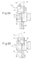
- Figs. 6A and 6B schematically show the operation modes of the wire feeding device 24, as the support unit in the umbilical-member managing system 10 of the illustrated embodiment ( Fig. 2A , Fig. 5A ), on the forearm 28, wherein Fig. 6A shows the mode of a linear motion of the slider 42 attached to the wire feeding device 24, and Fig. 6B shows the mode of a swinging motion of the slider 42.
- a linear guide rail 54 of the guide unit 44 ( Fig. 2A , Fig. 5A ) is securely provided on the forearm 28, and the slider 42 is structured to slide straight along the guide rail 54.
- the wire feeding device 24 is not illustrated, the torch cable 26 exerts, in a downward direction in the drawing, a force (by gravity) upon the slider 42 through the wire feeding device 24, as already described.
- a traction force, opposing gravity, on the torch cable 26 is exerted, in an upward direction in the drawing, through the wire feeding device 24 upon the slider 42 by the biasing mechanism 38 ( Fig. 2A , Fig. 5A ).
- the slider 42 is disposed on the guide rail 54 at a position P1 where these forces are balanced.
- the orientation of the welding torch 18 ( Fig. 2A , Fig. 5A ) changes about the second axis ⁇ and/or the third axis ⁇ as already described, the equilibrium point of these forces changes accordingly, and the slider 42 moves along the guide rail 54 to P2, P3 or another position.
- the posture of the torch cable 26 hardly varies.
- a degree of freedom of the swinging motion is given to the slider 42 by the structure of the guide unit 44 ( Fig. 2A , Fig. 5A ), in addition to the degree of freedom of a linear motion as described above (detail of the configuration is omitted).
- the orientation of the welding torch 18 Fig. 2A , Fig. 5A
- the magnitude and direction of the force exerted upon the slider 42, indirectly from the torch cable 26, will change and the slider moves to P4, P5 or another position in a swinging mode, accordingly.
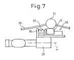
- Fig. 7 shows the configuration of a tension generating device 56 using a compression spring mechanism, as an alternative to the tension generating device 48 using a tension spring mechanism as described above.
- the tension generating device 56 includes a compression-spring support 58 formed at a desired location near a wrist on the forearm 28, and a compression spring 60 interposed in a compression state between the compression-spring support 58 and the slider 42 (or the wire feeding device 24).
- the tension generating device 56 exerts a pressing force biasing the slider 42 (or the wire feeding device 24) on the forearm 28 in a direction generally parallel to the first axis ⁇ away from the welding torch 18 ( Fig. 2A , Fig. 5A ). Therefore, when the tension generating device 56 is used in place of the tension generating device 48 as described above, the same operative effect can be achieved.
- an umbilical-member managing system for an industrial robot to automatically adjust a support position for supporting the umbilical member on a manipulator, in response to the orientation change of a working tool attached to a wrist, and thus to ensure the minimum radius of curvature allowed for the umbilical member, so as to effectively prevent the umbilical member from being excessively pulled or loosened.
- a welding wire which allows a welding operation to be performed stably and, also, an increase in life of a torch cable to be expected.
Applications Claiming Priority (2)
| Application Number | Priority Date | Filing Date | Title |
|---|---|---|---|
| JP2004071304 | 2004-03-12 | ||
| JP2004071304A JP3886497B2 (ja) | 2004-03-12 | 2004-03-12 | 産業用ロボットのための線条体処理構造 |
Publications (2)
| Publication Number | Publication Date |
|---|---|
| EP1574302A1 EP1574302A1 (en) | 2005-09-14 |
| EP1574302B1 true EP1574302B1 (en) | 2009-06-24 |
Family
ID=34824639
Family Applications (1)
| Application Number | Title | Priority Date | Filing Date |
|---|---|---|---|
| EP05004967A Expired - Fee Related EP1574302B1 (en) | 2004-03-12 | 2005-03-07 | Manipulator with an umbilical-member managing system |
Country Status (5)
| Country | Link |
|---|---|
| US (1) | US7241969B2 (ja) |
| EP (1) | EP1574302B1 (ja) |
| JP (1) | JP3886497B2 (ja) |
| CN (1) | CN1666847B (ja) |
| DE (1) | DE602005015047D1 (ja) |
Cited By (1)
| Publication number | Priority date | Publication date | Assignee | Title |
|---|---|---|---|---|
| DE202010011359U1 (de) | 2010-08-13 | 2011-02-10 | Edag Gmbh & Co. Kgaa | Dockingmodul für ein mittels eines Roboters zu handhabendes Werkzeug |
Families Citing this family (25)
| Publication number | Priority date | Publication date | Assignee | Title |
|---|---|---|---|---|
| JP4168008B2 (ja) * | 2004-06-04 | 2008-10-22 | ファナック株式会社 | 産業用ロボットの線条体処理構造 |
| EP1848571B1 (de) * | 2005-02-01 | 2008-10-08 | LEONI Kabel Holding GmbH & Co. KG | Leitungsführungseinrichtung und industrieroboter mit einer solchen einrichtung |
| KR100743611B1 (ko) * | 2006-03-28 | 2007-08-01 | 최광술 | 산업용 로봇의 케이블 조절장치 |
| KR100743612B1 (ko) * | 2006-03-28 | 2007-08-01 | 최광술 | 산업용 로봇의 케이블 조절장치 |
| JP2008229762A (ja) * | 2007-03-19 | 2008-10-02 | Fanuc Ltd | 線条体収容型アームを備えたロボット |
| US20110301733A1 (en) * | 2009-02-25 | 2011-12-08 | Panasonic Corporation | Welding method and welding system |
| DE102009010953A1 (de) | 2009-02-27 | 2010-09-02 | Dürr Systems GmbH | Roboter, insbesondere Lackierroboter |
| JP5201186B2 (ja) * | 2010-09-16 | 2013-06-05 | 株式会社安川電機 | ロボット |
| JP2012161903A (ja) * | 2011-02-09 | 2012-08-30 | Honda Motor Co Ltd | ケーブル支持装置 |
| JP5166579B2 (ja) * | 2011-08-04 | 2013-03-21 | ファナック株式会社 | 線条体の振る舞いをシミュレートするロボットシミュレーション装置 |
| CN102320040B (zh) * | 2011-08-11 | 2014-02-26 | 南昌大学 | 一种自主调节自重平衡的力反馈交互设备 |
| JP5875832B2 (ja) * | 2011-11-09 | 2016-03-02 | 和仁 鬼頭 | 多軸ロボットアーム |
| WO2014099936A1 (en) | 2012-12-18 | 2014-06-26 | Illionis Tool Works Inc. | Self-adjusting wire feeder mounting assembly and robotic mig-welding torch |
| FR3001176B1 (fr) * | 2013-01-18 | 2015-02-27 | Leoni Cia Cable Systems | Dispositif de guidage et de rappel |
| JP5895914B2 (ja) * | 2013-09-19 | 2016-03-30 | 株式会社安川電機 | ロボット |
| KR101567055B1 (ko) * | 2013-12-26 | 2015-11-09 | 디와이파워 주식회사 | 용접 와이어의 꼬임이 방지되는 용접 와이어 송급 장치 |
| USD761094S1 (en) | 2014-10-21 | 2016-07-12 | Timothy C. Hooten | Swivel device for attaching a cable to a robot |
| JP6598495B2 (ja) * | 2015-04-22 | 2019-10-30 | キヤノン株式会社 | ロボット装置、制御プログラム、記録媒体、ロボット装置の制御方法、および物品の製造方法 |
| CN104889974B (zh) * | 2015-05-14 | 2017-12-08 | 湖北骐通智能科技股份有限公司 | 机器人的线缆构造以及使用其的机器人 |
| DE102017202195A1 (de) * | 2016-03-09 | 2017-09-14 | Heidelberger Druckmaschinen Ag | Mehrachs-Roboter mit Antrieben, einem Werkzeugkopf und einer Schleppkette zum Führen von flexiblen Leitungen |
| US10543555B2 (en) | 2016-08-16 | 2020-01-28 | Lincoln Global, Inc. | Torch clamp |
| JP6730357B2 (ja) * | 2018-03-29 | 2020-07-29 | ファナック株式会社 | ロボットへの線条体追加敷設方法およびロボット |
| CN108620703B (zh) * | 2018-05-16 | 2020-12-11 | 灵璧县浩翔信息科技有限公司 | 一种建筑机械设备维修装置 |
| CN112109091B (zh) * | 2019-08-30 | 2023-01-03 | 上汽通用五菱汽车股份有限公司 | 车身零件自动上线系统及方法 |
| JP7290521B2 (ja) | 2019-09-18 | 2023-06-13 | ファナック株式会社 | ロボット用溶接ツールおよびロボット |
Family Cites Families (15)
| Publication number | Priority date | Publication date | Assignee | Title |
|---|---|---|---|---|
| US4539465A (en) * | 1983-12-30 | 1985-09-03 | Westinghouse Electric Corp. | Wire feed system for robot welder |
| IT1237707B (it) * | 1989-12-20 | 1993-06-15 | Prima Ind Spa | Struttura di macchina operatrice |
| JPH0528563A (ja) | 1991-07-18 | 1993-02-05 | Nec Corp | 光磁気記録再生方法 |
| JP2800859B2 (ja) | 1991-08-30 | 1998-09-21 | 株式会社島津製作所 | 材料試験機 |
| DE29720048U1 (de) * | 1997-11-12 | 1999-03-18 | Dinse Gmbh | Vorrichtung zum Lichtbogenschweißen |
| NZ332251A (en) * | 1998-10-09 | 2001-06-29 | Peter Carbines | Welding robot utilising gas shielded welding with power cable connected to welding electrode within a welding nozzle via slip ring assembly |
| JP2001150382A (ja) | 1999-09-09 | 2001-06-05 | Fanuc Ltd | 配線部材及び又は配管部材の案内装置、及び該装置を備えるロボット |
| US6431018B1 (en) * | 1999-09-09 | 2002-08-13 | Fanuc Ltd. | Guide device for wiring member and/or piping member and robot with guide device |
| JP3681598B2 (ja) | 1999-12-27 | 2005-08-10 | 本田技研工業株式会社 | 溶接ワイヤ供給装置の支持構造 |
| JP4274685B2 (ja) | 2000-12-04 | 2009-06-10 | 本田技研工業株式会社 | ロボットのケーブル案内装置 |
| DE20113950U1 (de) * | 2001-03-16 | 2001-11-08 | Ernst & Engbring Gmbh & Co Kg | Vorrichtung zum Führen und/oder Spannen eines Leitungsbündels bei einem Roboter |
| JP3841757B2 (ja) * | 2003-01-23 | 2006-11-01 | ファナック株式会社 | アーク溶接ロボットのトーチケーブル処理構造 |
| JP2005342859A (ja) * | 2004-06-04 | 2005-12-15 | Fanuc Ltd | 産業用ロボット |
| JP4168008B2 (ja) * | 2004-06-04 | 2008-10-22 | ファナック株式会社 | 産業用ロボットの線条体処理構造 |
| JP4653427B2 (ja) * | 2004-06-30 | 2011-03-16 | ファナック株式会社 | アーク溶接ロボットのトーチケーブル処理構造 |
-
2004
- 2004-03-12 JP JP2004071304A patent/JP3886497B2/ja not_active Expired - Fee Related
-
2005
- 2005-03-07 DE DE602005015047T patent/DE602005015047D1/de active Active
- 2005-03-07 EP EP05004967A patent/EP1574302B1/en not_active Expired - Fee Related
- 2005-03-10 CN CN2005100536876A patent/CN1666847B/zh not_active Expired - Fee Related
- 2005-03-11 US US11/076,904 patent/US7241969B2/en active Active
Cited By (1)
| Publication number | Priority date | Publication date | Assignee | Title |
|---|---|---|---|---|
| DE202010011359U1 (de) | 2010-08-13 | 2011-02-10 | Edag Gmbh & Co. Kgaa | Dockingmodul für ein mittels eines Roboters zu handhabendes Werkzeug |
Also Published As
| Publication number | Publication date |
|---|---|
| DE602005015047D1 (de) | 2009-08-06 |
| US20050199601A1 (en) | 2005-09-15 |
| JP3886497B2 (ja) | 2007-02-28 |
| EP1574302A1 (en) | 2005-09-14 |
| US7241969B2 (en) | 2007-07-10 |
| CN1666847A (zh) | 2005-09-14 |
| JP2005254404A (ja) | 2005-09-22 |
| CN1666847B (zh) | 2013-05-01 |
Similar Documents
| Publication | Publication Date | Title |
|---|---|---|
| EP1574302B1 (en) | Manipulator with an umbilical-member managing system | |
| EP1632304B1 (en) | Arc welding robot attached to a ceiling or a wall including treating torch cable structure | |
| CN110248778B (zh) | 多关节焊接机器人 | |
| JP3841757B2 (ja) | アーク溶接ロボットのトーチケーブル処理構造 | |
| EP1611988B1 (en) | Arc-welding robot with a torch cable disposition structure | |
| EP1743748B1 (en) | Guiding structure comprising a flexible tabular guide member for an umbilical member of an industrial robot | |
| CN100374235C (zh) | 电弧焊机器人的焊接炬用管线的处理构造 | |
| US4529352A (en) | Cable support of a robot | |
| US8288687B2 (en) | Arc welding robot | |
| US20080229861A1 (en) | Robot having arm in which umbilical member is accomodated | |
| EP1602460A1 (en) | Umbilical member managing system for industrial robot | |
| CN110311344B (zh) | 电缆夹以及机器人 | |
| KR102578354B1 (ko) | 천장 현수식의 산업용 로봇 | |
| JP2557404Y2 (ja) | アーク溶接ロボット | |
| JPH01306073A (ja) | ティグ溶接機ワイヤー状溶加材送り装置 | |
| JPH031197Y2 (ja) | ||
| JP2003275873A (ja) | ケーブル曲がり防止装置付き溶接ロボット | |
| JPS5936392Y2 (ja) | 自動ロ−付用工業用ロボツト |
Legal Events
| Date | Code | Title | Description |
|---|---|---|---|
| PUAI | Public reference made under article 153(3) epc to a published international application that has entered the european phase |
Free format text: ORIGINAL CODE: 0009012 |
|
| AK | Designated contracting states |
Kind code of ref document: A1 Designated state(s): AT BE BG CH CY CZ DE DK EE ES FI FR GB GR HU IE IS IT LI LT LU MC NL PL PT RO SE SI SK TR |
|
| AX | Request for extension of the european patent |
Extension state: AL BA HR LV MK YU |
|
| 17P | Request for examination filed |
Effective date: 20050912 |
|
| AKX | Designation fees paid |
Designated state(s): DE |
|
| RTI1 | Title (correction) |
Free format text: MANIPULATOR WITH AN UMBILICAL-MEMBER MANAGING SYSTEM |
|
| GRAP | Despatch of communication of intention to grant a patent |
Free format text: ORIGINAL CODE: EPIDOSNIGR1 |
|
| GRAS | Grant fee paid |
Free format text: ORIGINAL CODE: EPIDOSNIGR3 |
|
| GRAA | (expected) grant |
Free format text: ORIGINAL CODE: 0009210 |
|
| AK | Designated contracting states |
Kind code of ref document: B1 Designated state(s): DE |
|
| REF | Corresponds to: |
Ref document number: 602005015047 Country of ref document: DE Date of ref document: 20090806 Kind code of ref document: P |
|
| PLBE | No opposition filed within time limit |
Free format text: ORIGINAL CODE: 0009261 |
|
| STAA | Information on the status of an ep patent application or granted ep patent |
Free format text: STATUS: NO OPPOSITION FILED WITHIN TIME LIMIT |
|
| 26N | No opposition filed |
Effective date: 20100325 |
|
| REG | Reference to a national code |
Ref country code: DE Ref legal event code: R082 Ref document number: 602005015047 Country of ref document: DE Representative=s name: WUESTHOFF & WUESTHOFF PATENT- UND RECHTSANWAEL, DE |
|
| REG | Reference to a national code |
Ref country code: DE Ref legal event code: R081 Ref document number: 602005015047 Country of ref document: DE Owner name: FANUC CORPORATION, OSHINO, JP Free format text: FORMER OWNER: FANUC LTD., YAMANASHI, JP Effective date: 20111116 Ref country code: DE Ref legal event code: R082 Ref document number: 602005015047 Country of ref document: DE Representative=s name: WUESTHOFF & WUESTHOFF PATENT- UND RECHTSANWAEL, DE Effective date: 20111116 Ref country code: DE Ref legal event code: R081 Ref document number: 602005015047 Country of ref document: DE Owner name: FANUC CORPORATION, OSHINO-MURA, JP Free format text: FORMER OWNER: FANUC LTD., YAMANASHI, JP Effective date: 20111116 Ref country code: DE Ref legal event code: R081 Ref document number: 602005015047 Country of ref document: DE Owner name: FANUC CORPORATION, JP Free format text: FORMER OWNER: FANUC LTD., YAMANASHI, JP Effective date: 20111116 Ref country code: DE Ref legal event code: R082 Ref document number: 602005015047 Country of ref document: DE Representative=s name: WUESTHOFF & WUESTHOFF, PATENTANWAELTE PARTG MB, DE Effective date: 20111116 |
|
| REG | Reference to a national code |
Ref country code: DE Ref legal event code: R081 Ref document number: 602005015047 Country of ref document: DE Owner name: FANUC CORPORATION, OSHINO, JP Free format text: FORMER OWNER: FANUC CORP., YAMANASHI, JP Effective date: 20120202 Ref country code: DE Ref legal event code: R082 Ref document number: 602005015047 Country of ref document: DE Representative=s name: WUESTHOFF & WUESTHOFF PATENT- UND RECHTSANWAEL, DE Effective date: 20120202 Ref country code: DE Ref legal event code: R081 Ref document number: 602005015047 Country of ref document: DE Owner name: FANUC CORPORATION, OSHINO-MURA, JP Free format text: FORMER OWNER: FANUC CORP., YAMANASHI, JP Effective date: 20120202 Ref country code: DE Ref legal event code: R081 Ref document number: 602005015047 Country of ref document: DE Owner name: FANUC CORPORATION, JP Free format text: FORMER OWNER: FANUC CORP., YAMANASHI, JP Effective date: 20120202 Ref country code: DE Ref legal event code: R082 Ref document number: 602005015047 Country of ref document: DE Representative=s name: WUESTHOFF & WUESTHOFF, PATENTANWAELTE PARTG MB, DE Effective date: 20120202 |
|
| PGFP | Annual fee paid to national office [announced via postgrant information from national office to epo] |
Ref country code: DE Payment date: 20220203 Year of fee payment: 18 |
|
| REG | Reference to a national code |
Ref country code: DE Ref legal event code: R119 Ref document number: 602005015047 Country of ref document: DE |
|
| PG25 | Lapsed in a contracting state [announced via postgrant information from national office to epo] |
Ref country code: DE Free format text: LAPSE BECAUSE OF NON-PAYMENT OF DUE FEES Effective date: 20231003 |