EP1574291A2 - Spann- und Spreizvorrichtung - Google Patents
Spann- und Spreizvorrichtung Download PDFInfo
- Publication number
- EP1574291A2 EP1574291A2 EP05003716A EP05003716A EP1574291A2 EP 1574291 A2 EP1574291 A2 EP 1574291A2 EP 05003716 A EP05003716 A EP 05003716A EP 05003716 A EP05003716 A EP 05003716A EP 1574291 A2 EP1574291 A2 EP 1574291A2
- Authority
- EP
- European Patent Office
- Prior art keywords
- clamping
- spreading device
- slide rail
- spreading
- displacement
- Prior art date
- Legal status (The legal status is an assumption and is not a legal conclusion. Google has not performed a legal analysis and makes no representation as to the accuracy of the status listed.)
- Granted
Links
Images

Classifications
-
- B—PERFORMING OPERATIONS; TRANSPORTING
- B25—HAND TOOLS; PORTABLE POWER-DRIVEN TOOLS; MANIPULATORS
- B25B—TOOLS OR BENCH DEVICES NOT OTHERWISE PROVIDED FOR, FOR FASTENING, CONNECTING, DISENGAGING, OR HOLDING
- B25B5/00—Clamps
- B25B5/06—Arrangements for positively actuating jaws
-
- B—PERFORMING OPERATIONS; TRANSPORTING
- B25—HAND TOOLS; PORTABLE POWER-DRIVEN TOOLS; MANIPULATORS
- B25B—TOOLS OR BENCH DEVICES NOT OTHERWISE PROVIDED FOR, FOR FASTENING, CONNECTING, DISENGAGING, OR HOLDING
- B25B5/00—Clamps
- B25B5/06—Arrangements for positively actuating jaws
- B25B5/068—Arrangements for positively actuating jaws with at least one jaw sliding along a bar
Definitions
- the invention relates to a tensioning and spreading device with a displaceable mounted slide, whose displacement movement in a clamping direction can be actuated with blocking the abduction in the opposite direction and whose displacement movement can be actuated in a spreading direction with Locking the displaceability in the opposite direction, the direction of displacement can be switched between the clamping direction and spreading direction.
- tensioning and spreading device is for example from the WO01 / 56747 A1. Clamping and spreading are also from the US 4257 584 and US 5,593,147.
- the invention is based on the object, a tensioning and spreading to provide the type mentioned, which can be produced in a simple manner and is easy to use.
- the movable and in particular displaceable positioning (which may be formed in one or more parts) can be the actuators position so that the slide rail is in the tightening direction or can be moved in the spreading direction. It breaks up a simple way a switchability for the shift operation of the Implement slide between clamping direction and spreading direction.
- a single handle lever on the actuators to act, so that a single lever handle a shift operation possible in the clamping direction and in the spreading direction is.
- the handle lever can be easily arranged so that at a pivoting movement in a single direction depending on the position of the positioning a shift of the slide in the clamping direction or Spreading takes place.
- a Free to arrange handle lever In particular, it can be arranged so that the tensioning and spreading device has reduced dimensions. He let Also arrange so that the tensioning and spreading device can be operated with one hand is. For example, it is possible to arrange the handle lever so that he to be pivoted to the sliding to the shift operation can. He is then not laterally on the tensioning and spreading out. This also allows easy handling of the clamping and Reach spreading device.
- the movable positioning is the assembly of the clamping and Spreading simplified during manufacture.
- the number of components can be kept low. For example, it is possible only two actuators to be provided, which also serve as locking elements for the slidability in the opposite direction of an actuating element associated displacement direction can act.
- the positioning element in the displacement direction of the slide rail displaced. It can then be on the slide a shift guide provide so that no separate displacement guide must be formed within a housing.
- the positioning element on the Sliding rail is mounted and in particular displaceable on the slide rail is.
- a first one for the positioning Position is provided, in which the displacement of the slide rail in the Spreading is actuated.
- the first position is excellent Position.
- the positioning element is arranged so that just just a shift operation of the slide in the spreading is possible.
- the displaceability of the slide rail in the Opposite direction (the clamping direction) locked.
- the first position can be fixed, for example by latching. This makes the first position an excellent position defined and this is adjustable for an operator in a defined manner.
- the positioning element can also be part of the Switching device be. If a switch takes place, then that will Moving positioning in a position (in particular the first Position or the second position), in which the slide rail only in the spreading direction or is displaceable only in the clamping direction.
- the positioning via the switching device can be brought into a first position, in which the slide rail in the spreading direction is displaceable, and in a second position can be brought, in which the Slide rail is displaceable in the clamping direction. This allows the direction of displacement switch over via the positioning element.
- a tensioning and spreading device can be easily Establish way when the switching device is a mechanical switch has, which is coupled to the positioning element.
- the switching device is a mechanical switch has, which is coupled to the positioning element.
- this mechanical Switch can move the positioning and in particular move.
- a rotary switch can be provided, which is so is arranged and configured and is thus coupled to the positioning element, that a rotational movement of the mechanical switch in a Translational movement of the positioning is feasible.
- an actuating element as a blocking element to block the mobility of the slide in the opposite direction formed of the actuating element associated displacement direction is. This allows the number of parts for the displacement mechanism and locking mechanism of the tensioning and spreading device according to the invention minimize. Furthermore, this leaves the corresponding device also form compact and space-saving, in addition to the actuators no separate locking elements must be provided.
- At least one contact surface is provided in order to Hold blocking element in a locked position.
- a blocking element can be held in a tilted position the displacement of the slide rail in the released direction allowed, and the mobility in the opposite direction locks. Over the contact surface leaves hold the blocking element in its blocking position (tilted position).
- an actuating element at least one return spring assigned.
- a force is applied to an actuator is, then, for example, such a return spring is compressed.
- the actuator is in its original Position reset, so that a renewed operation is feasible.
- This also makes it possible for a pivoting lever (handle lever) is pivoted back to its original position.
- the actuator associated with at least one Return spring disposed on the positioning, wherein the positioning element is advantageously designed as a spring cage.
- the movable positioning element then provides for a provision in its excellent positions of the respective actuating element.
- the positioning element holds a first actuating element for actuating the displacement movement of the slide rail in the Tensioning direction.
- the first actuating element as a blocking element for the displaceability in the spreading direction acts.
- the positioning element holds a second actuating element Actuation of the displacement guide of the slide in the spreading direction. It is then also favorable if the second actuating element as a blocking element acts for the mobility of the slide in the clamping direction.
- the number of components required can be kept low. Thereby in turn, the clamping and spreading device according to the invention can be build compact and easy to manufacture.
- first actuating element and the second Actuator arranged at least one spring.
- a spring Preferably is between the first actuating element and the second actuating element arranged on both sides of the slide a spring. additionally can still have a spacer element between the two actuators be arranged.
- the spacer element can also serve as a spring guide, which is the mounting of the positioning simplified as a spring cage with actuators.
- a handle lever for actuating the displacement of the slide at least provided a handle lever.
- This handle lever which in one piece or may be formed in several parts, acts on the corresponding actuators, to tilt this with the slide and then for a Forward thrust.
- an actuating element tiltable and movable to take the slide rail to move can via the at least one handle lever is an actuating element tiltable and movable to take the slide rail to move can.
- a single handle lever which is arranged and designed so that it depends on the position of the positioning to a first actuating element for displacement of the slide rail in the tensioning direction or on a second actuating element for displacement the slide acts in the spreading direction.
- the movable Positioning element is sufficient a single handle lever to the displacement of the Operating slide in the clamping direction and in the spreading direction. about Movement and in particular displacement of the positioning is included switchable between these two directions. It can then be the inventive Compact construction of clamping and spreading device. Since only one only handle must be provided, the footprint can be low hold.
- the handle lever can in turn be arranged so that the inventive Clamping and spreading device easy to operate and in particular one-handed operation. Furthermore, this is also the production simplified.
- the first actuating element and the second actuator depending on the position of the positioning in opposite directions Tiltable (and movable) directions.
- tilting in opposite directions and corresponding tilting and movement can be about the respective actuator, the slide in the one Direction or in the other direction (opposite direction).
- the at least one handle lever via a stub shaft stub shank bearing pivotable on a housing is stored.
- the handle lever can be doing starting from an (inner) Store the surface of the housing so that no shaft passes through the housing got to. There must be no appropriate place for such a place Wave be provided. As a result, the assembly is simplified and leaves it to achieve a compact structure.
- the stub shaft stub shank bearing is arranged above the positioning element. Thereby can then corresponding lever tabs of the handle lever in a simple manner access the actuators, thereby in turn by the Actuators to move the slide can.
- the at least one handle lever is arranged and formed is that when pivoting on the slide to a shift the slide rail is actuated. This results in a simple Operability. In particular, a one-hand operation can be realized, if a corresponding counter-grip element is provided.
- the at least one handle lever when not in use, sits at an acute angle to the slide rail.
- This angle is, for example, in the order of 40 °.
- An operator can then grasp the handle lever and a counter-grip element with one hand and the handle lever in the direction of the slide rail (in the direction of the counter-grip element) pivot, so as to actuate the displacement of the slide rail.
- the Positioning of the positioning is the direction of displacement of the Slide rail adjusted.
- the slide rail is mounted displaceably in the counter-grip element.
- About the counter-grip element can then be another shift bearing for provide the slide to store this largely free of play can.
- a release element (release lever) is provided, via which a blocking element can be brought into a non-locking position is.
- the release element may be formed in one or more parts. In the Practice often occurs on the case that the slide moved over longer distances must be and such a shift on the actuators too time consuming. About the release element can directly on each acting blocking element are accessed and this can be solved and an operator can then move the slide by hand. Farther can a clamping position of the device (with clamped workpiece) be solved.
- the release element is designed so that it depends on the Position of the positioning on the respective locking element acts. Thereby it is achievable that the release element just on the relevant blocking element acts. An operator can then slide the slide independently solve whether an operability of the slide in the clamping direction or in Spreading is set.
- the release element arranged pivotally.
- the release element is designed as a release lever. By pivoting can be acted on a blocking element so, that its blocking effect is canceled.
- the release element on a handle lever for actuating the Swiveling the slide rail stored. This can be reduced to simple and Space-saving way form a corresponding pivot bearing.
- the release element is arranged and designed such that a Pivoting direction for releasing regardless of the position of the positioning is. This simplifies operation.
- the housing can be the sliding mechanism and Pick up locking mechanism for the slide rail. This is housed there protected.
- the positioning element is guided in the housing, so that it is flat is protected in its displaceability from external influences.
- a housing cover is provided. This allows the assembly the tensioning and spreading device according to the invention during manufacture simplify.
- the housing is designed so that the moving parts for the displacement mechanism can be inserted.
- the corresponding Contact surfaces and receiving areas are preferably integral made in the corresponding housing part. The mechanics can then be inserted Be without additional elements such as pen shafts or the like must be provided.
- the assembly is greatly simplified. about a housing cover, which is fixed to the rest of the housing, can be then close the case.
- a contact element for workpieces is connected to the housing.
- This investment element may be a separate part, which with the Housing is connected. But it can also be a one-piece to the Housing formed investment element act.
- a contact element for workpieces is connected to the slide rail. This contact element sits in particular firmly on the slide rail. Between The two contact elements can then clamp workpieces, if these are moved towards each other. If the attachment elements from each other be moved away, then can be appropriate spreading forces on workpieces exercise.
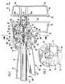
- FIG Part-sectional view shown and designated there as a whole with 10.
- the clamping and Spreading device 10 has a slide rail 12, which in a Longitudinal direction 14 extends.
- the slide rail 12 is profiled ( Figure 3). She points on opposite long sides dents 16a, 16b on.
- the slide rail 12 is preferably made of a metallic material.
- a contact element 20th arranged for workpieces.
- This contact element 20 is in particular fixed with the slide rail 12 is connected. It can be provided that the contact element 20 is releasably fixed to the slide rail 12 or fixedly fixed to this is.
- the contact element 20 may be integrally formed on the slide rail 12 or it may be a separate element, which subsequently the slide rail 12 is fixed.
- the contact element 20 is made made of a plastic material.
- the contact element 20 has a first contact surface 22.
- This first contact surface 22 is preferably flat.
- the contact surface 22 is based on opposite short sides 24a, 24b of the slide rail over this out, so that a workpiece above or below the slide rail 12th can be applied.
- the contact element 20 has a further second contact surface 26, which the first contact surface 22 is opposite.
- the second contact surface 26 is here an outer surface. This second contact surface 26 is preferably flat.
- the slide rail 12 is slidably mounted in a housing 28 and in particular slidably mounted. Relative to this housing 28 is the slide rail 12 parallel to its longitudinal direction in a clamping direction 30 and in a spreading 32 slidably.
- the spreading direction 32 is the opposite direction to the clamping direction 30 and the clamping direction 30 is the opposite direction to the spreading direction 32nd
- a contact element 34 is connected, which is a first Contact surface 36 has for workpieces.
- the first contact surface 36 of the contact element 34 indicates the first contact surface 22 of the contact element 20, so that between the contact surfaces 22, 36 one or more workpieces can be clamped are.
- the first contact surface 36 is in particular substantially just trained and extends over both sides 24a, 24b of the slide rail 12 out.
- the first contact surface 36 is in its shape in the essentially the same design as the first contact surface 22 of the contact element 20th
- the contact element 34 also has a second contact surface 38, which the first contact surface 36 is opposite.
- This second contact surface 38 is in particular substantially flat.
- the second abutment element 34 may be integrally connected to the housing 28 be.
- the housing 28 with integrated contact element 34 is made made of a plastic material. It is also possible in principle that the abutment element 34 is a separate part from the housing 28, which is fixed to the housing 28 during manufacture.
- the contact element 20 is relative to the contact element 34 (and thus to the housing 28) displaceable, wherein in the displacement of the slide in the clamping direction 30, the contact element 20 on the contact element 34 (on the housing 28) is moved to and upon displacement of the slide in the spreading direction 32, the contact element 20 is moved away from the abutment member 34 (the housing 28).
- the housing 28 is aligned aligned bearings 40, 42 and 44 on. Through these bearings 40, 42, 44 passes through the slide rail 12 and is slidably guided.
- the Bearings 40, 42, 44 have such to the dimensions of the slide rail 12th matched dimensions, that the slide rail 12 is substantially free of play is held on the housing 28 while sliding on the housing 28 is guided.
- the bearing 40 is, for example, by a recess in the contact element 34 formed.
- the bearing 44 is formed by a recess in a Counter-grip element 46 is formed.
- the bearings 40, 44 lie on or in the vicinity of opposite frontal ends of the housing 28.
- Die Bearing 42 is between the bearings 40 and 44 in the housing 28th formed to provide additional support of the slide rail 12.
- the housing 28 In the housing 28 is a displacement mechanism and locking mechanism for recorded the displacement operation of the slide rail 12.
- the housing 28 has a shell-like area 48, which the corresponding Parts absorbs.
- About a housing cover 50 ( Figure 3) is this shell-like Area 48 closed.
- the housing 28 is preferably formed so that the displacement mechanism and locking mechanism for the slide rail 12 in the housing 28th can be positioned without additional fastening screws provided must be or that other components (such as investment pens or waves) must be provided.
- a positioning element 52 is movable and in particular slidably guided, wherein the displacement direction parallel to the displacement direction the slide rail 12 is.
- the positioning element 52 can be in the clamping direction 30 and the spreading direction 32 move.
- the positioning element can be formed in one piece or multiple parts.
- the positioning element 52 sits on the Slide rail 12 and is guided on this sliding.
- the slide rail 12th thus provides a guideway for the positioning element 52, so that no additional guide track in the housing 28 must be provided.
- the positioning element 52 has two excellent positions, namely a first position 54 in which the positioning element 52 farthest in the clamping direction 30 is shifted.
- This first position 54 is in FIG. 1 indicated by dashed lines.
- In this first position 54 is the Positioning element 52 at or near the bearing 42nd
- a second position 56 which is shown in Figure 1 in solid lines is the positioning member 52 in the housing 28 furthest in the Spreading 32 shifted.
- the positioning element 52 is in FIG his first position 54 shown.
- One end 58 of the positioning element 52, which faces the contact element 20 is then closest to the Bearing 40.
- a the end 58 opposite end 60 of the positioning 52 has in the second position 56 the largest distance to the bearing point 42. Accordingly, in the first position 54, the end 58 has the largest Distance to the bearing 40 and the end 60 has the smallest Distance to the bearing 42 on.
- the displacement movement of the positioning member 52 on the slide rail 12 is actuated via a switching device 62, wherein, as below is described in more detail, via the switching device 62 between a shift the slide rail 12 in the spreading direction 32 with blocking the mobility in the opposite direction 30 and a slidability of the slide rail 12 in the clamping direction 30 with blocking the mobility in the Counter direction 32 is switchable. Switching is done by positioning of positioning element 52 in positions 54 and 56.
- the switching device 62 comprises in the illustrated embodiment a rotary switch 64 (FIGS. 1 and 2) which is rotatable in the housing 28 is stored.
- This rotary switch 64 has an eccentrically arranged pin 66, which is immersed in a recess 68 of the positioning member 52 is.
- the recess 68 is transverse and in particular perpendicular to the longitudinal direction 14 of the slide rail 12 oriented (and thus transversely to the Directions 30 and 32).
- the engagement of the eccentrically arranged pin 66 in the recess 68 can be a rotational movement of the rotary switch 64 in a linear displacement movement implement the positioning member 52 so in particular the positioning element 52 starting from its first position 54 in the second position 56 to move and starting from the second Position 56, the positioning member 52 in the first position 54 bring can.
- the pin 66 is in the first position 54 (FIG. 2). further away from the bearing 40 than in the second position 56 ( Figure 1) of Positioning element 52nd
- the rotary switch 64 is preferably in relation to the recess 68 designed so that just the first position 54 and the second position 56 excellent Positions are, which are fixable. For example, this is the Rotary switch 64 locked when the first position 54 is reached or if the second position 56 is reached. It can also be provided that the Rotary switch 64 is formed in relation to the recess 68 so that he can not be further rotated when the first position 54 is reached, that is, starting from the first position 54, only one rotational movement in an opposite direction is possible to the positioning member 52 from the first Release position 54. Similarly, it is then beneficial if it is provided that the rotary switch 64 is no longer rotated can be when starting from the first position 54, the second position 56 is reached. It is then only a counter rotation possible to the positioning 52 from the second position 56 in the first position 54 to bring can.
- the positioning member 52 holds a first operating member 70 and a second actuator 72.
- a Displacement actuation of the slide rail 12 in the clamping direction 30 allows and via the second actuator 72 is a shift operation allows the slide rail 12 in the spreading direction 32.
- the return springs 74a, 74b are based on a region of the positioning element 52, which at or near the end 60 is located.
- the actuators 70, 72 are preferably metallic parts which a respective recess 78 ( Figure 3), with which they on the positioning 52 are arranged on the slide rail 12. Upon movement of the positioning element 52, the actuators 70, 72 are moved along.
- the actuating elements 70, 72 are in particular plate-shaped. You are against the slide rail 12 tilted or tilted and with the Slide rail 12 can be tilted. Depending on the tilting direction and force application is by the actuators 70, 72, the movement of the slide rail 12 causes in a direction of displacement and in the opposite direction blocked. This will be explained in more detail below.
- the first actuating element 70 serves for the displacement actuation of the slide rail 12 in the clamping direction 30.
- the second actuator 72 is used to the shift operation of the slide rail 12 in the spreading direction 32nd Whether the actuator 70 acts on the slide rail 12 or the actuator 72 acts on the slide rail 12 is determined by the position of the positioning 52 set. In the first position 54, the second Tilt actuator 72 so that over the corresponding tilting and movement of the actuator 72, the slide rail 12 taken is moved and in the spreading direction 32. In the second position 56 of the positioning element 52, the first actuating element 70 can thus tilt and tilt with the slide and move that the slide rail 12 is taken in the clamping direction 30.
- the first actuating element 70 is a locking element, which is the displaceability the slide 12 locks in the clamping direction 30 and the mobility in the spreading direction 32 releases when the positioning member 52 in his first position is 54.
- the second actuating element 72 a blocking element, which is the displaceability of the slide rail 12 in the Sp Schwarzraum 32 locks and the mobility in the clamping direction 30th releases when the positioning member 52 is in the second position 56.
- the first actuator 70 may act as a blocking element is in the housing 28, a contact surface 80 is provided, on which the first Actuator 70 in the first position 54 of the positioning member 52nd can be applied, so as to provide a tilting of the actuating element 70, the just a displaceability of the slide rail 12 in the clamping direction 30th locks.
- a contact surface 82 for the second actuator 72 provided when this second actuator 72nd acts as a blocking element when the positioning element 52 in the second position 56 is.
- the second actuator 72 can be applied, to provide such a tilt, which is a displaceability of Slide rail 12 in the spreading direction 32 locks (while the shift the slide rail 12 in the clamping direction 30 allows).
- the actuators 70, 72 in opposite Directions are tilted. Accordingly, the contact surfaces are 80, 82, based on the slide rail 12, on (diagonally) opposite Pages in the housing 28.
- the contact surfaces 80, 82 can be at the manufacture of the housing 28 integrally form.
- the two actuating elements 70, 72 are spaced at the positioning element 52 arranged. On the positioning element 52 sits a spacer 84 between these two actuators 70 and 72nd
- the two actuating elements 70, 72 are in turn supported by a first Spring 86 and a second spring 88 against each other, wherein the springs 86, 88th are arranged on opposite sides with respect to the slide rail 12.
- the spacer 84 has corresponding recesses through which the Pass springs 86, 88.
- the springs 86, 88 allow for exertion of force on one of the actuators 70, 72 a relative tiltability to each other with resetting effect when the exercise is over.
- a handle lever 90 as Gripping element provided with a handle portion 92.
- the grip element 90 is pivotally mounted on the housing 28.
- the grip element 90 a stub shaft 94, which in a particular one piece on the Housing cover 50 formed stub shaft receptacle 96 is located so that a Stub shaft stub shank bearing 98 is formed.
- the bearing 98 is relative to a direction of one Housing interior to the outside (transverse to the slide rail 12) above the Positioning element 52 is arranged.
- the handle member 90 is formed so that it depending on the position of the positioning 52 acts on either the first actuator 70 or on the second actuator 72 acts to either a displacement in the Clamping direction 30 (second position 56 of the positioning member 52) or a Displacement in the spreading direction 32 (first position 54 of the positioning 52).
- the grip element 90 in an inside of the housing 28 arranged portion 100 of the handle member 90 has a first Tab 102, which can act on the first actuator 70 to this tilt in the direction of the bearing 42 and in the spreading direction 32 to move and thus the displacement of the slide rail 12 in the clamping direction 30 to effect; Furthermore, it has a second tab 104, which can act on the second actuator 72 to this in the direction of Store to tip 40 and move in the clamping direction 30 and thus to cause a displacement of the slide rail 12 in the spreading direction 32.
- the second tab 104 is arranged so that it is on the actuating element 72 of the side 24b of the slide rail 12 facing and acts on it one side of the second actuating element 72 acts which of the contact surface 36 turned away.
- the first tab 102 is thus arranged on the grip element 90, that it acts on the first actuator 70 in an area which faces the side 24a of the slide rail 12. Furthermore, the first one works Tab 102 on a portion of the first actuating element 70, which of the Bearing surface 36 faces. This can be achieved by a pivoting movement the handle member 90 in a pivoting direction 106 depending on the position of the Positioning element 52 is a shift in the clamping direction 30 or in the Reach opposite direction 32. Whether the handle element 90 with its first tab 102 acts on the first actuator 70 or with its second tab 104 acts on the second actuator 72, in turn depends on the displacement position of the positioning element 52 from. In the second Position 56, the gripping element 90 acts on the first actuating element 70, while in the first position 54 of the positioning member 52, the second Tab 104 acts on the second actuator 72.
- the grip element 90 with the handle portion 92, the area 100 and the tabs 102 and 104 and the stub shaft 94 is integrally formed and in particular made of a plastic material is.
- the handle portion 92 of the handle member 90 is formed so that it from a User's hand with the fingers or the palm of the hand can be grasped.
- a non-pivoted position is in the illustrated embodiment the handle portion 92 at an acute angle to the longitudinal direction 14 of Slide rail 12 is arranged. This angle can, for example, in a Order of magnitude of 40 °.
- a pivoting movement in the Pivoting direction 106 on the slide 12 can be the respective, about the position of the positioning element 52 selected actuator 70, Apply 72 force.
- the counter-grip element 46 which in particular integrally with the housing 28 is formed, is just a counter-grip element for the handle portion 92 of the Gripping element 90.
- the angular position of the handle portion 92 is just such that a user, the counter-grip member 46 and the handle portion 92 with a Can hold hands, so that the clamping and spreading device according to the invention 10 is operated with one hand.
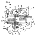
- a release element 108 which is pivotable in the Housing 28 is arranged.
- it is pivotally mounted on the handle element 90.
- a corresponding pivot bearing. about a recess 110 in the housing 28 may be a user on the release element access and move this.
- the release element 108 has a first tab 112, with which it on the second actuator 72 may act on one side of the actuator 72, which faces the contact surface 36. Further points the release element 108 a second tab 114, with which it on the first Actuator 70 may act, on a side which of the contact surface 36 turned away.
- the first tab 112 of the release element 108 is located the second tab 104 of the handle member 90 opposite. Through the release element can the second actuator 72 from a Verkippungs sued to solve. The same applies to the first actuating element 70 via the Tab 114.
- Through the release element can be a blocking position of the corresponding Actuator 70 or 72, when it is in a locked position, be repealed to move the slide 12 "by hand” can or a clamping position or spread position with respect to workpieces to be able to solve.
- the actuator 70 in Direction of the contact surface 36 are tilted to cancel the blockage.
- the release element 108 is in particular formed in one piece.
- the tabs 112, 114 are relative to the slide rail 12 on opposite Pages. As a result, by a pivoting movement in one direction a Solution of the slide can be achieved, regardless of whether the positioning element 52 in its first position 54 or in its second position 56 is.
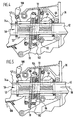
- the rotary switch 64 of the switching device 52 is in such a position the positioning element 52 is in its second position 56 (FIG. 4).
- the second actuating element 72 abuts against the associated contact surface 82 and is tilted relative to the slide rail 12. This is the mobility the slide rail 12 is locked in the spreading direction 32.
- the first actuator 70 is in such a position that a displaceability in the Clamping direction 30 is released. Basically, by pressing the slide rail 12 in the tensioning direction 30 this moved in the clamping direction 30 become.
- the grip element 90 with the first tab 102 act on the actuator 70, in order for a driving of the slide rail 12 in the clamping direction 30 to care.
- FIG. 5 shows a position in which the grip element 90 is related to a starting position in the direction of the slide rail 12 is pivoted.
- the first tab 102 of the handle member 90 acts on the first actuator 70 and tilts and moves this.
- the springs 74a, 74b pressed together. Due to the tilting and movement of the actuator 70, the slide rail 12 is taken in the clamping direction 30 (While the actuator 72, the displaceability in the opposite direction 32 blocks).
- the springs 86, 88 between the two actuators 70, 72 ensure that just a tilt or tilting of the actuator 70 is allowed to take along the slide rail 12.
- the restoring force causes the springs 74a, 74b that the handle member 90 returns to its original position.
- the first actuator 70 then returns to its in the Figure 4 shown starting position back, but with the slide rail 12 to a corresponding piece is displaced in the clamping direction 30.
- the positioning element 52 starting from the second position 56 in the first position 54th be moved and in this position 54, for example by locking be fixed.
- the ratios compared to those explained in Figures 4 to 6 Case turn around in that now the first actuator 70th acts as a blocking element and the handle element 90 on the second actuating element 72 is acted on the shift operation.
- the release element 108 the blocking effect of the first actuating element 70 can be cancel.
- the operation is basically the same as above based on the second position 56 described.
- the tensioning and spreading device 10 can be easily Make way. The number of parts needed can be kept low.
- the Displacement and locking mechanism can be mounted easily.
- the positioning element 52 which in particular designed as a spring cage is, can be between a spreading or a clamping operation switch accordingly by the positioning member 52 in the first Position 54 or in the second position 56 is positioned.
- the shift on the slide 12 can be easily between them Switch positions 54 and 56.
- a single handle member 90 can be (depending on the position of the positioning 52) perform either a spreading or a clamping operation.
- a single handle member 90 with a single pivot actuation direction can the slide 12 is either in the clamping direction 30th or move in the spreading direction 32.
- the arrangement of the handle member 90 with respect to the slide is in principle freely selectable, so that an optimized ergonomic design is possible.
- a counter-grip element (the counter-grip element 46) can be align along the slide rail 12. This in turn makes it possible for the Slide rail 12 in the mating handle member 46 for the Gleitverschiebrete to store.
Landscapes
- Engineering & Computer Science (AREA)
- Mechanical Engineering (AREA)
- Clamps And Clips (AREA)
- Seats For Vehicles (AREA)
- Mechanisms For Operating Contacts (AREA)
Abstract
Description
- Figur 1
- eine Teil-Schnittansicht eines Ausführungsbeispiels einer erfindungsgemäßen Spann- und Spreizvorrichtung;
- Figur 2
- eine vergrößerte Darstellung des Bereichs A gemäß Figur 1;
- Figur 3
- eine Schnittansicht der Spann- und Spreizvorrichtung gemäß Figur 1 längs der Linie 3-3;
- Figur 4
- eine Teil-Schnittansicht von mechanischen Elementen zur Bewegung einer Gleitschiene der Spann- und Spreizvorrichtung gemäß Figur 1 bei unverschwenktem Griffhebel;
- Figur 5
- die gleiche Ansicht wie Figur 4 in einem Momentbild während der Verschwenkung eines Griffhebels und
- Figur 6
- die gleiche Ansicht wie Figur 4 und 5 als Momentaufnahme während der Schwenkbewegung eines Löseelements.
Claims (44)
- Spann- und Spreizvorrichtung mit einer verschieblich gelagerten Gleitschiene (12), deren Verschiebungsbewegung in einer Spannrichtung (30) betätigbar ist mit Sperrung der Verschieblichkeit in die Gegenrichtung (32) und deren Verschiebungsbewegung in einer Spreizrichtung (32) betätigbar ist mit Sperrung der Verschieblichkeit in die Gegenrichtung (30), wobei die Verschiebungsrichtung (30, 32) zwischen Spannrichtung (30) und Spreizrichtung (32) umschaltbar ist,
dadurch gekennzeichnet, daß ein bewegliches Positionierelement (52) vorgesehen ist, welches Betätigungselemente (70, 72) für die Gleitschiene (12) hält, wobei in Abhängigkeit von der Position (56; 54) des Positionierelements (52) die Verschiebungsbewegung der Gleitschiene (12) in die Spannrichtung (30) oder in die Spreizrichtung (32) betätigbar ist. - Spann- und Spreizvorrichtung nach Anspruch 1, dadurch gekennzeichnet, daß das Positionierelement (52) in Verschiebungsrichtung (30, 32) der Gleitschiene (12) verschieblich ist.
- Spann- und Spreizvorrichtung nach Anspruch 1 oder 2, dadurch gekennzeichnet, daß das Positionierelement (52) an der Gleitschiene (12) gelagert ist.
- Spann- und Spreizvorrichtung nach einem der vorangehenden Ansprüche, dadurch gekennzeichnet, daß das Positionierelement (52) auf der Gleitschiene (12) verschieblich ist.
- Spann- und Spreizvorrichtung nach einem der vorangehenden Ansprüche, dadurch gekennzeichnet, daß für das Positionierelement (52) eine erste Stellung (54) vorgesehen ist, in welcher die Verschiebung der Gleitschiene (12) in der Spreizrichtung (32) betätigbar ist.
- Spann- und Spreizvorrichtung nach Anspruch 5, dadurch gekennzeichnet, daß die erste Stellung (54) fixierbar ist.
- Spann- und Spreizvorrichtung nach einem der vorangehenden Ansprüche, dadurch gekennzeichnet, daß für das Positionierelement (52) eine zweite Stellung (56) vorgesehen ist, in welcher die Verschiebung der Gleitschiene (12) in der Spannrichtung (30) betätigbar ist.
- Spann- und Spreizvorrichtung nach Anspruch 7, dadurch gekennzeichnet, daß die zweite Stellung (56) fixierbar ist.
- Spann- und Spreizvorrichtung nach einem der vorangehenden Ansprüche, dadurch gekennzeichnet, daß eine Bewegung des Positionierelements (52) über eine Umschalteinrichtung (62) zur Umschaltung der Bewegungsrichtung (30, 32) der Gleitschiene (12) betätigbar ist.
- Spann- und Spreizvorrichtung nach Anspruch 9, dadurch gekennzeichnet, daß über die Umschalteinrichtung (62) das Positionierelement (52) in eine erste Stellung (54) bringbar ist, in welcher die Gleitschiene (12) in der Spreizrichtung (32) verschieblich ist, und in eine zweite Stellung (56) bringbar ist, in welcher die Gleitschiene (12) in der Spannrichtung (30) verschieblich ist.
- Spann- und Spreizvorrichtung nach Anspruch 9 oder 10, dadurch gekennzeichnet, daß die Umschalteinrichtung (62) einen mechanischen Schalter (64) aufweist, welcher an das Positionierelement (52) gekoppelt ist.
- Spann- und Spreizvorrichtung nach einem der vorangehenden Ansprüche, dadurch gekennzeichnet, daß ein Betätigungselement (70; 72) als Sperrelement zur Sperrung der Verschieblichkeit in der Gegenrichtung (32; 30) zu der dem Betätigungselement (72; 70) zugeordneten Verschiebungsrichtung (30; 32) ausgebildet ist.
- Spann- und Spreizvorrichtung nach Anspruch 12, dadurch gekennzeichnet, daß mindestens eine Anlagefläche (80; 82) bereitgestellt ist, um ein Sperrelement (70; 72) in einer Sperrposition zu halten.
- Spann- und Spreizvorrichtung nach einem der vorangehenden Ansprüche, dadurch gekennzeichnet, daß einem Betätigungselement (70; 72) mindestens eine Rückstellfeder (74a; 74b; 76) zugeordnet ist.
- Spann- und Spreizvorrichtung nach Anspruch 14, dadurch gekennzeichnet, daß die dem Betätigungselement (70; 72) zugeordnete mindestens eine Rückstellfeder (74a, 74b; 76) am Positionierelement (52) angeordnet ist.
- Spann- und Spreizvorrichtung nach Anspruch 15, dadurch gekennzeichnet, daß das Positionierelement (52) als Federkäfig ausgebildet ist.
- Spann- und Spreizvorrichtung nach einem der vorangehenden Ansprüche, dadurch gekennzeichnet, daß das Positionierelement (52) ein erstes Betätigungselement (70) zur Betätigung der Verschiebungsbewegung der Gleitschiene in der Spannrichtung (30) hält.
- Spann- und Spreizvorrichtung nach Anspruch 17, dadurch gekennzeichnet, daß das erste Betätigungselement (70) als Sperrelement für die Verschieblichkeit der Gleitschiene (12) in der Spreizrichtung (32) wirkt.
- Spann- und Spreizvorrichtung nach einem der vorangehenden Ansprüche, dadurch gekennzeichnet, daß das Positionierelement (52) ein zweites Betätigungselement (72) zur Betätigung der Verschiebungsbewegung der Gleitschiene (12) in die Spreizrichtung (32) hält.
- Spann- und Spreizvorrichtung nach Anspruch 19, dadurch gekennzeichnet, daß das zweite Betätigungselement (72) als Sperrelement für die Verschiebung der Gleitschiene (12) in die Spannrichtung (30) wirkt.
- Spann- und Spreizvorrichtung nach Anspruch 19 oder 20, dadurch gekennzeichnet, daß zwischen dem ersten Betätigungselement (70) und dem zweiten Betätigungselement (72) mindestens eine Feder (86, 88) angeordnet ist.
- Spann- und Spreizvorrichtung nach Anspruch 21, dadurch gekennzeichnet, daß zwischen dem ersten Betätigungselement (70) und dem zweiten Betätigungselement (72) bezogen auf beide Seiten (24a, 24b) der Gleitschiene (12) eine Feder (86, 88) angeordnet ist.
- Spann- und Spreizvorrichtung nach einem der vorangehenden Ansprüche, dadurch gekennzeichnet, daß zur Betätigung der Verschiebung der Gleitschiene (12) mindestens ein Griffhebel (90) vorgesehen ist.
- Spann- und Spreizvorrichtung nach Anspruch 23, dadurch gekennzeichnet, daß über den mindestens einen Griffhebel (90) ein Betätigungselement (70; 72) kippbar ist.
- Spann- und Spreizvorrichtung nach Anspruch 23 oder 24, dadurch gekennzeichnet, daß ein einziger Griffhebel (90) vorgesehen ist, welcher so angeordnet und ausgebildet ist, daß er je nach Stellung (56; 54) des Positionierelements (52) auf ein erstes Betätigungselement (70) zur Verschiebung der Gleitschiene (12) in der Spannrichtung (30) oder auf ein zweites Betätigungselement (72) zur Verschiebung der Gleitschiene (12) in der Spreizrichtung (32) wirkt.
- Spann- und Spreizvorrichtung nach Anspruch 25, dadurch gekennzeichnet, daß über den Griffhebel (90) das erste Betätigungselement (70) und das zweite Betätigungselement (72) je nach Stellung (56; 54) des Positionierelements (52) in entgegengesetzte Richtungen relativ zur Gleitschiene (12) kippbar sind.
- Spann- und Spreizvorrichtung nach einem der Ansprüche 23 bis 26, dadurch gekennzeichnet, daß der mindestens eine Griffhebel (90) über ein Wellenstummel-Wellenstummelaufnahme-Lager (98) an einem Gehäuse (28) schwenkbar gelagert ist.
- Spann- und Spreizvorrichtung nach Anspruch 27, dadurch gekennzeichnet, daß das Wellenstummel-Wellenstummelaufnahme-Lager (98) oberhalb des Positionierelements (52) angeordnet ist.
- Spann- und Spreizvorrichtung nach einem der Ansprüche 23 bis 28, dadurch gekennzeichnet, daß der mindestens eine Griffhebel (90) so angeordnet und ausgebildet ist, daß bei dessen Verschwenkung auf die Gleitschiene (12) zu eine Verschiebung der Gleitschiene (12) betätigbar ist.
- Spann- und Spreizvorrichtung nach einem der Ansprüche 23 bis 29, dadurch gekennzeichnet, daß der mindestens eine Griffhebel (90) bei Nichtbetätigung in einem spitzen Winkel zur Gleitschiene (12) sitzt.
- Spann- und Spreizvorrichtung nach einem der Ansprüche 23 bis 29, dadurch gekennzeichnet, daß für den mindestens einen Griffhebel (90) ein Gegengriffelement (46) zur Einhandbetätigbarkeit vorgesehen ist.
- Spann- und Spreizvorrichtung nach Anspruch 31, dadurch gekennzeichnet, daß das Gegengriffelement (46) längs zur Gleitschiene (12) orientiert ist.
- Spann- und Spreizvorrichtung nach Anspruch 31 oder 32, dadurch gekennzeichnet, daß die Gleitschiene (12) im Gegengriffelement (46) verschieblich gelagert ist.
- Spann- und Spreizvorrichtung nach einem der vorangehenden Ansprüche, dadurch gekennzeichnet, daß ein Löseelement (108) vorgesehen ist, über welches ein Sperrelement (70; 72) in eine Nichtsperrstellung bringbar ist.
- Spann- und Spreizvorrichtung nach einem der vorangehenden Ansprüche, dadurch gekennzeichnet, daß das Löseelement (108) so ausgebildet ist, daß es abhängig von der Stellung (54; 56) des Positionierelements (52) auf das jeweilige Sperrelement (70; 72) wirkt.
- Spann- und Spreizvorrichtung nach Anspruch 34 oder 35, dadurch gekennzeichnet, daß das Löseelement (108) schwenkbar angeordnet ist.
- Spann- und Spreizvorrichtung nach Anspruch 36, dadurch gekennzeichnet, daß das Löseelement (108) an einem Griffhebel (90) zur Betätigung der Verschiebung der Gleitschiene (12) gelagert ist.
- Spann- und Spreizvorrichtung nach Anspruch 36 oder 37, dadurch gekennzeichnet, daß das Löseelement (108) so angeordnet und ausgebildet ist, daß eine Schwenkrichtung zum Lösen unabhängig von der Stellung (54, 56) des Positionierelements (52) ist.
- Spann- und Spreizvorrichtung nach einem der vorangehenden Ansprüche, dadurch gekennzeichnet, daß ein Gehäuse (28) vorgesehen ist, in welchem die Gleitschiene (12) verschieblich gelagert ist.
- Spann- und Spreizvorrichtung nach Anspruch 39, dadurch gekennzeichnet, daß das Positionierelement (52) im Gehäuse (28) geführt ist.
- Spann- und Spreizvorrichtung nach Anspruch 39 oder 40, dadurch gekennzeichnet, daß ein Gehäusedeckel (50) vorgesehen ist.
- Spann- und Spreizvorrichtung nach einem Ansprüche 39 bis 41, dadurch gekennzeichnet, daß das Gehäuse (28) so ausgebildet ist, daß die beweglichen Teile (52, 90, 108) für den Verschiebungsmechanismus einlegbar sind.
- Spann- und Spreizvorrichtung nach einem der Ansprüche 39 bis 42, dadurch gekennzeichnet, daß ein Anlageelement (34) für Werkstücke mit dem Gehäuse (28) verbunden ist.
- Spann- und Spreizvorrichtung nach einem der vorangehenden Ansprüche, dadurch gekennzeichnet, daß ein Anlageelement (20) für Werkstücke mit der Gleitschiene (12) verbunden ist.
Applications Claiming Priority (2)
| Application Number | Priority Date | Filing Date | Title |
|---|---|---|---|
| DE102004013066A DE102004013066B4 (de) | 2004-03-12 | 2004-03-12 | Spann- und Spreizvorrichtung |
| DE102004013066 | 2004-03-12 |
Publications (3)
| Publication Number | Publication Date |
|---|---|
| EP1574291A2 true EP1574291A2 (de) | 2005-09-14 |
| EP1574291A3 EP1574291A3 (de) | 2008-11-12 |
| EP1574291B1 EP1574291B1 (de) | 2011-06-01 |
Family
ID=34813715
Family Applications (1)
| Application Number | Title | Priority Date | Filing Date |
|---|---|---|---|
| EP05003716A Expired - Lifetime EP1574291B1 (de) | 2004-03-12 | 2005-02-22 | Spann- und Spreizvorrichtung |
Country Status (4)
| Country | Link |
|---|---|
| US (1) | US7325797B2 (de) |
| EP (1) | EP1574291B1 (de) |
| CA (1) | CA2497534A1 (de) |
| DE (1) | DE102004013066B4 (de) |
Cited By (3)
| Publication number | Priority date | Publication date | Assignee | Title |
|---|---|---|---|---|
| EP1642681A3 (de) * | 2004-09-29 | 2006-06-07 | Thomas Völkl | Klemmzwinge |
| US7798478B2 (en) | 2004-02-23 | 2010-09-21 | Walter Meier (Manufacturing) Inc. | Parallel clamp and accessories therefor |
| US9751193B2 (en) | 2013-03-15 | 2017-09-05 | Milwaukee Electric Tool Corporation | Clamping and spreading tool |
Families Citing this family (11)
| Publication number | Priority date | Publication date | Assignee | Title |
|---|---|---|---|---|
| EP1629174B1 (de) * | 2003-05-01 | 2006-10-25 | Vincent Joseph Christopher Bracken | Klammer für eine leiter |
| DE102004013066B4 (de) * | 2004-03-12 | 2006-11-23 | Bessey & Sohn Gmbh & Co. Kg | Spann- und Spreizvorrichtung |
| USD543083S1 (en) * | 2005-02-28 | 2007-05-22 | Bessey Tool Gmbh & Co. Kg | Clamp |
| DE102007036406B3 (de) * | 2007-07-27 | 2008-09-18 | Bessey Tool Gmbh & Co. Kg | Spannweiten-Verlängerungsvorrichtung für ein Spannwerkzeug und Spannwerkzeug-Spannweiten-Verlängerungsvorrichtung-Kombination |
| US9091113B2 (en) | 2011-02-21 | 2015-07-28 | Pilgrim Family Enterprises Llc | Safety gate |
| WO2012142226A1 (en) | 2011-04-15 | 2012-10-18 | Fortay Jewelry Products Llc | Device and methods for removing earrings |
| DE102012212058B4 (de) | 2012-07-11 | 2024-05-29 | Robert Bosch Gmbh | Schnellspannvorrichtung mit einer Handspanneinheit und Handspanneinheit |
| WO2014022750A1 (en) | 2012-08-03 | 2014-02-06 | Pdap, Llc | Dispensing and aspirating system including a syringe holding and actuation device |
| US9211635B2 (en) * | 2013-08-01 | 2015-12-15 | Robert N. Poole | Self-adjusting bar clamp |
| CN111230540A (zh) * | 2020-03-03 | 2020-06-05 | 逯梅五 | 一种机械夹具 |
| DE102020127038A1 (de) | 2020-10-14 | 2022-04-14 | Bessey Tool Gmbh & Co. Kg | Zwingenwerkzeugvorrichtung |
Family Cites Families (12)
| Publication number | Priority date | Publication date | Assignee | Title |
|---|---|---|---|---|
| US615434A (en) * | 1898-12-06 | William f | ||
| US3096975A (en) * | 1960-06-23 | 1963-07-09 | Irwin Milton | Fast acting clamp |
| US4158511A (en) * | 1977-09-28 | 1979-06-19 | Trw Inc. | Pivot joint |
| US4185811A (en) * | 1978-05-01 | 1980-01-29 | Long Howard W | One hand held and operated clamp |
| US4257584A (en) * | 1979-10-09 | 1981-03-24 | Sterling Larry P | Combination clamping and spreading tool |
| US5593147A (en) * | 1995-09-25 | 1997-01-14 | Read; Kenric W. | Free-standing two-way bar clamp |
| DE29603811U1 (de) * | 1996-03-01 | 1996-04-18 | Drake, Johannes, 33106 Paderborn | Spannzwinge zur Einhandbedienung |
| DE29605222U1 (de) * | 1996-03-22 | 1996-06-13 | Glück, Rainer, 90766 Fürth | Haltevorrichtung |
| DE19731579A1 (de) * | 1997-07-23 | 1999-01-28 | Wolfcraft Gmbh | Spannwerkzeug, insbesondere Spannzwinge, Spannstock oder Spanntisch |
| WO2001056747A1 (de) * | 2000-02-02 | 2001-08-09 | Bessey & Sohn Gmbh & Co. | Spanneinrichtung |
| IL150884A (en) * | 2002-07-23 | 2006-04-10 | Tefenplast Kirur Ltd | Bar clamp |
| DE102004013066B4 (de) * | 2004-03-12 | 2006-11-23 | Bessey & Sohn Gmbh & Co. Kg | Spann- und Spreizvorrichtung |
-
2004
- 2004-03-12 DE DE102004013066A patent/DE102004013066B4/de not_active Expired - Fee Related
-
2005
- 2005-02-17 CA CA002497534A patent/CA2497534A1/en not_active Abandoned
- 2005-02-22 EP EP05003716A patent/EP1574291B1/de not_active Expired - Lifetime
- 2005-02-24 US US11/066,344 patent/US7325797B2/en not_active Expired - Lifetime
Cited By (4)
| Publication number | Priority date | Publication date | Assignee | Title |
|---|---|---|---|---|
| US7798478B2 (en) | 2004-02-23 | 2010-09-21 | Walter Meier (Manufacturing) Inc. | Parallel clamp and accessories therefor |
| US8282088B2 (en) | 2004-02-23 | 2012-10-09 | Walter Meier (Manufacturing) Inc. | Parallel clamp and accessories therefor |
| EP1642681A3 (de) * | 2004-09-29 | 2006-06-07 | Thomas Völkl | Klemmzwinge |
| US9751193B2 (en) | 2013-03-15 | 2017-09-05 | Milwaukee Electric Tool Corporation | Clamping and spreading tool |
Also Published As
| Publication number | Publication date |
|---|---|
| US7325797B2 (en) | 2008-02-05 |
| EP1574291B1 (de) | 2011-06-01 |
| DE102004013066B4 (de) | 2006-11-23 |
| US20050200065A1 (en) | 2005-09-15 |
| CA2497534A1 (en) | 2005-09-12 |
| DE102004013066A1 (de) | 2005-09-29 |
| EP1574291A3 (de) | 2008-11-12 |
Similar Documents
| Publication | Publication Date | Title |
|---|---|---|
| EP1932625B1 (de) | Elektrisches Handwerkzeuggerät | |
| DE69621268T2 (de) | Sägeblattaufspannvorrichtung für Schneidwerkzeuge | |
| DE102007036406B3 (de) | Spannweiten-Verlängerungsvorrichtung für ein Spannwerkzeug und Spannwerkzeug-Spannweiten-Verlängerungsvorrichtung-Kombination | |
| EP0544129B2 (de) | Spanneinrichtung für eine Stichsägemaschine | |
| EP1574291B1 (de) | Spann- und Spreizvorrichtung | |
| EP1165290B1 (de) | Spanneinrichtung | |
| DE60021161T2 (de) | Fensterverriegelungsmechanismus für motorisiertes Werkzeug | |
| DE9116235U1 (de) | Schnellverschlußschienenzwinge | |
| WO2000073026A2 (de) | Exzenterspannzwinge | |
| DE102008056563B4 (de) | Elektrowerkzeug, insbesondere Säge | |
| DE3038565C2 (de) | Heftapparat | |
| EP3641987A2 (de) | Zwinge und verfahren zum betreiben einer zwinge | |
| WO2005110651A1 (de) | Universalsäge | |
| DE202018103332U1 (de) | Linealadapter | |
| EP2359984A1 (de) | Schrittgetriebe für ein Spann- und/oder Spreizwerkzeug und Spann- und/oder Spreizwerkzeug | |
| EP1527847B1 (de) | Klemmen-Handwerkzeug | |
| EP1722928B1 (de) | Einhandspannzwinge | |
| DE102006022967B3 (de) | Schaltgriff | |
| EP1466690B1 (de) | Säbelsäge mit Justiervorrichtung für eine Führungsvorrichtung | |
| EP4059666A2 (de) | Handgeführtes arbeitsgerät mit einem führungsrohr | |
| EP0180831B1 (de) | Rohrzange | |
| WO2018115171A2 (de) | Handwerkzeug mit einer ratschenfunktion | |
| EP1253994B1 (de) | Spanneinrichtung | |
| DE69607645T2 (de) | Mehrzweckzange | |
| EP0855239A1 (de) | Schnellspannvorrichtung an einer Werkstück-Bearbeitungsmaschine |
Legal Events
| Date | Code | Title | Description |
|---|---|---|---|
| PUAI | Public reference made under article 153(3) epc to a published international application that has entered the european phase |
Free format text: ORIGINAL CODE: 0009012 |
|
| AK | Designated contracting states |
Kind code of ref document: A2 Designated state(s): AT BE BG CH CY CZ DE DK EE ES FI FR GB GR HU IE IS IT LI LT LU MC NL PL PT RO SE SI SK TR |
|
| AX | Request for extension of the european patent |
Extension state: AL BA HR LV MK YU |
|
| RAP1 | Party data changed (applicant data changed or rights of an application transferred) |
Owner name: BESSEY TOOL GMBH & CO. KG |
|
| PUAL | Search report despatched |
Free format text: ORIGINAL CODE: 0009013 |
|
| AK | Designated contracting states |
Kind code of ref document: A3 Designated state(s): AT BE BG CH CY CZ DE DK EE ES FI FR GB GR HU IE IS IT LI LT LU MC NL PL PT RO SE SI SK TR |
|
| AX | Request for extension of the european patent |
Extension state: AL BA HR LV MK YU |
|
| 17P | Request for examination filed |
Effective date: 20090505 |
|
| AKX | Designation fees paid |
Designated state(s): DE FR GB IT |
|
| GRAP | Despatch of communication of intention to grant a patent |
Free format text: ORIGINAL CODE: EPIDOSNIGR1 |
|
| GRAS | Grant fee paid |
Free format text: ORIGINAL CODE: EPIDOSNIGR3 |
|
| GRAA | (expected) grant |
Free format text: ORIGINAL CODE: 0009210 |
|
| AK | Designated contracting states |
Kind code of ref document: B1 Designated state(s): DE FR GB IT |
|
| REG | Reference to a national code |
Ref country code: GB Ref legal event code: FG4D Free format text: NOT ENGLISH |
|
| REG | Reference to a national code |
Ref country code: DE Ref legal event code: R096 Ref document number: 502005011447 Country of ref document: DE Effective date: 20110714 |
|
| PLBE | No opposition filed within time limit |
Free format text: ORIGINAL CODE: 0009261 |
|
| STAA | Information on the status of an ep patent application or granted ep patent |
Free format text: STATUS: NO OPPOSITION FILED WITHIN TIME LIMIT |
|
| 26N | No opposition filed |
Effective date: 20120302 |
|
| PG25 | Lapsed in a contracting state [announced via postgrant information from national office to epo] |
Ref country code: IT Free format text: LAPSE BECAUSE OF FAILURE TO SUBMIT A TRANSLATION OF THE DESCRIPTION OR TO PAY THE FEE WITHIN THE PRESCRIBED TIME-LIMIT Effective date: 20110601 |
|
| REG | Reference to a national code |
Ref country code: DE Ref legal event code: R097 Ref document number: 502005011447 Country of ref document: DE Effective date: 20120302 |
|
| REG | Reference to a national code |
Ref country code: DE Ref legal event code: R082 Ref document number: 502005011447 Country of ref document: DE Representative=s name: HOEGER, STELLRECHT & PARTNER PATENTANWAELTE MB, DE |
|
| REG | Reference to a national code |
Ref country code: FR Ref legal event code: PLFP Year of fee payment: 12 |
|
| REG | Reference to a national code |
Ref country code: FR Ref legal event code: PLFP Year of fee payment: 13 |
|
| REG | Reference to a national code |
Ref country code: FR Ref legal event code: PLFP Year of fee payment: 14 |
|
| PGFP | Annual fee paid to national office [announced via postgrant information from national office to epo] |
Ref country code: FR Payment date: 20190125 Year of fee payment: 15 |
|
| REG | Reference to a national code |
Ref country code: DE Ref legal event code: R082 Ref document number: 502005011447 Country of ref document: DE Representative=s name: HOEGER, STELLRECHT & PARTNER PATENTANWAELTE MB, DE |
|
| PG25 | Lapsed in a contracting state [announced via postgrant information from national office to epo] |
Ref country code: FR Free format text: LAPSE BECAUSE OF NON-PAYMENT OF DUE FEES Effective date: 20200229 |
|
| P01 | Opt-out of the competence of the unified patent court (upc) registered |
Effective date: 20230705 |
|
| PGFP | Annual fee paid to national office [announced via postgrant information from national office to epo] |
Ref country code: DE Payment date: 20240226 Year of fee payment: 20 Ref country code: GB Payment date: 20240115 Year of fee payment: 20 |
|
| REG | Reference to a national code |
Ref country code: DE Ref legal event code: R071 Ref document number: 502005011447 Country of ref document: DE |
|
| REG | Reference to a national code |
Ref country code: GB Ref legal event code: PE20 Expiry date: 20250221 |
|
| PG25 | Lapsed in a contracting state [announced via postgrant information from national office to epo] |
Ref country code: GB Free format text: LAPSE BECAUSE OF EXPIRATION OF PROTECTION Effective date: 20250221 |