EP1573272B1 - Mems-vorrichtung mit mitteln zum abbremsen von prüfmassenbewegungen - Google Patents
Mems-vorrichtung mit mitteln zum abbremsen von prüfmassenbewegungen Download PDFInfo
- Publication number
- EP1573272B1 EP1573272B1 EP03814151.1A EP03814151A EP1573272B1 EP 1573272 B1 EP1573272 B1 EP 1573272B1 EP 03814151 A EP03814151 A EP 03814151A EP 1573272 B1 EP1573272 B1 EP 1573272B1
- Authority
- EP
- European Patent Office
- Prior art keywords
- proof mass
- deceleration
- substrate
- proof
- extension
- Prior art date
- Legal status (The legal status is an assumption and is not a legal conclusion. Google has not performed a legal analysis and makes no representation as to the accuracy of the status listed.)
- Expired - Lifetime
Links
Images


Classifications
-
- B—PERFORMING OPERATIONS; TRANSPORTING
- B81—MICROSTRUCTURAL TECHNOLOGY
- B81B—MICROSTRUCTURAL DEVICES OR SYSTEMS, e.g. MICROMECHANICAL DEVICES
- B81B7/00—Microstructural systems ; Auxiliary parts of microstructural devices or systems
- B81B7/02—Microstructural systems ; Auxiliary parts of microstructural devices or systems containing distinct electrical or optical devices of particular relevance for their function, e.g. microelectro-mechanical systems [MEMS]
-
- G—PHYSICS
- G01—MEASURING; TESTING
- G01C—MEASURING DISTANCES, LEVELS OR BEARINGS; SURVEYING; NAVIGATION; GYROSCOPIC INSTRUMENTS; PHOTOGRAMMETRY OR VIDEOGRAMMETRY
- G01C19/00—Gyroscopes; Turn-sensitive devices using vibrating masses; Turn-sensitive devices without moving masses; Measuring angular rate using gyroscopic effects
- G01C19/56—Turn-sensitive devices using vibrating masses, e.g. vibratory angular rate sensors based on Coriolis forces
- G01C19/5719—Turn-sensitive devices using vibrating masses, e.g. vibratory angular rate sensors based on Coriolis forces using planar vibrating masses driven in a translation vibration along an axis
-
- B—PERFORMING OPERATIONS; TRANSPORTING
- B81—MICROSTRUCTURAL TECHNOLOGY
- B81B—MICROSTRUCTURAL DEVICES OR SYSTEMS, e.g. MICROMECHANICAL DEVICES
- B81B3/00—Devices comprising flexible or deformable elements, e.g. comprising elastic tongues or membranes
- B81B3/0035—Constitution or structural means for controlling the movement of the flexible or deformable elements
- B81B3/0051—For defining the movement, i.e. structures that guide or limit the movement of an element
-
- G—PHYSICS
- G01—MEASURING; TESTING
- G01C—MEASURING DISTANCES, LEVELS OR BEARINGS; SURVEYING; NAVIGATION; GYROSCOPIC INSTRUMENTS; PHOTOGRAMMETRY OR VIDEOGRAMMETRY
- G01C19/00—Gyroscopes; Turn-sensitive devices using vibrating masses; Turn-sensitive devices without moving masses; Measuring angular rate using gyroscopic effects
- G01C19/56—Turn-sensitive devices using vibrating masses, e.g. vibratory angular rate sensors based on Coriolis forces
-
- G—PHYSICS
- G01—MEASURING; TESTING
- G01P—MEASURING LINEAR OR ANGULAR SPEED, ACCELERATION, DECELERATION, OR SHOCK; INDICATING PRESENCE, ABSENCE, OR DIRECTION, OF MOVEMENT
- G01P15/00—Measuring acceleration; Measuring deceleration; Measuring shock, i.e. sudden change of acceleration
-
- B—PERFORMING OPERATIONS; TRANSPORTING
- B81—MICROSTRUCTURAL TECHNOLOGY
- B81B—MICROSTRUCTURAL DEVICES OR SYSTEMS, e.g. MICROMECHANICAL DEVICES
- B81B2201/00—Specific applications of microelectromechanical systems
- B81B2201/02—Sensors
- B81B2201/0228—Inertial sensors
- B81B2201/0242—Gyroscopes
Definitions
- This invention relates generally to micro-electromechanical systems (MEMS), and more specifically, to deceleration of movements within such devices to prevent damage of various components within the MEMS devices.
- MEMS micro-electromechanical systems
- Micro-electromechanical systems integrate electrical and mechanical components on the same substrate, for example, a silicon substrate, using microfabrication technologies.
- the electrical components are fabricated using integrated circuit processes, while the mechanical components are fabricated using micromachining processes compatible with the integrated circuit processes. This combination makes it possible to fabricate an entire system on a chip using standard manufacturing processes.
- MEMS devices One common application of MEMS devices is in the design and manufacture of sensor devices.
- the mechanical portion of the sensor device provides the sensing capability, while the electrical portion of the sensor device processes the information received from the mechanical portion.
- One example of a MEMS device is a gyroscope.
- Some inertial measurement units (IMUs) incorporate one or more MEMS gyroscopes.
- MEMS gyroscope uses vibrating elements to sense angular rate through the detection of a Coriolis acceleration.
- the vibrating elements are put into oscillatory motion along a motor (X) axis, which is parallel to the substrate, in a resonant mode of vibration referred to as a motor mode.
- the gyroscope is capable of detecting angular rates induced by the substrate being rotated about an input (Z) axis, which is perpendicular to the substrate.
- Coriolis acceleration occurs along a sense (Y) axis, which is also perpendicular to both the X and Z axes, causing oscillatory motion along the Y-axis, in a resonant mode referred to as a sense mode.
- the amplitude of oscillation of the sense mode is proportional to the angular rate of the substrate.
- the vibrating elements are sometimes acted upon by external forces. As an example, aircraft or other flight platforms sometimes make high gravitational force maneuvers.
- the forces can cause proof masses within the MEMS device, for example, a MEMS gyroscope, to contact a motor drive, a motor pickoff or a sense plate, sometimes at such a high rate of speed, that damage can occur to one or more of the above listed components. Such contact is undesirable and effects performance of the MEMS device.
- US 5721377 (Robert Bosch) describes an angular velocity sensor in which an acceleration sensor is arranged on a resonator formed of a multilayer substrate and attached to a resonating bar.
- US 6214243 (Robert Bosch) describes a process for the manufacture of a Coriolis rate-of-rotation sensor with oscillatory support masses spring-suspended on a substrate as well as driving means for the excitation of the planar oscillation of the oscillating masses and evaluation means for the determination of a Coriolis acceleration.
- US 4882933 (NovaSensor) describes a micromachined accelerometer which includes integral bidirectional shock protection and controllable viscous damping.
- JP 01163620 (Nissan Motor Co.
- US 5111693 describes a motion restraint for micromechanical devices to limit the motion of resiliently supported transducer elements, preventing extreme lateral or rotational displacement of the elements.
- US 5817942 teaches an accelerometer having flexure stops for increasing the stiffness of flexures when the accelerometer is subjected to relatively high acceleration.
- a micro-electromechanical systems device which comprises a substrate having at least one anchor, a proof mass comprising at least one deceleration extension extending from the proof mass, a motor drive comb, and a motor sense comb.
- the device also comprises a plurality of suspensions configured to suspend the proof mass over the substrate and between the motor drive comb and the motor sense comb which are anchored to the substrate.
- the device further comprises a body attached to the substrate and at least two deceleration beams extending from the body.
- the deceleration beams are configured to engage the deceleration extensions and slow or stop the proof mass before it contacts the motor drive comb and the motor sense comb, wherein the deceleration extensions and the deceleration beams are configured to bend when engaged and provide the deceleration function for the proof mass.
- the substrate comprises at least one raised area configured to engage the deceleration extension and the raised area is configured to reduce or eliminate contact between the proof mass and components of the device under the proof mass.
- the at least one deceleration extension comprises a top surface and at least one raised area on the top surface.
- the raised areas are configured to reduce or eliminate contact between the proof mass and components of the device above the proof mass.
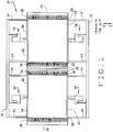
- FIG. 1 illustrates a plan view of a micro-electromechanical system (MEMS) device 10, for example, a gyroscope.
- MEMS device 10 is formed on a substrate (not shown) and includes at least one proof mass 12, a plurality of suspensions 14 for supporting proof masses 12, and at least one cross beam 16 connected to suspensions 14.
- suspensions 14 are individually and directly connected to the substrate.
- MEMS device 10 also includes motor drive combs 18, motor pickoff combs 20, and sense plates 22, which correspond to individual proof masses 12.
- Proof masses 12 are fabricated from any mass suitable for use in a MEMS device.
- proof mass 12 is a plate of silicon. Other materials compatible with micro-machining techniques may also be utilized. While Figure 1 shows two proof masses 12, MEMS devices utilizing fewer or greater than two proof masses may also be utilized.
- Proof masses 12 are located substantially between motor drive comb 18 and motor pickoff comb 20.
- Proof masses 12 include a plurality of comb-like electrodes 26. A portion of electrodes 26 extends towards motor drive comb 18 and a portion of electrodes 26 extends towards motor pickoff comb 20. While, in the illustrated embodiment, proof masses 12 have thirty-four electrodes 26, it is known to utilize proof masses incorporating different numbers of electrodes. In other embodiments of MEM devices (not shown), motor drive comb and motor pickoff comb may be located next to one another.
- Proof masses 12, in the embodiment shown, are supported above a respective sense plate 22 by suspensions 14. While four suspensions 14 are depicted for suspending each proof mass 12, any number of suspensions 14 which properly support proof masses 12 may be utilized.
- Suspensions 14 are, in one embodiment, beams micro-machined from a silicon wafer. Suspensions 14 also act as springs allowing proof masses 12 to move within a drive plane (X-axis) and a sense plane (Y-axis), as shown in Figure 1 .
- Motor drive combs 18 include a plurality of comb-like electrodes 28 extending towards a respective proof mass 12. While motor drive combs 18 are shown as having eighteen electrodes 28, the number of electrodes 28 on motor drive combs 18 typically is determined by the number of electrodes 26 on the respective proof mass 12. Motor drive combs are typically connected to drive electronics (not shown in Figure 1 ). Electrodes 26 and electrodes 28 are interdigitated as they extend from respective proof masses 12 and motor drive combs 18 and form capacitors which are utilized to generate motion in the drive plane (X-axis).
- Motor pickoff combs 20 also include a plurality of comb-like electrodes 30 extending towards a respective proof mass 12. While motor pickoff combs 20 are depicted as having eighteen electrodes 30, the number of electrodes 30 extending from motor pickoff combs 20 is typically determined by the number of electrodes 26 on a respective proof mass 12. Motor pickoff combs 20 are sometimes referred to as sense combs. Electrodes 26 and electrodes 30 are interdigitated as they extend from respective proof masses 12 and motor pickoff combs 20 and form capacitors which are utilized to sense motion in the drive plane (X-axis).
- Sense plates 22 are parallel with their respective proof mass 12 and form a capacitor. If an angular rate (i.e. an aircraft turning) is applied to MEMS device 10 operating as a gyroscope along an input vector (Z-axis) while the at least one proof mass 12 is oscillating along the drive plane (X-axis), a Coriolis acceleration is detected in the sense plane (Y-axis). The capacitance is used to sense motion in the sense plane (Y-axis). An output of MEMS device 10 typically is a signal proportional to the change in capacitance caused by the motion.
- Sense plates 22 are typically connected to sense electronics, not shown in Figure 1 . Sense electronics detect changes in capacitance as proof masses 12 move toward and/or away from their respective sense plates 22 and the respective motor drive combs 18 and motor pickoff combs 20.
- Motor pickoff combs 20 are typically connected to a bias voltage (not shown) used in sensing motion of proof masses 12.
- Motor drive combs 18 are typically connected to drive electronics (not shown).
- the drive electronics cause the respective proof mass 12 to oscillate at substantially a tuning fork frequency along the drive plane (X-axis) by using the capacitors formed by the plurality of interdigitated comb-like electrodes 26, 28 of proof mass 12 and motor drive comb 18.
- MEMS device 10 has two closely spaced modes of oscillation. One of the modes, sometimes referred to as a motor mode, is driven by an electrostatic force, at a resonant frequency of device 10 to produce a relatively large amplitude of oscillation.
- a Coriolis force is produced which is proportional to the velocity of proof mass 12 in the motor mode.
- the Coriolis force drives proof masse 12 in a sense mode direction at a frequency of the motor mode.
- One or more electrodes are provided to detect oscillations in the sense mode, as described below, utilizing capacitance.
- a DC and/or an AC bias voltage is applied to sense electrodes, so that a motion of proof masses 12 in the sense mode produces an output current.
- MEMS devices for example, gyroscopes are subjected to extreme shock and vibration exposure, but also have to be mechanically sensitive enough to measure minute angular velocities and linear accelerations.
- Such forces may cause extensions 26 of proof masses 12 to forcefully come into contact with one or more of motor drive comb 18, its extensions 28, motor pickoff comb 20, and its extensions 30.
- electrostatic forces might cause proof mass 12 to remain in physical contact with the component of device 10 the proof mass 12 has contacted.
- Other forces may cause the main body of proof mass 12 to come into contact with sense plate 22. Again, the electrostatic forces may cause proof mass 12 to remain in contact with sense plate 22.
- MEMS device 10 is also configured with a plurality of deceleration stops 50 which reduce or alleviate the above described operational problems caused by excessive external mechanical forces.
- Device 10 utilizes deceleration stops 50 to provide the external force protection.
- Proof masses 12 are further identified as a left proof mass 54 and a right proof mass 56.
- the terms "left” and “right” as used herein are for illustrative purposes with respect to the Figures only to describe operation of deceleration stops 50, and do not imply any type of structural limitations of MEMS device 10.
- Left proof mass 54 and right proof mass 56 are supported above the substrate, as described above, by suspensions 14.
- suspensions 14 suspend proof masses 54 and 56 above a substrate (not shown) onto which a sense plate (not shown) is typically mounted, suspensions 14 also allow proof masses 54 and 56 to vibrate upon application of a bias voltage. As proof masses 54 and 56 vibrate, extensions 26 move back and forth between extensions 28 of motor drive combs 18 and extensions 30 of motor pickoff combs 20, causing capacitance changes which can be quantified.
- FIG 2 is an illustration which details a deceleration stop 50 which operates to prevent left proof mass 54 from contacting motor drive comb 18 and motor sense comb 20. While a single deceleration stop 50 is illustrated and described with respect to left proof mass 54, it is to be understood that the description applies to deceleration stops utilized in conjunction with any proof mass (including right proof mass 56) and that multiple deceleration stops 50 can be associated with any individual proof mass (as shown in Figure 1 ). Deceleration stop 50 includes a body 60 which, in one embodiment, is located between cross beam 16 and proof mass 54, and is attached to crossbeam 16 through an anchoring extension 62. In one embodiment, body 60 is attached to the substrate and provides an anchoring function for the MEMS device.
- deceleration beams 64 extend from body 60 towards proof mass 54.
- a deceleration extension 66 located in between deceleration beams 64 extends from proof mass 54. Deceleration beams 64 and deceleration extension 66 allow proof mass 54 to move freely under normal motion conditions, but serve to decelerate proof mass 54 when the motion of proof mass 54 exceeds a certain limit.
- deceleration beams 64 are positioned closer to extensions 86 then proof mass 54 is to combs 28 and 30. As shown in Figures 1 and 2 , deceleration beams 64 and deceleration extensions 66, in one embodiment, are elongated rectangular structures.
- deceleration extension 66 when a motion of proof mass 54 causes deceleration extension 66 to engage one of deceleration beams 64, due to an external force, one or both of deceleration beams 64 and deceleration extension 66 bend, decelerating proof mass 54 such that when proof mass 54 contacts a fixed stop, an impact is significantly reduced or eliminated.
- the deceleration of proof mass 54 due to deceleration stops 50 prevents damage to the interdigitating members of proof mass 54, motor drive comb 18, and motor pickoff comb 20.
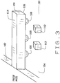
- FIG 3 is an illustration showing one embodiment of a deceleration extension 100 extending from a proof mass 102. It is known that when a proof mass 102 experiences a downward motion that causes proof mass 102 to contact a sense plate 104 electrostatic forces may cause proof mass 102 to remain in contact with sense plate 104 once the forces that originally caused the downward motion of proof mass 102 cease to exist. Continuing contact between proof mass 102 and sense plate 104 causes the MEMS device to cease to function.
- a bottom surface 106 of deceleration extension 100 is formed with a number of raised, semi-spherical areas 108 extending downward from deceleration extension 100.
- substrate 110 is formed with raised areas 112 which engage deceleration extensions 100 directly (as shown) or that engage raised, semi-spherical areas 108 to provide even more separation between proof mass 102 and sense plate 104.
- a top surface 114 of deceleration extension is formed with a number of raised areas (not shown) similar to raised, semi-spherical areas 108 which are configured to reduce or eliminate contact between the proof mass and components of the MEMS device which are above the proof mass. While raised areas 108 are described and shown as being semi-spherical and raised areas 112 are shown as rectangular blocks, it is understood that other embodiments exist which utilize different shapes to provide the same functionality.
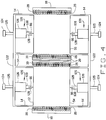
- Figures 4 and 5 illustrate an alternative embodiment of deceleration stops 120.
- Components in Figures 4 and 5 which are the same as components shown in Figures 1 and 2 are shown utilizing the same reference numerals as utilized in Figures 1 and 2 .
- crossbeams 122 are connected to the substrate (not shown) utilizing anchors 124 and anchoring extensions 125 that extend between anchors 124 and crossbeams 122.
- a body 126 extends from crossbeams 122 which includes deceleration beams 128 that extend towards one of respective proof masses 54 and 56.
- Body 126 extends from crossbeam 122 towards a proof mass 54, 56 and can be any shape that can be formed integrally with, and extend from crossbeams 122.
- body 126 is rectangular in shape.
- deceleration stops 120 is shown in more detail in Figure 5 .
- Deceleration beams 128 are configured to engage deceleration extension 66, based upon movements of proof mass 54. Deceleration stops 120 differ from deceleration stops 50 (shown in Figures 1 and 2 ) since deceleration stops 120 do not provide the anchoring function for the suspension of MEMS device as body 60 (shown in Figure 2 ) does.
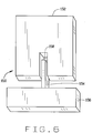
- FIG. 6 is an illustration showing an example of a deceleration stop 150 for decelerating proof masses 152 that is not part of the invention. It should be noted that proof mass 152 is shown in a partial view, with only the portion relevant to deceleration stop 150 being shown.
- a deceleration beam 154 extends from a body 156 anchored to a substrate (not shown) towards proof mass 152.
- proof mass 152 is formed with a rectangular indentation 158 that engages deceleration beam 154.
- Forming proof masses with indentations 158, rather than deceleration extensions, may allow a larger proof mass to be formed for a given area.
- a deceleration beam may extend from a proof mass, while a deceleration extension is formed within the anchoring body.
- a MEMS device can incorporate more than one deceleration beam 154 and indentation 158 as a deceleration stop.
- several deceleration stops 150 using either single or multiple deceleration beams 154 and indentations 158 can be incorporated into a MEMS device, in a configuration similar to that shown in Figure 1 , where four deceleration stops 50 are illustrated.
- proof mass 152 may be constructed with a plurality of raised, semi-spherical areas 108 (shown in Figure 3 ) to alleviate the contacting problems between proof masses and sense plates described with respect to Figure 3 .
- deceleration stop embodiments and the embodiments which are utilized to counteract the effects of up and down movement of proof masses are utilized to protect the components of MEMS devices from extreme forces that can be encountered during use.
- MEMS devices the descriptions should be construed to be include, but not be limited to, MEMS gyroscopes, inertial measurement units, accelerometers, pressure sensors, and temperature sensors.
Landscapes
- Engineering & Computer Science (AREA)
- Physics & Mathematics (AREA)
- General Physics & Mathematics (AREA)
- Computer Hardware Design (AREA)
- Microelectronics & Electronic Packaging (AREA)
- Radar, Positioning & Navigation (AREA)
- Remote Sensing (AREA)
- Gyroscopes (AREA)
- Micromachines (AREA)
- Pressure Sensors (AREA)
- General Electrical Machinery Utilizing Piezoelectricity, Electrostriction Or Magnetostriction (AREA)
Claims (6)
- Vorrichtung mikroelektromechanischer Systeme (Micro-Electro-Mechanical-Systems device, MEMS-Vorrichtung) (10), umfassend:ein Substrat (110), das mindestens einen Anker umfasst;eine Prüfmasse (12, 54, 56, 102), die mindestens eine Abbremserweiterung (66, 100) umfasst, die sich von der Prüfmasse (12, 54, 56, 102) aus erstreckt;einen Motorantriebskamm (18);einen Motorerfassungskamm (20);eine Vielzahl von Aufhängungen (14), die konfiguriert sind, um die Prüfmasse (12, 54, 56, 102) über dem Substrat (110) und zwischen dem Motorantriebskamm (18) und dem Motorerfassungskamm (20) aufzuhängen, wobei die Aufhängungen (14) an dem Substrat (110) verankert sind;einen Körper (60, 126), der an dem Substrat (110) befestigt ist; undmindestens zwei Abbremsträger (64, 128), die sich von dem Körper (60, 126) aus erstrecken, wobei die Abbremsträger (64, 128) konfiguriert sind, um die mindestens eine Abbremserweiterung (66, 100) zu ergreifen und um die Prüfmasse (12, 54, 56, 102) zu stoppen oder zu verlangsamen, bevor die Prüfmasse in einen Kontakt mit dem Motorantriebskamm (18) und dem Motorerfassungskamm (20) tritt; wobei die Abbremserweiterung (66, 100) und Abbremsträger (64, 128) konfiguriert sind, um sich zu verbiegen, wenn sie ergriffen werden und um eine Abbremsfunktion für die Prüfmasse (12, 54, 56, 102) bereitzustellen; unddadurch gekennzeichnet, dassdas Substrat (110) mindestens einen erhöhten Bereich (112) umfasst, der konfiguriert ist, um die Abbremserweiterung (66, 100) zu ergreifen, wobei der erhöhte Bereich (112) konfiguriert ist, um einen Kontakt zwischen der Prüfmasse (12, 54, 56, 102) und den Komponenten der Vorrichtung unter der Prüfmasse zu verringern oder auszuschließen;wobei die mindestens eine Abbremserweiterung (66, 100) umfasst:eine Oberseite (114); undeinen erhöhten Bereich auf der Oberseite, wobei der erhöhte Bereich konfiguriert ist, um einen Kontakt zwischen der Prüfmasse (12, 54, 56, 102) und den Komponenten der Vorrichtung über der Prüfmasse zu verringern oder auszuschließen.
- Vorrichtung (10) nach Anspruch 1, wobei die Vorrichtung außerdem mindestens einen Querträger (16) umfasst, der sich zwischen den Aufhängungen (14) erstreckt, wobei der Körper (60, 126) mit dem Querträger (16) verbunden ist und an dem Substrat (110) befestigt ist.
- Vorrichtung (10) nach Anspruch 2, wobei die Vorrichtung außerdem eine Verankerungserweiterung (62) umfasst, die verwendet wird, um den Körper (60, 126) mit dem Querträger (16) zu verbinden.
- Vorrichtung (10) nach Anspruch 1, wobei die Vorrichtung außerdem umfasst:mindestens einen Querträger (122), der sich zwischen den Aufhängungen (14) erstreckt; undeinen Anker (124), der an dem Querträger und dem Substrat (110) befestigt ist, wobei der Körper (60, 126) mit dem Querträger verbunden ist.
- Vorrichtung (10) nach Anspruch 1, wobei die mindestens eine Abbremserweiterung (66, 100) umfasst:eine Unterseite (106); undmindestens einen erhöhten Bereich (108) auf der Unterseite, wobei die erhöhten Bereiche konfiguriert sind, um einen Kontakt zwischen der Prüfmasse (12, 54, 56, 102) und den Komponenten der Vorrichtung (10) unter der Prüfmasse (12, 54, 56, 102) zu verringern oder auszuschließen.
- Vorrichtung (10) nach Anspruch 1, wobei die mindestens eine Abbremserweiterung (66, 100) und der mindestens eine Abbremsträger (64, 128) lang gestreckte rechteckige Strukturen sind.
Applications Claiming Priority (3)
| Application Number | Priority Date | Filing Date | Title |
|---|---|---|---|
| US10/320,850 US6865944B2 (en) | 2002-12-16 | 2002-12-16 | Methods and systems for decelerating proof mass movements within MEMS structures |
| US320850 | 2002-12-16 | ||
| PCT/US2003/040317 WO2004059250A2 (en) | 2002-12-16 | 2003-12-15 | Methods and systems for decelarating proof mass movements within mems structures |
Publications (2)
| Publication Number | Publication Date |
|---|---|
| EP1573272A2 EP1573272A2 (de) | 2005-09-14 |
| EP1573272B1 true EP1573272B1 (de) | 2018-07-11 |
Family
ID=32506972
Family Applications (1)
| Application Number | Title | Priority Date | Filing Date |
|---|---|---|---|
| EP03814151.1A Expired - Lifetime EP1573272B1 (de) | 2002-12-16 | 2003-12-15 | Mems-vorrichtung mit mitteln zum abbremsen von prüfmassenbewegungen |
Country Status (7)
| Country | Link |
|---|---|
| US (1) | US6865944B2 (de) |
| EP (1) | EP1573272B1 (de) |
| JP (1) | JP5117665B2 (de) |
| KR (1) | KR20050086918A (de) |
| CN (1) | CN100520299C (de) |
| AU (1) | AU2003301040A1 (de) |
| WO (1) | WO2004059250A2 (de) |
Families Citing this family (34)
| Publication number | Priority date | Publication date | Assignee | Title |
|---|---|---|---|---|
| US7194903B2 (en) * | 2004-12-14 | 2007-03-27 | Honeywell International Inc. | Suspension mechanism for high performance accelerometers |
| JP2006214743A (ja) * | 2005-02-01 | 2006-08-17 | Matsushita Electric Works Ltd | 半導体加速度センサ |
| JP4919750B2 (ja) * | 2006-09-27 | 2012-04-18 | 富士通株式会社 | マイクロ構造体製造方法およびマイクロ構造体 |
| US8011247B2 (en) * | 2008-06-26 | 2011-09-06 | Honeywell International Inc. | Multistage proof-mass movement deceleration within MEMS structures |
| US8187902B2 (en) * | 2008-07-09 | 2012-05-29 | The Charles Stark Draper Laboratory, Inc. | High performance sensors and methods for forming the same |
| DE102009001244A1 (de) * | 2009-02-27 | 2010-09-02 | Sensordynamics Ag | Mikro-Gyroskop zur Ermittlung von Rotationsbewegungen um eine x-, y- oder z-Achse |
| CN102483328B (zh) * | 2009-09-09 | 2015-08-05 | 大陆-特韦斯贸易合伙股份公司及两合公司 | 具有线性和旋转地震元件的双轴、抗震旋转速率传感器 |
| US8776601B2 (en) | 2010-11-23 | 2014-07-15 | Honeywell International Inc. | MEMS sensor using multi-layer movable combs |
| US8748206B2 (en) | 2010-11-23 | 2014-06-10 | Honeywell International Inc. | Systems and methods for a four-layer chip-scale MEMS device |
| US9171964B2 (en) | 2010-11-23 | 2015-10-27 | Honeywell International Inc. | Systems and methods for a three-layer chip-scale MEMS device |
| US9493344B2 (en) | 2010-11-23 | 2016-11-15 | Honeywell International Inc. | MEMS vertical comb structure with linear drive/pickoff |
| US9091539B2 (en) | 2011-06-10 | 2015-07-28 | Honeywell International Inc. | Gyroscope dynamic motor amplitude compensation for enhanced rate estimation during startup |
| DE102011085023B4 (de) | 2011-10-21 | 2020-07-09 | Robert Bosch Gmbh | Bauelement und Verfahren zum Betrieb eines Bauelements |
| WO2013188131A1 (en) * | 2012-06-13 | 2013-12-19 | Purdue Research Foundation | Microelectromechanical system and methods of use |
| CN102701137B (zh) * | 2012-06-19 | 2015-06-17 | 中国电子科技集团公司第十三研究所 | 具有三维止档结构的抗过载mems器件及其加工方法 |
| US20140260613A1 (en) * | 2013-03-15 | 2014-09-18 | Invensense, Inc. | Elastic bump stops for mems devices |
| CN103292798A (zh) * | 2013-05-22 | 2013-09-11 | 同济大学 | 一种抗高强度冲击的音叉式微机械陀螺 |
| JP6206651B2 (ja) * | 2013-07-17 | 2017-10-04 | セイコーエプソン株式会社 | 機能素子、電子機器、および移動体 |
| US9476712B2 (en) * | 2013-07-31 | 2016-10-25 | Honeywell International Inc. | MEMS device mechanism enhancement for robust operation through severe shock and acceleration |
| JP2015123526A (ja) * | 2013-12-26 | 2015-07-06 | ソニー株式会社 | 機能素子、加速度センサおよびスイッチ |
| JP6448448B2 (ja) * | 2015-04-10 | 2019-01-09 | 株式会社東芝 | ジャイロセンサの角速度の取得方法及び取得装置 |
| JP6562878B2 (ja) * | 2016-06-30 | 2019-08-21 | 株式会社東芝 | 角速度取得装置 |
| US20180180419A1 (en) * | 2016-10-05 | 2018-06-28 | Freescale Semiconductor, Inc. | Inertial sensor with motion limit structure |
| US10247753B2 (en) | 2017-02-14 | 2019-04-02 | Nxp Usa, Inc. | MEMS device with off-axis shock protection |
| US10753744B2 (en) * | 2017-03-15 | 2020-08-25 | Honeywell International Inc. | MEMS out of plane actuator |
| US10767992B2 (en) * | 2017-03-24 | 2020-09-08 | Kabushiki Kaisha Toshiba | Gyro sensor system |
| CN107607100B (zh) * | 2017-10-19 | 2019-09-27 | 北方电子研究院安徽有限公司 | 一种硅微机械角振动陀螺抗冲击弹性止挡结构 |
| US10502759B2 (en) | 2017-10-24 | 2019-12-10 | Nxp Usa, Inc. | MEMS device with two-stage motion limit structure |
| IT201900024475A1 (it) * | 2019-12-18 | 2021-06-18 | St Microelectronics Srl | Dispositivo micromeccanico con gruppo elastico a costante elastica variabile |
| DE102020203590A1 (de) | 2020-03-20 | 2021-09-23 | Robert Bosch Gesellschaft mit beschränkter Haftung | Mikromechanisches Bauelement, insbesondere Beschleunigungsensor oder Drehratensensor, mit einer Anschlagsanordnung umfassend eine Biegefederanordnung |
| DE102020212998A1 (de) | 2020-10-15 | 2022-04-21 | Robert Bosch Gesellschaft mit beschränkter Haftung | Mikromechanischer z-Inertialsensor |
| IT202200003506A1 (it) | 2022-02-24 | 2023-08-24 | St Microelectronics Srl | Dispositivo micromeccanico per la misura migliorata di accelerazioni |
| US12529562B2 (en) | 2023-07-14 | 2026-01-20 | Nxp Usa, Inc. | Compliant stops for mems inertial device drive PLL stability |
| DE102024206130A1 (de) * | 2024-07-01 | 2026-01-08 | Robert Bosch Gesellschaft mit beschränkter Haftung | Mikromechanisches Bauelement |
Citations (1)
| Publication number | Priority date | Publication date | Assignee | Title |
|---|---|---|---|---|
| US5817942A (en) * | 1996-02-28 | 1998-10-06 | The Charles Stark Draper Laboratory, Inc. | Capacitive in-plane accelerometer |
Family Cites Families (30)
| Publication number | Priority date | Publication date | Assignee | Title |
|---|---|---|---|---|
| JPH0679033B2 (ja) | 1987-12-21 | 1994-10-05 | 日産自動車株式会社 | 半導体加速度センサ |
| US5111693A (en) | 1988-01-13 | 1992-05-12 | The Charles Stark Draper Laboratory, Inc. | Motion restraints for micromechanical devices |
| US4882933A (en) | 1988-06-03 | 1989-11-28 | Novasensor | Accelerometer with integral bidirectional shock protection and controllable viscous damping |
| US5025346A (en) * | 1989-02-17 | 1991-06-18 | Regents Of The University Of California | Laterally driven resonant microstructures |
| US5205171A (en) * | 1991-01-11 | 1993-04-27 | Northrop Corporation | Miniature silicon accelerometer and method |
| US5349855A (en) * | 1992-04-07 | 1994-09-27 | The Charles Stark Draper Laboratory, Inc. | Comb drive micromechanical tuning fork gyro |
| JPH05340955A (ja) * | 1992-06-12 | 1993-12-24 | Murata Mfg Co Ltd | 加速度センサ |
| US5458000A (en) * | 1993-07-20 | 1995-10-17 | Honeywell Inc. | Static pressure compensation of resonant integrated microbeam sensors |
| US5581035A (en) * | 1994-08-29 | 1996-12-03 | The Charles Stark Draper Laboratory, Inc. | Micromechanical sensor with a guard band electrode |
| US5646348A (en) * | 1994-08-29 | 1997-07-08 | The Charles Stark Draper Laboratory, Inc. | Micromechanical sensor with a guard band electrode and fabrication technique therefor |
| DE19526903B4 (de) * | 1995-07-22 | 2005-03-10 | Bosch Gmbh Robert | Drehratensensor |
| DE19539049A1 (de) | 1995-10-20 | 1997-04-24 | Bosch Gmbh Robert | Verfahren zur Herstellung eines Coriolis-Drehratensensors |
| US5892153A (en) * | 1996-11-21 | 1999-04-06 | The Charles Stark Draper Laboratory, Inc. | Guard bands which control out-of-plane sensitivities in tuning fork gyroscopes and other sensors |
| JPH10267658A (ja) * | 1997-03-24 | 1998-10-09 | Nissan Motor Co Ltd | 振動型角速度センサ |
| US5952574A (en) * | 1997-04-29 | 1999-09-14 | The Charles Stark Draper Laboratory, Inc. | Trenches to reduce charging effects and to control out-of-plane sensitivities in tuning fork gyroscopes and other sensors |
| FR2763694B1 (fr) * | 1997-05-23 | 1999-07-30 | Sextant Avionique | Micro-accelerometre a resonateur capacitif |
| US6718605B2 (en) * | 1997-09-08 | 2004-04-13 | The Regents Of The University Of Michigan | Single-side microelectromechanical capacitive accelerometer and method of making same |
| US6040625A (en) * | 1997-09-25 | 2000-03-21 | I/O Sensors, Inc. | Sensor package arrangement |
| IL122947A (en) * | 1998-01-15 | 2001-03-19 | Armament Dev Authority State O | Micro-electro-opto-mechanical inertial sensor with integrative optical sensing |
| US6481285B1 (en) * | 1999-04-21 | 2002-11-19 | Andrei M. Shkel | Micro-machined angle-measuring gyroscope |
| JP2000338124A (ja) * | 1999-05-26 | 2000-12-08 | Matsushita Electric Works Ltd | 半導体加速度センサ |
| US6257059B1 (en) * | 1999-09-24 | 2001-07-10 | The Charles Stark Draper Laboratory, Inc. | Microfabricated tuning fork gyroscope and associated three-axis inertial measurement system to sense out-of-plane rotation |
| US6230566B1 (en) * | 1999-10-01 | 2001-05-15 | The Regents Of The University Of California | Micromachined low frequency rocking accelerometer with capacitive pickoff |
| JP4126826B2 (ja) * | 1999-11-05 | 2008-07-30 | 株式会社デンソー | 角速度センサ |
| EP2136215A3 (de) * | 2000-06-21 | 2014-01-01 | ION Geophysical Corporation | Beschleunigungsmeter mit gebogenen Aufhängungsbalken |
| US20020066317A1 (en) * | 2000-12-06 | 2002-06-06 | Gang Lin | Micro yaw rate sensors |
| SG103276A1 (en) * | 2001-01-03 | 2004-04-29 | Inst Materials Research & Eng | Vibratory in-plane tunnelling gyroscope |
| US6426538B1 (en) * | 2001-01-16 | 2002-07-30 | Honeywell International Inc. | Suspended micromachined structure |
| DE10116931A1 (de) * | 2001-04-05 | 2002-10-17 | Bosch Gmbh Robert | Sensor |
| US6619123B2 (en) * | 2001-06-04 | 2003-09-16 | Wisconsin Alumni Research Foundation | Micromachined shock sensor |
-
2002
- 2002-12-16 US US10/320,850 patent/US6865944B2/en not_active Expired - Lifetime
-
2003
- 2003-12-15 WO PCT/US2003/040317 patent/WO2004059250A2/en not_active Ceased
- 2003-12-15 KR KR1020057011167A patent/KR20050086918A/ko not_active Ceased
- 2003-12-15 CN CNB2003801097659A patent/CN100520299C/zh not_active Expired - Fee Related
- 2003-12-15 AU AU2003301040A patent/AU2003301040A1/en not_active Abandoned
- 2003-12-15 EP EP03814151.1A patent/EP1573272B1/de not_active Expired - Lifetime
- 2003-12-15 JP JP2004563737A patent/JP5117665B2/ja not_active Expired - Fee Related
Patent Citations (1)
| Publication number | Priority date | Publication date | Assignee | Title |
|---|---|---|---|---|
| US5817942A (en) * | 1996-02-28 | 1998-10-06 | The Charles Stark Draper Laboratory, Inc. | Capacitive in-plane accelerometer |
Also Published As
| Publication number | Publication date |
|---|---|
| EP1573272A2 (de) | 2005-09-14 |
| WO2004059250A3 (en) | 2004-08-19 |
| CN1748121A (zh) | 2006-03-15 |
| JP2006510029A (ja) | 2006-03-23 |
| JP5117665B2 (ja) | 2013-01-16 |
| CN100520299C (zh) | 2009-07-29 |
| US6865944B2 (en) | 2005-03-15 |
| AU2003301040A1 (en) | 2004-07-22 |
| WO2004059250A2 (en) | 2004-07-15 |
| US20040112133A1 (en) | 2004-06-17 |
| KR20050086918A (ko) | 2005-08-30 |
Similar Documents
| Publication | Publication Date | Title |
|---|---|---|
| EP1573272B1 (de) | Mems-vorrichtung mit mitteln zum abbremsen von prüfmassenbewegungen | |
| US8011247B2 (en) | Multistage proof-mass movement deceleration within MEMS structures | |
| US6860151B2 (en) | Methods and systems for controlling movement within MEMS structures | |
| EP2616771B1 (de) | Mikroverarbeiteter monolithischer inertialsensor mit sechs achsen | |
| CN101443629B (zh) | 具有联接梁的转速传感器 | |
| JP4214123B2 (ja) | 音叉型振動式memsジャイロスコープ | |
| EP3217147B1 (de) | Mikromechanische detektionsstruktur für mems-sensorvorrichtung, insbesondere einem mems-gyroskop, mit verbesserten ansteuerungsmerkmalen | |
| EP1811661A1 (de) | Frequenzverschiebung von Drehharmonischen bei MEMS-Vorrichtungen | |
| JP2008514968A (ja) | 回転速度センサ | |
| JP2009529666A6 (ja) | 連結棒を有する回転速度センサ | |
| JP2006517301A (ja) | 多周波memsデバイスを同時加工するための方法及びシステム | |
| US7134337B2 (en) | Micromechanical rotational rate sensor | |
| JP2008134243A (ja) | デュアルモードmemsセンサ | |
| US6817244B2 (en) | Methods and systems for actively controlling movement within MEMS structures | |
| EP1389299A1 (de) | Kompensierter und abgestimmter siliziumbasierter mehrfach-beschleunigungs- und drehratensensor | |
| KR20080113048A (ko) | 정밀 기계식 회전 속도 센서 | |
| US6718825B1 (en) | Methods and systems for reducing stick-down within MEMS structures | |
| JP3873266B2 (ja) | 三次元角速度センサ | |
| JP2006029992A (ja) | 振動型圧電加速度センサ |
Legal Events
| Date | Code | Title | Description |
|---|---|---|---|
| PUAI | Public reference made under article 153(3) epc to a published international application that has entered the european phase |
Free format text: ORIGINAL CODE: 0009012 |
|
| 17P | Request for examination filed |
Effective date: 20050623 |
|
| AK | Designated contracting states |
Kind code of ref document: A2 Designated state(s): AT BE BG CH CY CZ DE DK EE ES FI FR GB GR HU IE IT LI LU MC NL PT RO SE SI SK TR |
|
| AX | Request for extension of the european patent |
Extension state: AL LT LV MK |
|
| DAX | Request for extension of the european patent (deleted) | ||
| RBV | Designated contracting states (corrected) |
Designated state(s): DE FR GB IT |
|
| 17Q | First examination report despatched |
Effective date: 20090331 |
|
| RAP1 | Party data changed (applicant data changed or rights of an application transferred) |
Owner name: HONEYWELL INTERNATIONAL INC. |
|
| REG | Reference to a national code |
Ref country code: DE Ref legal event code: R079 Ref document number: 60351320 Country of ref document: DE Free format text: PREVIOUS MAIN CLASS: G01C0019560000 Ipc: B81B0003000000 |
|
| GRAP | Despatch of communication of intention to grant a patent |
Free format text: ORIGINAL CODE: EPIDOSNIGR1 |
|
| RIC1 | Information provided on ipc code assigned before grant |
Ipc: G01C 19/5719 20120101ALI20180206BHEP Ipc: B81B 3/00 20060101AFI20180206BHEP |
|
| INTG | Intention to grant announced |
Effective date: 20180227 |
|
| GRAS | Grant fee paid |
Free format text: ORIGINAL CODE: EPIDOSNIGR3 |
|
| GRAA | (expected) grant |
Free format text: ORIGINAL CODE: 0009210 |
|
| AK | Designated contracting states |
Kind code of ref document: B1 Designated state(s): DE FR GB IT |
|
| REG | Reference to a national code |
Ref country code: GB Ref legal event code: FG4D |
|
| REG | Reference to a national code |
Ref country code: DE Ref legal event code: R096 Ref document number: 60351320 Country of ref document: DE |
|
| RIC2 | Information provided on ipc code assigned after grant |
Ipc: G01C 19/5719 20120101ALI20180206BHEP Ipc: B81B 3/00 20060101AFI20180206BHEP |
|
| REG | Reference to a national code |
Ref country code: DE Ref legal event code: R097 Ref document number: 60351320 Country of ref document: DE |
|
| PG25 | Lapsed in a contracting state [announced via postgrant information from national office to epo] |
Ref country code: IT Free format text: LAPSE BECAUSE OF FAILURE TO SUBMIT A TRANSLATION OF THE DESCRIPTION OR TO PAY THE FEE WITHIN THE PRESCRIBED TIME-LIMIT Effective date: 20180711 |
|
| PLBE | No opposition filed within time limit |
Free format text: ORIGINAL CODE: 0009261 |
|
| STAA | Information on the status of an ep patent application or granted ep patent |
Free format text: STATUS: NO OPPOSITION FILED WITHIN TIME LIMIT |
|
| 26N | No opposition filed |
Effective date: 20190412 |
|
| REG | Reference to a national code |
Ref country code: DE Ref legal event code: R119 Ref document number: 60351320 Country of ref document: DE |
|
| PG25 | Lapsed in a contracting state [announced via postgrant information from national office to epo] |
Ref country code: DE Free format text: LAPSE BECAUSE OF NON-PAYMENT OF DUE FEES Effective date: 20190702 |
|
| PGFP | Annual fee paid to national office [announced via postgrant information from national office to epo] |
Ref country code: GB Payment date: 20221220 Year of fee payment: 20 Ref country code: FR Payment date: 20221222 Year of fee payment: 20 |
|
| P01 | Opt-out of the competence of the unified patent court (upc) registered |
Effective date: 20230525 |
|
| REG | Reference to a national code |
Ref country code: GB Ref legal event code: PE20 Expiry date: 20231214 |
|
| PG25 | Lapsed in a contracting state [announced via postgrant information from national office to epo] |
Ref country code: GB Free format text: LAPSE BECAUSE OF EXPIRATION OF PROTECTION Effective date: 20231214 |
|
| PG25 | Lapsed in a contracting state [announced via postgrant information from national office to epo] |
Ref country code: GB Free format text: LAPSE BECAUSE OF EXPIRATION OF PROTECTION Effective date: 20231214 |