EP1573077B1 - Dispositif de brassage rotatif destine au traitement du metal en fusion - Google Patents
Dispositif de brassage rotatif destine au traitement du metal en fusion Download PDFInfo
- Publication number
- EP1573077B1 EP1573077B1 EP03786125A EP03786125A EP1573077B1 EP 1573077 B1 EP1573077 B1 EP 1573077B1 EP 03786125 A EP03786125 A EP 03786125A EP 03786125 A EP03786125 A EP 03786125A EP 1573077 B1 EP1573077 B1 EP 1573077B1
- Authority
- EP
- European Patent Office
- Prior art keywords
- rotor
- gas
- roof
- base
- shaft
- Prior art date
- Legal status (The legal status is an assumption and is not a legal conclusion. Google has not performed a legal analysis and makes no representation as to the accuracy of the status listed.)
- Expired - Lifetime
Links
- 229910052751 metal Inorganic materials 0.000 title claims abstract description 56
- 239000002184 metal Substances 0.000 title claims abstract description 56
- 238000003756 stirring Methods 0.000 title 1
- 239000007789 gas Substances 0.000 claims description 54
- 229910045601 alloy Inorganic materials 0.000 claims description 18
- 239000000956 alloy Substances 0.000 claims description 18
- IJGRMHOSHXDMSA-UHFFFAOYSA-N Atomic nitrogen Chemical compound N#N IJGRMHOSHXDMSA-UHFFFAOYSA-N 0.000 claims description 16
- 238000000034 method Methods 0.000 claims description 14
- 229910052782 aluminium Inorganic materials 0.000 claims description 8
- 229910052757 nitrogen Inorganic materials 0.000 claims description 8
- 238000004140 cleaning Methods 0.000 claims description 7
- XKRFYHLGVUSROY-UHFFFAOYSA-N Argon Chemical compound [Ar] XKRFYHLGVUSROY-UHFFFAOYSA-N 0.000 claims description 6
- 239000004411 aluminium Substances 0.000 claims description 6
- XAGFODPZIPBFFR-UHFFFAOYSA-N aluminium Chemical compound [Al] XAGFODPZIPBFFR-UHFFFAOYSA-N 0.000 claims description 6
- 239000007787 solid Substances 0.000 claims description 6
- 239000000126 substance Substances 0.000 claims description 6
- 230000004048 modification Effects 0.000 claims description 5
- 238000012986 modification Methods 0.000 claims description 5
- 239000006185 dispersion Substances 0.000 claims description 4
- OKTJSMMVPCPJKN-UHFFFAOYSA-N Carbon Chemical compound [C] OKTJSMMVPCPJKN-UHFFFAOYSA-N 0.000 claims description 3
- ZAMOUSCENKQFHK-UHFFFAOYSA-N Chlorine atom Chemical compound [Cl] ZAMOUSCENKQFHK-UHFFFAOYSA-N 0.000 claims description 3
- 229910052786 argon Inorganic materials 0.000 claims description 3
- 239000000460 chlorine Substances 0.000 claims description 3
- 229910052801 chlorine Inorganic materials 0.000 claims description 3
- 229910002804 graphite Inorganic materials 0.000 claims description 3
- 239000010439 graphite Substances 0.000 claims description 3
- 239000000463 material Substances 0.000 claims description 3
- 238000002156 mixing Methods 0.000 claims description 3
- 238000007670 refining Methods 0.000 claims description 3
- RYGMFSIKBFXOCR-UHFFFAOYSA-N Copper Chemical compound [Cu] RYGMFSIKBFXOCR-UHFFFAOYSA-N 0.000 claims description 2
- FYYHWMGAXLPEAU-UHFFFAOYSA-N Magnesium Chemical compound [Mg] FYYHWMGAXLPEAU-UHFFFAOYSA-N 0.000 claims description 2
- 150000001638 boron Chemical class 0.000 claims description 2
- 150000008280 chlorinated hydrocarbons Chemical class 0.000 claims description 2
- 239000010949 copper Substances 0.000 claims description 2
- 229910052802 copper Inorganic materials 0.000 claims description 2
- 229910052749 magnesium Inorganic materials 0.000 claims description 2
- 239000011777 magnesium Substances 0.000 claims description 2
- 159000000000 sodium salts Chemical class 0.000 claims description 2
- 229910052712 strontium Inorganic materials 0.000 claims description 2
- CIOAGBVUUVVLOB-UHFFFAOYSA-N strontium atom Chemical compound [Sr] CIOAGBVUUVVLOB-UHFFFAOYSA-N 0.000 claims description 2
- 150000003608 titanium Chemical class 0.000 claims 1
- 230000000052 comparative effect Effects 0.000 description 23
- 238000007872 degassing Methods 0.000 description 23
- UFHFLCQGNIYNRP-UHFFFAOYSA-N Hydrogen Chemical compound [H][H] UFHFLCQGNIYNRP-UHFFFAOYSA-N 0.000 description 10
- 230000003749 cleanliness Effects 0.000 description 7
- 239000000155 melt Substances 0.000 description 7
- 238000012360 testing method Methods 0.000 description 7
- 230000004907 flux Effects 0.000 description 5
- 239000001257 hydrogen Substances 0.000 description 5
- 229910052739 hydrogen Inorganic materials 0.000 description 5
- 230000002093 peripheral effect Effects 0.000 description 4
- 230000008569 process Effects 0.000 description 4
- 229910052710 silicon Inorganic materials 0.000 description 4
- 238000005266 casting Methods 0.000 description 3
- 230000007547 defect Effects 0.000 description 3
- 239000011261 inert gas Substances 0.000 description 3
- 238000002347 injection Methods 0.000 description 3
- 239000007924 injection Substances 0.000 description 3
- 239000000203 mixture Substances 0.000 description 3
- 230000009467 reduction Effects 0.000 description 3
- 229910003407 AlSi10Mg Inorganic materials 0.000 description 2
- 229910000676 Si alloy Inorganic materials 0.000 description 2
- 230000009286 beneficial effect Effects 0.000 description 2
- 230000006872 improvement Effects 0.000 description 2
- 239000012535 impurity Substances 0.000 description 2
- 230000007306 turnover Effects 0.000 description 2
- 229910000838 Al alloy Inorganic materials 0.000 description 1
- 229910000789 Aluminium-silicon alloy Inorganic materials 0.000 description 1
- QYEXBYZXHDUPRC-UHFFFAOYSA-N B#[Ti]#B Chemical compound B#[Ti]#B QYEXBYZXHDUPRC-UHFFFAOYSA-N 0.000 description 1
- 241001124569 Lycaenidae Species 0.000 description 1
- 229910000861 Mg alloy Inorganic materials 0.000 description 1
- 241001275902 Parabramis pekinensis Species 0.000 description 1
- OAICVXFJPJFONN-UHFFFAOYSA-N Phosphorus Chemical compound [P] OAICVXFJPJFONN-UHFFFAOYSA-N 0.000 description 1
- 229910033181 TiB2 Inorganic materials 0.000 description 1
- ATJFFYVFTNAWJD-UHFFFAOYSA-N Tin Chemical compound [Sn] ATJFFYVFTNAWJD-UHFFFAOYSA-N 0.000 description 1
- RTAQQCXQSZGOHL-UHFFFAOYSA-N Titanium Chemical compound [Ti] RTAQQCXQSZGOHL-UHFFFAOYSA-N 0.000 description 1
- GANNOFFDYMSBSZ-UHFFFAOYSA-N [AlH3].[Mg] Chemical compound [AlH3].[Mg] GANNOFFDYMSBSZ-UHFFFAOYSA-N 0.000 description 1
- 230000004913 activation Effects 0.000 description 1
- PNEYBMLMFCGWSK-UHFFFAOYSA-N aluminium oxide Inorganic materials [O-2].[O-2].[O-2].[Al+3].[Al+3] PNEYBMLMFCGWSK-UHFFFAOYSA-N 0.000 description 1
- 238000010923 batch production Methods 0.000 description 1
- 230000015572 biosynthetic process Effects 0.000 description 1
- RNFNDJAIBTYOQL-UHFFFAOYSA-N chloral hydrate Chemical compound OC(O)C(Cl)(Cl)Cl RNFNDJAIBTYOQL-UHFFFAOYSA-N 0.000 description 1
- 238000010276 construction Methods 0.000 description 1
- 235000014987 copper Nutrition 0.000 description 1
- 229910052593 corundum Inorganic materials 0.000 description 1
- 230000007423 decrease Effects 0.000 description 1
- 230000002939 deleterious effect Effects 0.000 description 1
- 230000001627 detrimental effect Effects 0.000 description 1
- 230000000694 effects Effects 0.000 description 1
- 239000006023 eutectic alloy Substances 0.000 description 1
- 238000001914 filtration Methods 0.000 description 1
- 239000010419 fine particle Substances 0.000 description 1
- 238000011010 flushing procedure Methods 0.000 description 1
- 238000011835 investigation Methods 0.000 description 1
- 238000011068 loading method Methods 0.000 description 1
- 238000004519 manufacturing process Methods 0.000 description 1
- 230000013011 mating Effects 0.000 description 1
- 238000005259 measurement Methods 0.000 description 1
- 150000001247 metal acetylides Chemical class 0.000 description 1
- 150000002739 metals Chemical class 0.000 description 1
- 238000003801 milling Methods 0.000 description 1
- 238000001556 precipitation Methods 0.000 description 1
- 238000011085 pressure filtration Methods 0.000 description 1
- 238000010926 purge Methods 0.000 description 1
- 238000011002 quantification Methods 0.000 description 1
- 230000000717 retained effect Effects 0.000 description 1
- 238000005070 sampling Methods 0.000 description 1
- 238000010008 shearing Methods 0.000 description 1
- 241000894007 species Species 0.000 description 1
- 239000010936 titanium Substances 0.000 description 1
- 229910052719 titanium Inorganic materials 0.000 description 1
- 229910001845 yogo sapphire Inorganic materials 0.000 description 1
Images


Classifications
-
- F—MECHANICAL ENGINEERING; LIGHTING; HEATING; WEAPONS; BLASTING
- F27—FURNACES; KILNS; OVENS; RETORTS
- F27D—DETAILS OR ACCESSORIES OF FURNACES, KILNS, OVENS, OR RETORTS, IN SO FAR AS THEY ARE OF KINDS OCCURRING IN MORE THAN ONE KIND OF FURNACE
- F27D27/00—Stirring devices for molten material
-
- B—PERFORMING OPERATIONS; TRANSPORTING
- B01—PHYSICAL OR CHEMICAL PROCESSES OR APPARATUS IN GENERAL
- B01F—MIXING, e.g. DISSOLVING, EMULSIFYING OR DISPERSING
- B01F23/00—Mixing according to the phases to be mixed, e.g. dispersing or emulsifying
- B01F23/20—Mixing gases with liquids
- B01F23/23—Mixing gases with liquids by introducing gases into liquid media, e.g. for producing aerated liquids
- B01F23/233—Mixing gases with liquids by introducing gases into liquid media, e.g. for producing aerated liquids using driven stirrers with completely immersed stirring elements
- B01F23/2331—Mixing gases with liquids by introducing gases into liquid media, e.g. for producing aerated liquids using driven stirrers with completely immersed stirring elements characterised by the introduction of the gas along the axis of the stirrer or along the stirrer elements
- B01F23/23311—Mixing gases with liquids by introducing gases into liquid media, e.g. for producing aerated liquids using driven stirrers with completely immersed stirring elements characterised by the introduction of the gas along the axis of the stirrer or along the stirrer elements through a hollow stirrer axis
-
- B—PERFORMING OPERATIONS; TRANSPORTING
- B01—PHYSICAL OR CHEMICAL PROCESSES OR APPARATUS IN GENERAL
- B01F—MIXING, e.g. DISSOLVING, EMULSIFYING OR DISPERSING
- B01F23/00—Mixing according to the phases to be mixed, e.g. dispersing or emulsifying
- B01F23/20—Mixing gases with liquids
- B01F23/23—Mixing gases with liquids by introducing gases into liquid media, e.g. for producing aerated liquids
- B01F23/233—Mixing gases with liquids by introducing gases into liquid media, e.g. for producing aerated liquids using driven stirrers with completely immersed stirring elements
- B01F23/2336—Mixing gases with liquids by introducing gases into liquid media, e.g. for producing aerated liquids using driven stirrers with completely immersed stirring elements characterised by the location of the place of introduction of the gas relative to the stirrer
- B01F23/23364—Mixing gases with liquids by introducing gases into liquid media, e.g. for producing aerated liquids using driven stirrers with completely immersed stirring elements characterised by the location of the place of introduction of the gas relative to the stirrer the gas being introduced between the stirrer elements
- B01F23/233641—Mixing gases with liquids by introducing gases into liquid media, e.g. for producing aerated liquids using driven stirrers with completely immersed stirring elements characterised by the location of the place of introduction of the gas relative to the stirrer the gas being introduced between the stirrer elements at the stirrer axis
-
- B—PERFORMING OPERATIONS; TRANSPORTING
- B01—PHYSICAL OR CHEMICAL PROCESSES OR APPARATUS IN GENERAL
- B01F—MIXING, e.g. DISSOLVING, EMULSIFYING OR DISPERSING
- B01F27/00—Mixers with rotary stirring devices in fixed receptacles; Kneaders
- B01F27/05—Stirrers
- B01F27/11—Stirrers characterised by the configuration of the stirrers
- B01F27/111—Centrifugal stirrers, i.e. stirrers with radial outlets; Stirrers of the turbine type, e.g. with means to guide the flow
- B01F27/1111—Centrifugal stirrers, i.e. stirrers with radial outlets; Stirrers of the turbine type, e.g. with means to guide the flow with a flat disc or with a disc-like element equipped with blades, e.g. Rushton turbine
-
- C—CHEMISTRY; METALLURGY
- C22—METALLURGY; FERROUS OR NON-FERROUS ALLOYS; TREATMENT OF ALLOYS OR NON-FERROUS METALS
- C22B—PRODUCTION AND REFINING OF METALS; PRETREATMENT OF RAW MATERIALS
- C22B21/00—Obtaining aluminium
- C22B21/06—Obtaining aluminium refining
- C22B21/064—Obtaining aluminium refining using inert or reactive gases
-
- C—CHEMISTRY; METALLURGY
- C22—METALLURGY; FERROUS OR NON-FERROUS ALLOYS; TREATMENT OF ALLOYS OR NON-FERROUS METALS
- C22B—PRODUCTION AND REFINING OF METALS; PRETREATMENT OF RAW MATERIALS
- C22B9/00—General processes of refining or remelting of metals; Apparatus for electroslag or arc remelting of metals
- C22B9/05—Refining by treating with gases, e.g. gas flushing also refining by means of a material generating gas in situ
-
- F—MECHANICAL ENGINEERING; LIGHTING; HEATING; WEAPONS; BLASTING
- F27—FURNACES; KILNS; OVENS; RETORTS
- F27D—DETAILS OR ACCESSORIES OF FURNACES, KILNS, OVENS, OR RETORTS, IN SO FAR AS THEY ARE OF KINDS OCCURRING IN MORE THAN ONE KIND OF FURNACE
- F27D3/00—Charging; Discharging; Manipulation of charge
- F27D3/16—Introducing a fluid jet or current into the charge
-
- B—PERFORMING OPERATIONS; TRANSPORTING
- B01—PHYSICAL OR CHEMICAL PROCESSES OR APPARATUS IN GENERAL
- B01F—MIXING, e.g. DISSOLVING, EMULSIFYING OR DISPERSING
- B01F27/00—Mixers with rotary stirring devices in fixed receptacles; Kneaders
- B01F27/05—Stirrers
- B01F27/07—Stirrers characterised by their mounting on the shaft
- B01F27/072—Stirrers characterised by their mounting on the shaft characterised by the disposition of the stirrers with respect to the rotating axis
- B01F27/0725—Stirrers characterised by their mounting on the shaft characterised by the disposition of the stirrers with respect to the rotating axis on the free end of the rotating axis
-
- F—MECHANICAL ENGINEERING; LIGHTING; HEATING; WEAPONS; BLASTING
- F27—FURNACES; KILNS; OVENS; RETORTS
- F27D—DETAILS OR ACCESSORIES OF FURNACES, KILNS, OVENS, OR RETORTS, IN SO FAR AS THEY ARE OF KINDS OCCURRING IN MORE THAN ONE KIND OF FURNACE
- F27D3/00—Charging; Discharging; Manipulation of charge
- F27D3/16—Introducing a fluid jet or current into the charge
- F27D2003/166—Introducing a fluid jet or current into the charge the fluid being a treatment gas
Definitions
- the present invention relates to a rotary device for treating a molten metal.
- defects are introduced in castings and wrought products manufactured from aluminium or its alloys due to porosity arising from the presence of hydrogen gas.
- hydrogen gas diffusing to voids and discontinuities e.g. oxide inclusions
- Other defects such as porosity in castings may also be associated with the presence of hydrogen gas.
- degassing It is common practice to treat molten aluminium and its alloys to remove hydrogen and solid impurities by flushing with a gas such as chlorine, argon, nitrogen or a mixture of these gases, the process commonly being referred to as "degassing" .
- a gas such as chlorine, argon, nitrogen or a mixture of these gases
- One way of performing the degassing is to use a hollow shaft to which a rotor is attached. In use the shaft and rotor are rotated and gas is passed down the shaft and dispersed into the molten metal via the rotor.
- An example of such an assembly is described in EP 0332292 (the entirety of which disclosure is included herein by reference) and shown in Figure 1a.
- the rotor 2 comprises a number of compartments .
- the rotor is characterised by having an open chamber M in its base and by having the outlets larger than the inlets.
- the rotor is connected to a hollow shaft via a tubular connection piece.
- FIG. 1b A further prior art rotor is shown in Figure 1b.
- a number of parallel semi-circular channels or grooves are provided in the peripheral cylindrical surface of the rotor.
- the channels pass diagonally downwardly from the top of the rotor to its base.
- gas passes through a bore passing vertically through the centre of the rotor, exiting the base of the rotor before being dispersed by the rotating rotor as the gas rises.
- EP0183402 discloses a rotary device for dispersing a gas in molten metal which comprises a hollow shaft and a rotor fixedly attached to the shaft.
- the rotor is hollow and divided into a plurality of compartments by a plurality of vanes extending from the shaft.
- the rotor has at least one aperture in its peripheral surface and at least one aperture in its top or bottom.
- molten metal enters the compartments through the aperture in the top or bottom and flows outwardly through the peripheral aperture.
- a duct is provided from the hollow interior of the shaft to each of the compartments to allow the passage of gas from the shaft into the compartments. The gas and molten metal are mixed together within the rotor with the gas being dispersed through the body of the molten metal when emerging from the rotor.
- WO 02/22900 discloses a rotary device which includes a hollow shaft having a rotor with an axial opening fixed to the discharge end of the shaft.
- the rotor is in the form of an annular plate with a plurality of radially mounted upwardly directed blades projecting from the top face of the annular plate and a plurality of radially mounted downwardly directed blades projecting from the bottom face of the annular plate.
- a second annular plate is mounted directly beneath the lower blades, creating segment shaped passageways between the plates and between adjacent radially mounted shearing blades.
- a rotary device for dispersing a gas in a molten metal comprising a hollow shaft at one end of which is a rotor, said rotor having a roof and a base, said roof and base being spaced apart and connected by a plurality of dividers, a passage being defined between each adjacent pair of dividers and the roof and the base, each passage having an inlet and a first outlet, wherein each first outlet is disposed radially outwardly of the respective inlet and arranged to disperse gas laterally of the rotor in use, characterised in that each passage also has a second outlet, each second outlet being disposed in the roof of the rotor and arranged to disperse gas upwardly from the rotor in use, a flow path being defined through the shaft into the inlets of the passages and out of the first and second outlets further characterised in that the rotor is provided with a chamber in which mixing of molten metal and gas can take place, said chamber being located radi
- the inventors have found that the combination of laterally directed and upwardly directed outlets allows smaller and more numerous bubbles of gas to be created which results in significantly more efficient degassing and cleaning compared to the device of EP 0332292 such that the rotation speed can be reduced while maintaining the same efficiency of degassing/cleaning, thereby extending the life of the shaft and rotor, or degassing/cleaning can be achieved more efficiently at the same rotor speed, providing the opportunity to reduce treatment time.
- the rotor is formed from a solid block of material, the roof and the base being constituted by upper and lower regions of the block respectively, an intermediate region of the block having bores therein which define the passages, each divider being defined by the intermediate region between each bore.
- each bore may be of uniform diameter or tapered (inwardly or outwardly). Preferably said bores are of uniform diameter.
- the dividers are in the form of vanes and each passage is a compartment defined between adjacent vanes.
- each second outlet is a cut-out extending inwardly from the outer periphery of the roof.
- the cut-outs are part-circular or semi-circular and are preferably arranged symmetrically around the rotor. It will of course be appreciated that the cut-outs can be of any shape and that one or more of the second outlets could alternatively be constituted by a bore (of any shape) through the roof into one of the compartments.
- the second outlets do not extend downwardly as far as the base of the rotor.
- the rotor has four passages or compartments (defined by four dividers or vanes) with eight second outlets in the form of semi-circular cut-outs arranged symmetrically around the rotor (i.e. two per compartment).
- the number of outlets may be increased (e.g. to 12 or 16) for larger rotors and reduced for smaller rotors.
- the first outlets have a greater cross-sectional area than the inlets.
- the rotor is circular in transverse cross section and is most preferably attached to the shaft at its centre, so as to reduce drag during rotation.
- the shaft and rotor are formed separately, the two being attached together by releasable fixing means.
- the shaft may be connected directly to the rotor (e.g. by providing mating screw threads on each of the shaft and rotor), or indirectly, e.g. via a threaded tubular connection piece.
- the rotor is conveniently formed from a solid block of material (preferably graphite), the compartments being conveniently formed by a milling operation.
- the present invention further resides in a method of treating molten metal comprising the steps of:-
- molten metal is not restricted.
- preferred metals for the treatment include aluminium and all its alloys (including low silicon alloys (4-6% Si) e.g. BS alloy LM4 (AI-Si5Cu3); medium silicon alloys (7.5-9.5% Si) e.g. BS alloy LM25 (Al-Si7Mg); eutectic alloys (10-13% Si) e.g. BS alloy LM6 (Al-Sil2); hypereutectic alloys (> 16% Si) e.g. BS alloy LM30 (Al-Si17Cu4Mg); aluminium magnesium alloys e.g.
- BS alloy LM5 Al-Mg5Sil; Al-Mg6
- magnesium and its alloys e.g. BS alloy AZ91 (8.0-9.5% Al) and BS alloy AZ81 (7.5-9.0% Al)
- copper and its alloys including high conductivity coppers, brasses, tin bronzes, phosphor bronzes, lead bronzes, gunmetals, aluminium bronzes and copper-nickels.
- the gas is an inert gas (such as argon or nitrogen) and is more preferably dry.
- Gases not traditionally regarded as being inert but having no deleterious effect on the metal may also be used such as chlorine, or a chlorinated hydrocarbon.
- the gas may be a mixture of two or more of the foregoing gases. From a balance between cost and inertness of the gas, dry nitrogen is preferred. The method is particularly useful for the removal of hydrogen gas from molten aluminium.
- a preferred rotation speed is 550 rpm or less and more preferably 400 rpm or less, most preferably about 350 rpm. It will also be understood that for any given rotor, the size and geometry of the holding vessel containing the molten metal will influence the optimum or preferred rotor speed.
- the treatment may also be combined with the injection of fluxes into the melt along with the inert purge gas.
- the treatment is then a combined degassing/grain refinement and/or modification and/or cleaning/drossing treatment, in which case the optional treatment substance may be granulated cleaning/drossing, grain refining, modification species or a combination of these (usually referred to as "flux" or "fluxes").
- fluxes may be titanium and/or boron salts (e.g. AlTiB alloy) for grain refining, and sodium salts or strontium (usually as 5-10% master alloy) for modification of aluminium-silicon alloys.
- Such processes are per se well known to the skilled foundryman.
- the required size of the rotor, speed of rotation, gas flow rate and (optional) flux quantity will all be determined by the particular treatment being undertaken, taking into account the mass of metal being treated, the size and geometry of the holding vessel for the molten metal, the optimum treatment time and whether the process is a continuous or a batch process.
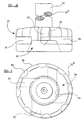
- the device comprises a shaft 20 having a bore 20a therethrough, a rotor 22 and a tubular connection piece 23.
- the rotor 22 is made from graphite and is of unitary construction.
- the rotor 22 is generally disc-shaped and comprises an annular upper part (roof 24) and spaced therefrom an annular lower part (base 26).
- a threaded throughbore 28 is provided centrally in the roof 24 of the rotor 22 and serves in use as an attachment point for the tubular connection piece 23 which is correspondingly externally screw-threaded.
- An open chamber 30 is provided centrally in the base 26 of the rotor 22. The chamber 30 extends upwardly to the roof 24 of the rotor 22 and is continuous with the throughbore 28 in the roof 24, the throughbore 28 and chamber 30 thereby defining a continuous passage vertically through the rotor 22.
- the chamber 30 extends radially outwardly further than the throughbore 28.
- the roof 24 and base 26 are connected by four vanes 32 which are disposed between the roof 24 and the base 26 and which extend outwardly from the periphery of the chamber 30 to the periphery 22a of the rotor 22.
- a compartment 34 is defined between each pair of adjacent vanes 32, the chamber 30 and the roof 24 and the base 26.
- Each compartment 34 has an inlet aperture 36 from the chamber 30 and a first outlet on the periphery 22a of the rotor 22 in the form of an elongated slot 38.
- the outlet slot 38 has a greater cross-sectional area than the inlet aperture 36.
- peripheral edge 22a of the roof 24 of the rotor 22 is provided with a plurality (eight in this embodiment) of part-circular cut-outs 40.
- Each cut-out 40 serves as a second outlet for its respective compartment 34 (in this case two cut-outs 40 are provided per compartment 34).
- An appropriately internally screw-threaded region is provided at one end of the shaft 20 for securely mounting the shaft 20 onto the connection piece 23.
- the opposite end of the shaft 20 is connected to the lower end of a hollow drive shaft (not shown) whose upper end is connected to drive means (in this case an electric motor, not shown) and the bore 20a of the shaft 20 is connected through the hollow drive shaft to a source of gas (not shown).
- the rotor and shaft assembly is immersed in the molten metal to be degassed (in for example a refractory lined ladle or other vessel) and rotated at the desired speed by activation of the electric motor.
- the source of gas is opened and adjusted to the desired flow rate and degassing carried out for a predetermined duration.
- gas passes down the shaft 20 into the rotor chamber 30, where it is mixed with molten metal which is drawn upwardly into the chamber 30.
- the gas/metal dispersion flows into the compartments 34 via the inlets 36 and exits the rotor 22 laterally through the first outlets 38 and upwardly through the second outlets 40.
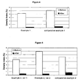
- a rotor as described above having a diameter of 190 mm was used to degas 200 Kg of AlSi10Mg alloy held at 720 °C.
- the gas used was dry nitrogen at a flow rate of 15 L/min.
- the speed of rotation was 450 rpm and degassing was carried out over 5 minutes (Example 1).
- Example 2 Example 2; treatment time 5 minutes, 2 runs, Example 3; treatment time 3 minutes, 2 runs).
- degassing was carried out under identical conditions to the corresponding Example using a rotor identical to that of Example 1, except that the roof of the rotor was not provided with any cut-outs.
- Table 1 DI (%) (degassing at 450 rpm, 15 L/min for 5 mins)
- Table 2 DI (%) (degassing at 350 rpm, 15 L/min for 5 mins)
- Example 2 Comparative Example 2 run 1 run 2 Before 4.58 6.92 5.34 After 0.38 0.38 0.76
- Table 3 DI (%) (degassing at 350 rpm, 15 L/min for 3 mins)
- a 250kg melt of LM25 was made in a gas-fired bale out furnace.
- the charge comprised a mixture of new ingot and process scrap.
- Each rotor under investigation was mounted in turn on a machine capable of controlling the lance rotation speed and inert gas injection pressure.
- the rotation speed was set at 350rpm for Example 4 and Comparative Example 4, and 550rpm for Comparative Example 5 (manufacturer's recommended rotation speed). Nitrogen was used for the inert gas and the injection pressure was maintained constant throughout the trial.
- the degassing operation was carried out in 5 minute increments for a total time of 15 minutes for each run.
- a MK 3VT Vacuum Density Unit (MK GmbH) was used to provide a density index value at the start of the run and at the end of each 5. minute interval.
- An Alscan [TM] hydrogen analyser was also used on selected runs to provide a direct measure of hydrogen content. Metal cleanliness was measured at the start and end of each 15 minute period using Prefil.
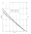
- the Prefil ( Pre ssure Fil tration) test gives an on-line quantitative measurement of oxide films and other inclusions.
- the flow-rate of molten metal through a micro filter at constant temperature and pressure is monitored and used to plot a graph of weight filtered vs time.
- Inclusions in the metal, such as oxide films quickly build-up on the filter surface during a test, reducing the flow-rate through the filter. Therefore the slope and overall shape of the weight filtered vs time curve indicates the level of inclusions present in the metal.
- Oxide films affect the initial slope of the curve (20-30 seconds). They result in straight lines, with a slope that decreases as the number of oxide films increases.
- Fine particulate inclusions such as TiB 2 , fine Al 2 O 3 or carbides cause the curve in the Prefil test to deviate from a straight line.
- the loading of fine particles can be inferred from the point at which the curve begins to deviate from the initial slope.
- metallographic analysis of the residue that is retained on the filter After a Prefil test allows identification and quantification of the types of inclusions present in the metal sample to be carried out.
- the rotor was as described above and similar to Example 1 but with a smaller diameter of 140 mm.
- the rotor was as used in comparative examples 1 to 3 but with a diameter of 140 mm.
- the rotor was as shown in Figure 1b with a diameter of 140 mm.
- Example 4 rotor is similar in degassing efficiency to the comparative Example 5 rotor, both rapidly degas the melt in the first 5 minutes of operation with only slight improvement, if any, gained by continuing to degas for a further five minutes.
- the lower operating speed of the Example 4 rotor will have a beneficial effect on rotor/lance life.
- the comparative Example 4 rotor is the least efficient degasser. It takes longer to achieve a low density index compared with the other two rotors and the lowest value obtained, 2.5 % after 15 minutes, is markedly higher than can be achieved by the other two rotors, ⁇ 0.75 % after 5 minutes.
- a reduced pressure test is a simple test using robust equipment for assessing the propensity of a melt to gas porosity. However it does not measure the hydrogen content directly and it is sensitive to variables that are difficult to control; such as differences in sampling methods from operator to operator, changes in metal cleanliness (nuclei for gas precipitation) and even vibration from the shop floor.
- Alscan gives a direct measure of hydrogen content and is independent of these variables. There was a good correlation between Alscan measured under laboratory conditions and density index (data not shown) Table 4 time Example 4 Comp. Ex 4 Comp. Ex.
- the curves generated for the rotors are shown in Figures 7 to 9.
- the comparative example 5 rotor curve ( Figure 9) shows that the melt metal cleanliness is consistently worse after a 15 minute degassing operation. The deviation from a straight line as the curves turn over is indicative of the filter becoming blocked by oxide films. This is consistent with the observation made during the trial that this rotor caused pronounced turbulence and folding in of the melt surface into the bulk metal.
- Example 4 and comparative Example 4 are grouped more closely together. In some instances metal cleanliness was improved as a result of degassing, in others it was made slightly worse. However, it is noticeable that the curves obtained for the two rotors are of steeper gradient than those obtained for comparative Example 5 and that they do not turn-over to the same extent, indicating a lower level of oxide films. The results suggest that the Example 4 (and Comparative Example 4) rotor does not have a significant effect (beneficial or detrimental) on metal cleanliness.
Claims (20)
- Dispositif rotatif pour disperser un gaz dans un métal fondu, ledit dispositif comprenant un arbre creux (20) au niveau d'une extrémité, constituée par un rotor (22), ledit rotor (22) comportant un toit (24) et une base (26), ledit toit (24) et ladite base (26) étant espacés et connectés par plusieurs éléments de division (32), un passage (34) étant défini entre chaque paire adjacente d'éléments de division (32) et le toit (24) et la base (26), chaque passage (34) comportant une entrée (36) et une première sortie, chaque première sortie (38) étant agencée radialement vers l'extérieur de l'entrée respective (36) et destinée à disperser le gaz latéralement par rapport au rotor (22) en service ; caractérisé en ce que chaque passage comporte également une deuxième sortie (40), chaque deuxième sortie étant agencée dans le toit (24) du rotor (22) et destinée à disperser le gaz vers le haut à partir du rotor en service, une trajectoire d'écoulement étant définie à travers l'arbre dans les entrées des passages et hors des premières et deuxièmes sorties ; caractérisé en outre en ce que le rotor (22) comporte une chambre (30), dans laquelle le métal fondu peut être mélangé avec le gaz, ladite chambre (30) étant agencée radialement vers l'intérieur des entrées (36) et comportant une ouverture dans la base (26) du rotor (22), de sorte qu'en service, lors de la rotation du rotor, le métal fondu est aspiré dans la chambre (30) à travers la base (24) du rotor (22), où il est mélangé avec le gaz passant dans la chambre (30) à partir de l'arbre (20), la dispersion de métal/gaz étant ensuite pompée dans les passages (34) à travers les entrées (36) avant d'être déchargé à partir du rotor (22) à travers les premières et deuxièmes sorties.
- Dispositif selon la revendication 1, dans lequel le rotor (22) est composé d'un bloc de matériau solide, le toit (24) et la base (26) étant constitués respectivement par des régions supérieure et inférieure du bloc, une région intermédiaire du bloc comportant des alésages définissant les passages (34), chaque élément de division (32) étant défini par la région intermédiaire entre chaque alésage.
- Dispositif selon la revendication 2, dans lequel chaque alésage a un diamètre uniforme.
- Dispositif selon la revendication 1, dans lequel les éléments de division (32) ont la forme d'aubes, chaque passage (34) constituant un compartiment défini entre les aubes adjacentes.
- Dispositif selon l'une quelconque des revendications précédentes, dans lequel chaque deuxième sortie (40) est constituée par une entaille s'étendant vers l'intérieur à partir de la périphérie externe du toit (24).
- Dispositif selon la revendication 5, dans lequel les entailles sont en partie circulaires ou semi-circulaires et sont de préférence agencées symétriquement autour du rotor (22).
- Dispositif selon l'une quelconque des revendications précédentes, dans lequel les deuxièmes sorties (40) s'étendent vers le bas, mais pas jusqu'à la base (26) du rotor (22).
- Dispositif selon l'une quelconque des revendications précédentes, dans lequel le rotor (22) comporte quatre passages (34) définis par quatre éléments de division (32), avec huit deuxièmes sorties (40) sous forme d'entailles semi-circulaires agencées symétriquement autour du rotor (22).
- Dispositif selon l'une quelconque des revendications précédentes, dans lequel les premières sorties (38) ont une surface de section transversale plus grande que les entrées (36).
- Dispositif selon l'une quelconque des revendications précédentes, dans lequel le rotor a une section transversale circulaire et est de préférence fixé sur l'arbre (20) au niveau de son centre.
- Dispositif selon l'une quelconque des revendications précédentes, dans lequel l'arbre (20) et le rotor (22) sont formés séparément, les deux éléments étant assemblés par un moyen de fixation amovible.
- Dispositif selon l'une quelconque des revendications précédentes, dans lequel le rotor (22) est composé d'un bloc solide de graphite.
- Procédé de traitement de métal fondu, comprenant les étapes ci-dessous :(i) immersion du rotor (22) et d'une partie de l'arbre (22) du dispositif selon l'une quelconque des revendications 1 à 12 dans le métal fondu devant être traité ;(ii) rotation de l'arbre (20); et(iii) passage d'un gaz et d'une ou de plusieurs substances de traitement optionnelles le long de l'arbre (20) et dans le métal fondu par l'intermédiaire du rotor (22), pour dégazer ainsi le métal.
- Procédé selon la revendication 13, dans lequel le métal devant être traité est sélectionné parmi l'aluminium, le magnésium, le cuivre et des alliages correspondants.
- Procédé selon l'une quelconque des revendications 13 ou 14, dans lequel le gaz utilisé lors de l'étape (iii) et sélectionné parmi le chlore, un hydrocarbure chloré, l'azote et l'argon.
- Procédé selon la revendication 15, dans lequel le gaz utilisé lors de l'étape (iii) est de l'azote sec.
- Procédé selon l'une quelconque des revendications 13 à 16, dans lequel le traitement comprend un traitement d'affinage des grains et/ou de modification et/ou de nettoyage, la substance de traitement optionnelle de l'étape (iii) étant une espèce granulée de nettoyage/d'élimination de la crasse, d'affinage des grains et/ou de modification.
- Procédé selon la revendication 17, dans lequel la substance de traitement optionnelle est sélectionnée parmi une ou plusieurs substances, des sels de titane et/ou des sels de bore, des sels de sodium et un alliage mère de strontium.
- Procédé selon l'une quelconque des revendications 13 à 18, dans lequel la vitesse de rotation de l'étape (ii) correspondant à 400 tours par minute ou moins.
- Rotor (22) destiné à être utilisé dans le dispositif rotatif selon l'une quelconque des revendications 1 à 12, ledit rotor (22) comprenant un toit (24) et une base (26), ledit toit (24) et ladite base (26) étant espacées et connectées par plusieurs éléments de division (32), un passage (34) étant défini entre chaque paire adjacente d'éléments de division (32) et le toit (24) et la base (26), chaque passage (34) comportant une entrée de gaz (36) et une première sortie de gaz (38), chaque première sortie (38) étant agencée radialement vers l'extérieur dé l'entrée respective (36) et destinée à disperser le gaz radialement par rapport au rotor (22) en service ; caractérisé en ce que chaque passage comporte également une deuxième sortie (40), agencée dans le toit (24) du rotor (22) et destinée à disperser le gaz vers le haut à partir du rotor en service ; caractérisé en outre en ce que le rotor (22) comporte une chambre (30), dans laquelle le métal fondu peut être mélangé avec le gaz, ladite chambre (34) étant agencée radialement vers l'intérieur des entrées (36) et comportant une ouverture dans la base (26) du rotor (22), de sorte qu'en service, lors de la rotation du rotor, le métal fondu est aspiré dans la chambre (30) à travers la base (24) du rotor (22), où il est mélangé avec le gaz passant dans la chambre (30) à partir de l'arbre (20), la dispersion de métal/gaz étant ensuite pompée dans les passages (34) à travers les entrées (36) avant d'être déchargé à partir du rotor (22) à travers les premières et deuxièmes sorties (38, 40).
Priority Applications (1)
| Application Number | Priority Date | Filing Date | Title |
|---|---|---|---|
| SI200330441T SI1573077T1 (sl) | 2002-12-21 | 2003-12-17 | Vrteca gibajoca naprava za obdelavo staljene kovine |
Applications Claiming Priority (3)
| Application Number | Priority Date | Filing Date | Title |
|---|---|---|---|
| GB0229871A GB2396310A (en) | 2002-12-21 | 2002-12-21 | Rotary device with vanes for dispersing a gas in a molten metal |
| GB0229871 | 2002-12-21 | ||
| PCT/GB2003/005492 WO2004057045A1 (fr) | 2002-12-21 | 2003-12-17 | Dispositif de brassage rotatif destine au traitement du metal en fusion |
Publications (2)
| Publication Number | Publication Date |
|---|---|
| EP1573077A1 EP1573077A1 (fr) | 2005-09-14 |
| EP1573077B1 true EP1573077B1 (fr) | 2006-08-30 |
Family
ID=9950204
Family Applications (1)
| Application Number | Title | Priority Date | Filing Date |
|---|---|---|---|
| EP03786125A Expired - Lifetime EP1573077B1 (fr) | 2002-12-21 | 2003-12-17 | Dispositif de brassage rotatif destine au traitement du metal en fusion |
Country Status (14)
| Country | Link |
|---|---|
| US (1) | US7669739B2 (fr) |
| EP (1) | EP1573077B1 (fr) |
| JP (1) | JP2006511705A (fr) |
| CN (1) | CN100342043C (fr) |
| AT (1) | ATE338147T1 (fr) |
| AU (1) | AU2003295124B2 (fr) |
| CA (1) | CA2511435C (fr) |
| DE (1) | DE60308064T2 (fr) |
| DK (1) | DK1573077T3 (fr) |
| ES (1) | ES2271678T3 (fr) |
| GB (1) | GB2396310A (fr) |
| MX (1) | MXPA05006559A (fr) |
| PT (1) | PT1573077E (fr) |
| WO (1) | WO2004057045A1 (fr) |
Cited By (2)
| Publication number | Priority date | Publication date | Assignee | Title |
|---|---|---|---|---|
| WO2009004283A1 (fr) * | 2007-07-05 | 2009-01-08 | Foseco International Limited | Dispositif rotatif d'agitation pour le traitement d'un métal en fusion |
| US8030082B2 (en) | 2006-01-13 | 2011-10-04 | Honeywell International Inc. | Liquid-particle analysis of metal materials |
Families Citing this family (21)
| Publication number | Priority date | Publication date | Assignee | Title |
|---|---|---|---|---|
| JP5318326B2 (ja) * | 2006-02-06 | 2013-10-16 | 株式会社神戸製鋼所 | ガス吹込みノズル装置およびそれを備えたガス吹込み設備 |
| US9127332B2 (en) * | 2008-03-11 | 2015-09-08 | Pyrotek, Inc. | Molten aluminum refining and gas dispersion system |
| CN101892379B (zh) * | 2010-06-18 | 2011-05-11 | 新星化工冶金材料(深圳)有限公司 | 镁液搅拌装置 |
| CZ2012446A3 (cs) | 2012-07-02 | 2013-08-28 | Jap Trading, S. R. O. | Rotacní zarízení k rafinaci kovové taveniny |
| CN102965497A (zh) * | 2012-12-11 | 2013-03-13 | 北京矿冶研究总院 | 一种湿法冶金反应器的给料搅拌装置 |
| EP2756879B1 (fr) * | 2013-01-22 | 2016-06-08 | Kunze, Silvia | Dispositif d'introduction de gaz dans un liquid |
| US9057376B2 (en) | 2013-06-13 | 2015-06-16 | Bruno H. Thut | Tube pump for transferring molten metal while preventing overflow |
| US9011117B2 (en) | 2013-06-13 | 2015-04-21 | Bruno H. Thut | Pump for delivering flux to molten metal through a shaft sleeve |
| RU2695695C2 (ru) * | 2014-08-04 | 2019-07-25 | Пиротек, Инк. | Устройство для рафинирования расплавленных алюминиевых сплавов |
| GB2529449B (en) * | 2014-08-20 | 2016-08-03 | Cassinath Zen | A device and method for high shear liquid metal treatment |
| GB201504296D0 (en) * | 2015-03-13 | 2015-04-29 | Univ Brunel | Method and device for melt treatment to remove excessive inclusions and impurities and unwanted gases in aluminium alloy melts |
| CN108291267A (zh) | 2015-12-09 | 2018-07-17 | 特诺瓦南非私人有限公司 | 操作顶部浸没式喷枪炉的方法 |
| CN106119563B (zh) * | 2016-08-02 | 2018-04-17 | 宁波科达精工科技股份有限公司 | 一种铝液除气的方法 |
| CN106907937A (zh) * | 2017-03-22 | 2017-06-30 | 珠海肯赛科有色金属有限公司 | 一种用于在熔化金属中分散气体的旋转搅拌装置 |
| JP6667485B2 (ja) * | 2017-10-20 | 2020-03-18 | 株式会社豊田中央研究所 | Al合金の再生方法 |
| CN108057360A (zh) * | 2017-12-27 | 2018-05-22 | 杨丽君 | 一种真空自动化的熔融金属液搅拌装置 |
| JP2019178368A (ja) * | 2018-03-30 | 2019-10-17 | アイシン・エィ・ダブリュ株式会社 | アルミニウム合金製部材及びアルミニウム合金製部材の製造方法 |
| WO2023046701A1 (fr) | 2021-09-21 | 2023-03-30 | Foseco International Limited | Dispositif rotatif permettant de traiter du métal en fusion |
| CN113909451B (zh) * | 2021-10-13 | 2023-09-29 | 宁波众创智能科技有限公司 | 连续在线除气定量炉 |
| WO2024062216A1 (fr) * | 2022-09-23 | 2024-03-28 | Foseco International Limited | Dispositif rotatif pour le traitement de métal fondu |
| TWI823620B (zh) * | 2022-10-14 | 2023-11-21 | 中國鋼鐵股份有限公司 | 雙轉子攪拌裝置 |
Family Cites Families (14)
| Publication number | Priority date | Publication date | Assignee | Title |
|---|---|---|---|---|
| US3227547A (en) | 1961-11-24 | 1966-01-04 | Union Carbide Corp | Degassing molten metals |
| US3849119A (en) * | 1971-11-04 | 1974-11-19 | Aluminum Co Of America | Treatment of molten aluminum with an impeller |
| GB1410898A (en) * | 1973-02-16 | 1975-10-22 | Union Carbide Corp | Apparatus and process for refining molten aluminium |
| JPS6045929B2 (ja) | 1981-07-22 | 1985-10-12 | 昭和アルミニウム株式会社 | 気泡の微細化分散装置 |
| DE3564449D1 (en) * | 1984-11-29 | 1988-09-22 | Foseco Int | Rotary device, apparatus and method for treating molten metal |
| GB8804267D0 (en) * | 1988-02-24 | 1988-03-23 | Foseco Int | Treating molten metal |
| JPH0233780B2 (ja) | 1988-04-08 | 1990-07-30 | Nippon Pillar Packing | Yojukinzokunofujunbutsujokyoyokaitennozuru |
| CA2073706A1 (fr) | 1992-07-13 | 1994-01-14 | Cesur Celik | Installation et procede pour l'affinage de metal en fusion |
| JPH0755365A (ja) | 1993-08-09 | 1995-03-03 | Hitachi Metals Ltd | 溶融金属攪拌用回転体 |
| JPH08325648A (ja) | 1995-05-31 | 1996-12-10 | Suzuki Hiroshige | 脱ガス装置 |
| WO1998005915A1 (fr) * | 1996-08-02 | 1998-02-12 | Pechiney Rhenalu | Dispositif rotatif de dispersion de gaz pour le traitement d'un bain d'aluminium liquide |
| US6056803A (en) | 1997-12-24 | 2000-05-02 | Alcan International Limited | Injector for gas treatment of molten metals |
| ATE291643T1 (de) * | 2000-09-12 | 2005-04-15 | Alcan Int Ltd | Verfahren und rotationsvorrichtung zum einleiten von feststoffpartikeln und gas in eine metallschmelze |
| FR2815642B1 (fr) * | 2000-10-20 | 2003-07-11 | Pechiney Rhenalu | Dispositif rotatif de dispersion de gaz pour le traitement d'un bain de metal liquide |
-
2002
- 2002-12-21 GB GB0229871A patent/GB2396310A/en not_active Withdrawn
-
2003
- 2003-12-17 US US10/540,152 patent/US7669739B2/en active Active
- 2003-12-17 JP JP2004561626A patent/JP2006511705A/ja active Pending
- 2003-12-17 WO PCT/GB2003/005492 patent/WO2004057045A1/fr active IP Right Grant
- 2003-12-17 MX MXPA05006559A patent/MXPA05006559A/es active IP Right Grant
- 2003-12-17 ES ES03786125T patent/ES2271678T3/es not_active Expired - Lifetime
- 2003-12-17 EP EP03786125A patent/EP1573077B1/fr not_active Expired - Lifetime
- 2003-12-17 AT AT03786125T patent/ATE338147T1/de active
- 2003-12-17 DE DE60308064T patent/DE60308064T2/de not_active Expired - Lifetime
- 2003-12-17 DK DK03786125T patent/DK1573077T3/da active
- 2003-12-17 AU AU2003295124A patent/AU2003295124B2/en not_active Expired
- 2003-12-17 CN CNB2003801098774A patent/CN100342043C/zh not_active Expired - Lifetime
- 2003-12-17 CA CA2511435A patent/CA2511435C/fr not_active Expired - Lifetime
- 2003-12-17 PT PT03786125T patent/PT1573077E/pt unknown
Cited By (7)
| Publication number | Priority date | Publication date | Assignee | Title |
|---|---|---|---|---|
| US8030082B2 (en) | 2006-01-13 | 2011-10-04 | Honeywell International Inc. | Liquid-particle analysis of metal materials |
| WO2009004283A1 (fr) * | 2007-07-05 | 2009-01-08 | Foseco International Limited | Dispositif rotatif d'agitation pour le traitement d'un métal en fusion |
| EP2017560A1 (fr) * | 2007-07-05 | 2009-01-21 | Foseco International Limited | Dispositif de brassage rotatif destine au traitement du métal fondu |
| AU2008270072B2 (en) * | 2007-07-05 | 2011-07-21 | Foseco International Limited | Rotary stirring device for treating molten metal |
| EA016954B1 (ru) * | 2007-07-05 | 2012-08-30 | Фосеко Интернэшнл Лимитед | Вращающееся перемешивающее устройство для обработки расплавленного металла |
| US8281964B2 (en) | 2007-07-05 | 2012-10-09 | Foseco International Limited | Rotary stirring device for treating molten metal |
| KR101441880B1 (ko) | 2007-07-05 | 2014-09-22 | 포세코 인터내셔널 리미티드 | 용융 금속을 처리하기 위한 로터리 장치 및 방법과, 로터 및 금속 처리 유닛 |
Also Published As
| Publication number | Publication date |
|---|---|
| AU2003295124A1 (en) | 2004-07-14 |
| ATE338147T1 (de) | 2006-09-15 |
| CA2511435C (fr) | 2010-09-07 |
| MXPA05006559A (es) | 2005-08-16 |
| DE60308064D1 (de) | 2006-10-12 |
| ES2271678T3 (es) | 2007-04-16 |
| GB0229871D0 (en) | 2003-01-29 |
| DE60308064T2 (de) | 2007-04-12 |
| US20090071294A1 (en) | 2009-03-19 |
| US7669739B2 (en) | 2010-03-02 |
| EP1573077A1 (fr) | 2005-09-14 |
| CN100342043C (zh) | 2007-10-10 |
| JP2006511705A (ja) | 2006-04-06 |
| CA2511435A1 (fr) | 2004-07-08 |
| AU2003295124B2 (en) | 2009-06-11 |
| PT1573077E (pt) | 2006-11-30 |
| DK1573077T3 (da) | 2007-01-02 |
| CN1754005A (zh) | 2006-03-29 |
| GB2396310A (en) | 2004-06-23 |
| WO2004057045A1 (fr) | 2004-07-08 |
Similar Documents
| Publication | Publication Date | Title |
|---|---|---|
| EP1573077B1 (fr) | Dispositif de brassage rotatif destine au traitement du metal en fusion | |
| EP0332292B1 (fr) | Corps rotatif, appareil et procédé de traitement du métal en fusion | |
| EP0183402B1 (fr) | Corps rotatif, appareil et procédé de traitement du métal en fusion | |
| EP2017560B1 (fr) | Dispositif de brassage rotatif destine au traitement du métal fondu | |
| US4673434A (en) | Using a rotary device for treating molten metal | |
| CA1331519C (fr) | Production d'un produit d'affinage du grain d'aluminium | |
| EP0396267A1 (fr) | Procédé et dispositif pour le traitement de métaux fondus | |
| JPH07190639A (ja) | 溶湯処理装置 | |
| SU1118703A1 (ru) | Способ рафинировани сплавов на основе алюмини | |
| CA1292615C (fr) | Methode et dispositif de brassage de metaux et de production d'alliages | |
| JP2002153971A (ja) | 溶解保持炉 | |
| JPS61133332A (ja) | 溶融金属処理用回転機構、装置及び方法 |
Legal Events
| Date | Code | Title | Description |
|---|---|---|---|
| PUAI | Public reference made under article 153(3) epc to a published international application that has entered the european phase |
Free format text: ORIGINAL CODE: 0009012 |
|
| 17P | Request for examination filed |
Effective date: 20050629 |
|
| AK | Designated contracting states |
Kind code of ref document: A1 Designated state(s): AT BE BG CH CY CZ DE DK EE ES FI FR GB GR HU IE IT LI LU MC NL PT RO SE SI SK TR |
|
| AX | Request for extension of the european patent |
Extension state: AL LT LV MK |
|
| GRAP | Despatch of communication of intention to grant a patent |
Free format text: ORIGINAL CODE: EPIDOSNIGR1 |
|
| DAX | Request for extension of the european patent (deleted) | ||
| GRAS | Grant fee paid |
Free format text: ORIGINAL CODE: EPIDOSNIGR3 |
|
| GRAA | (expected) grant |
Free format text: ORIGINAL CODE: 0009210 |
|
| AK | Designated contracting states |
Kind code of ref document: B1 Designated state(s): AT BE BG CH CY CZ DE DK EE ES FI FR GB GR HU IE IT LI LU MC NL PT RO SE SI SK TR |
|
| REG | Reference to a national code |
Ref country code: GB Ref legal event code: FG4D |
|
| REG | Reference to a national code |
Ref country code: RO Ref legal event code: EPE |
|
| REG | Reference to a national code |
Ref country code: CH Ref legal event code: EP |
|
| REG | Reference to a national code |
Ref country code: IE Ref legal event code: FG4D |
|
| REF | Corresponds to: |
Ref document number: 60308064 Country of ref document: DE Date of ref document: 20061012 Kind code of ref document: P |
|
| REG | Reference to a national code |
Ref country code: PT Ref legal event code: SC4A Free format text: AVAILABILITY OF NATIONAL TRANSLATION Effective date: 20061006 |
|
| REG | Reference to a national code |
Ref country code: SE Ref legal event code: TRGR |
|
| REG | Reference to a national code |
Ref country code: CH Ref legal event code: NV Representative=s name: RITSCHER & PARTNER AG |
|
| PG25 | Lapsed in a contracting state [announced via postgrant information from national office to epo] |
Ref country code: MC Free format text: LAPSE BECAUSE OF NON-PAYMENT OF DUE FEES Effective date: 20061231 |
|
| REG | Reference to a national code |
Ref country code: DK Ref legal event code: T3 |
|
| REG | Reference to a national code |
Ref country code: HU Ref legal event code: AG4A Ref document number: E000956 Country of ref document: HU |
|
| ET | Fr: translation filed | ||
| REG | Reference to a national code |
Ref country code: ES Ref legal event code: FG2A Ref document number: 2271678 Country of ref document: ES Kind code of ref document: T3 |
|
| PLBE | No opposition filed within time limit |
Free format text: ORIGINAL CODE: 0009261 |
|
| STAA | Information on the status of an ep patent application or granted ep patent |
Free format text: STATUS: NO OPPOSITION FILED WITHIN TIME LIMIT |
|
| 26N | No opposition filed |
Effective date: 20070531 |
|
| REG | Reference to a national code |
Ref country code: CH Ref legal event code: PCAR Free format text: RITSCHER & PARTNER AG;RESIRAIN 1;8125 ZOLLIKERBERG (CH) |
|
| PG25 | Lapsed in a contracting state [announced via postgrant information from national office to epo] |
Ref country code: GR Free format text: LAPSE BECAUSE OF FAILURE TO SUBMIT A TRANSLATION OF THE DESCRIPTION OR TO PAY THE FEE WITHIN THE PRESCRIBED TIME-LIMIT Effective date: 20061201 |
|
| PG25 | Lapsed in a contracting state [announced via postgrant information from national office to epo] |
Ref country code: EE Free format text: LAPSE BECAUSE OF FAILURE TO SUBMIT A TRANSLATION OF THE DESCRIPTION OR TO PAY THE FEE WITHIN THE PRESCRIBED TIME-LIMIT Effective date: 20060830 |
|
| PG25 | Lapsed in a contracting state [announced via postgrant information from national office to epo] |
Ref country code: LU Free format text: LAPSE BECAUSE OF NON-PAYMENT OF DUE FEES Effective date: 20061217 |
|
| PG25 | Lapsed in a contracting state [announced via postgrant information from national office to epo] |
Ref country code: CY Free format text: LAPSE BECAUSE OF FAILURE TO SUBMIT A TRANSLATION OF THE DESCRIPTION OR TO PAY THE FEE WITHIN THE PRESCRIBED TIME-LIMIT Effective date: 20060830 |
|
| PGFP | Annual fee paid to national office [announced via postgrant information from national office to epo] |
Ref country code: IE Payment date: 20071212 Year of fee payment: 5 |
|
| PG25 | Lapsed in a contracting state [announced via postgrant information from national office to epo] |
Ref country code: IE Free format text: LAPSE BECAUSE OF NON-PAYMENT OF DUE FEES Effective date: 20081217 |
|
| REG | Reference to a national code |
Ref country code: CH Ref legal event code: PFA Owner name: FOSECO INTERNATIONAL LIMITED, GB Free format text: FORMER OWNER: FOSECO INTERNATIONAL LIMITED, GB |
|
| REG | Reference to a national code |
Ref country code: FR Ref legal event code: PLFP Year of fee payment: 13 |
|
| REG | Reference to a national code |
Ref country code: FR Ref legal event code: PLFP Year of fee payment: 14 |
|
| PG25 | Lapsed in a contracting state [announced via postgrant information from national office to epo] |
Ref country code: IT Free format text: LAPSE BECAUSE OF NON-PAYMENT OF DUE FEES Effective date: 20151217 |
|
| PG25 | Lapsed in a contracting state [announced via postgrant information from national office to epo] |
Ref country code: IT Free format text: LAPSE BECAUSE OF NON-PAYMENT OF DUE FEES Effective date: 20151217 |
|
| PGRI | Patent reinstated in contracting state [announced from national office to epo] |
Ref country code: IT Effective date: 20170710 |
|
| REG | Reference to a national code |
Ref country code: FR Ref legal event code: PLFP Year of fee payment: 15 |
|
| PGFP | Annual fee paid to national office [announced via postgrant information from national office to epo] |
Ref country code: SK Payment date: 20221205 Year of fee payment: 20 Ref country code: SE Payment date: 20221227 Year of fee payment: 20 Ref country code: RO Payment date: 20221207 Year of fee payment: 20 Ref country code: PT Payment date: 20221205 Year of fee payment: 20 Ref country code: NL Payment date: 20221226 Year of fee payment: 20 Ref country code: GB Payment date: 20221227 Year of fee payment: 20 Ref country code: FR Payment date: 20221227 Year of fee payment: 20 Ref country code: FI Payment date: 20221227 Year of fee payment: 20 Ref country code: DK Payment date: 20221227 Year of fee payment: 20 Ref country code: CZ Payment date: 20221202 Year of fee payment: 20 Ref country code: BG Payment date: 20221212 Year of fee payment: 20 Ref country code: AT Payment date: 20221202 Year of fee payment: 20 |
|
| PGFP | Annual fee paid to national office [announced via postgrant information from national office to epo] |
Ref country code: SI Payment date: 20221202 Year of fee payment: 20 Ref country code: HU Payment date: 20221207 Year of fee payment: 20 Ref country code: BE Payment date: 20221227 Year of fee payment: 20 |
|
| PGFP | Annual fee paid to national office [announced via postgrant information from national office to epo] |
Ref country code: TR Payment date: 20221219 Year of fee payment: 20 Ref country code: ES Payment date: 20230102 Year of fee payment: 20 Ref country code: CH Payment date: 20230109 Year of fee payment: 20 |
|
| PGFP | Annual fee paid to national office [announced via postgrant information from national office to epo] |
Ref country code: IT Payment date: 20221221 Year of fee payment: 20 Ref country code: DE Payment date: 20221228 Year of fee payment: 20 |
|
| P01 | Opt-out of the competence of the unified patent court (upc) registered |
Effective date: 20230427 |
|
| REG | Reference to a national code |
Ref country code: DE Ref legal event code: R071 Ref document number: 60308064 Country of ref document: DE |
|
| REG | Reference to a national code |
Ref country code: NL Ref legal event code: MK Effective date: 20231216 |
|
| REG | Reference to a national code |
Ref country code: ES Ref legal event code: FD2A Effective date: 20231227 |
|
| REG | Reference to a national code |
Ref country code: CH Ref legal event code: PL |
|
| REG | Reference to a national code |
Ref country code: DK Ref legal event code: EUP Expiry date: 20231217 |
|
| REG | Reference to a national code |
Ref country code: GB Ref legal event code: PE20 Expiry date: 20231216 Ref country code: SK Ref legal event code: MK4A Ref document number: E 1038 Country of ref document: SK Expiry date: 20231217 |
|
| PG25 | Lapsed in a contracting state [announced via postgrant information from national office to epo] |
Ref country code: SK Free format text: LAPSE BECAUSE OF EXPIRATION OF PROTECTION Effective date: 20231217 |
|
| PG25 | Lapsed in a contracting state [announced via postgrant information from national office to epo] |
Ref country code: GB Free format text: LAPSE BECAUSE OF EXPIRATION OF PROTECTION Effective date: 20231216 |
|
| REG | Reference to a national code |
Ref country code: BE Ref legal event code: MK Effective date: 20231217 |
|
| PG25 | Lapsed in a contracting state [announced via postgrant information from national office to epo] |
Ref country code: ES Free format text: LAPSE BECAUSE OF EXPIRATION OF PROTECTION Effective date: 20231218 |
|
| REG | Reference to a national code |
Ref country code: SE Ref legal event code: EUG |
|
| PG25 | Lapsed in a contracting state [announced via postgrant information from national office to epo] |
Ref country code: SK Free format text: LAPSE BECAUSE OF EXPIRATION OF PROTECTION Effective date: 20231217 Ref country code: SI Free format text: LAPSE BECAUSE OF EXPIRATION OF PROTECTION Effective date: 20231218 Ref country code: GB Free format text: LAPSE BECAUSE OF EXPIRATION OF PROTECTION Effective date: 20231216 Ref country code: ES Free format text: LAPSE BECAUSE OF EXPIRATION OF PROTECTION Effective date: 20231218 Ref country code: CZ Free format text: LAPSE BECAUSE OF EXPIRATION OF PROTECTION Effective date: 20231217 |
|
| REG | Reference to a national code |
Ref country code: AT Ref legal event code: MK07 Ref document number: 338147 Country of ref document: AT Kind code of ref document: T Effective date: 20231217 |