EP1571722A1 - Brennstoffzelle und elektronische ausrüstung zu deren montage - Google Patents
Brennstoffzelle und elektronische ausrüstung zu deren montage Download PDFInfo
- Publication number
- EP1571722A1 EP1571722A1 EP03774186A EP03774186A EP1571722A1 EP 1571722 A1 EP1571722 A1 EP 1571722A1 EP 03774186 A EP03774186 A EP 03774186A EP 03774186 A EP03774186 A EP 03774186A EP 1571722 A1 EP1571722 A1 EP 1571722A1
- Authority
- EP
- European Patent Office
- Prior art keywords
- fuel cell
- power generation
- generation unit
- conduit
- set forth
- Prior art date
- Legal status (The legal status is an assumption and is not a legal conclusion. Google has not performed a legal analysis and makes no representation as to the accuracy of the status listed.)
- Withdrawn
Links
Images


Classifications
-
- H—ELECTRICITY
- H01—ELECTRIC ELEMENTS
- H01M—PROCESSES OR MEANS, e.g. BATTERIES, FOR THE DIRECT CONVERSION OF CHEMICAL ENERGY INTO ELECTRICAL ENERGY
- H01M8/00—Fuel cells; Manufacture thereof
- H01M8/04—Auxiliary arrangements, e.g. for control of pressure or for circulation of fluids
-
- H—ELECTRICITY
- H01—ELECTRIC ELEMENTS
- H01M—PROCESSES OR MEANS, e.g. BATTERIES, FOR THE DIRECT CONVERSION OF CHEMICAL ENERGY INTO ELECTRICAL ENERGY
- H01M8/00—Fuel cells; Manufacture thereof
- H01M8/04—Auxiliary arrangements, e.g. for control of pressure or for circulation of fluids
- H01M8/04082—Arrangements for control of reactant parameters, e.g. pressure or concentration
- H01M8/04089—Arrangements for control of reactant parameters, e.g. pressure or concentration of gaseous reactants
-
- H—ELECTRICITY
- H01—ELECTRIC ELEMENTS
- H01M—PROCESSES OR MEANS, e.g. BATTERIES, FOR THE DIRECT CONVERSION OF CHEMICAL ENERGY INTO ELECTRICAL ENERGY
- H01M8/00—Fuel cells; Manufacture thereof
- H01M8/02—Details
-
- H—ELECTRICITY
- H01—ELECTRIC ELEMENTS
- H01M—PROCESSES OR MEANS, e.g. BATTERIES, FOR THE DIRECT CONVERSION OF CHEMICAL ENERGY INTO ELECTRICAL ENERGY
- H01M8/00—Fuel cells; Manufacture thereof
- H01M8/02—Details
- H01M8/0202—Collectors; Separators, e.g. bipolar separators; Interconnectors
- H01M8/0247—Collectors; Separators, e.g. bipolar separators; Interconnectors characterised by the form
-
- H—ELECTRICITY
- H01—ELECTRIC ELEMENTS
- H01M—PROCESSES OR MEANS, e.g. BATTERIES, FOR THE DIRECT CONVERSION OF CHEMICAL ENERGY INTO ELECTRICAL ENERGY
- H01M8/00—Fuel cells; Manufacture thereof
- H01M8/02—Details
- H01M8/0202—Collectors; Separators, e.g. bipolar separators; Interconnectors
- H01M8/0258—Collectors; Separators, e.g. bipolar separators; Interconnectors characterised by the configuration of channels, e.g. by the flow field of the reactant or coolant
- H01M8/026—Collectors; Separators, e.g. bipolar separators; Interconnectors characterised by the configuration of channels, e.g. by the flow field of the reactant or coolant characterised by grooves, e.g. their pitch or depth
-
- H—ELECTRICITY
- H01—ELECTRIC ELEMENTS
- H01M—PROCESSES OR MEANS, e.g. BATTERIES, FOR THE DIRECT CONVERSION OF CHEMICAL ENERGY INTO ELECTRICAL ENERGY
- H01M8/00—Fuel cells; Manufacture thereof
- H01M8/02—Details
- H01M8/0202—Collectors; Separators, e.g. bipolar separators; Interconnectors
- H01M8/0258—Collectors; Separators, e.g. bipolar separators; Interconnectors characterised by the configuration of channels, e.g. by the flow field of the reactant or coolant
- H01M8/0263—Collectors; Separators, e.g. bipolar separators; Interconnectors characterised by the configuration of channels, e.g. by the flow field of the reactant or coolant having meandering or serpentine paths
-
- H—ELECTRICITY
- H01—ELECTRIC ELEMENTS
- H01M—PROCESSES OR MEANS, e.g. BATTERIES, FOR THE DIRECT CONVERSION OF CHEMICAL ENERGY INTO ELECTRICAL ENERGY
- H01M8/00—Fuel cells; Manufacture thereof
- H01M8/02—Details
- H01M8/0202—Collectors; Separators, e.g. bipolar separators; Interconnectors
- H01M8/0267—Collectors; Separators, e.g. bipolar separators; Interconnectors having heating or cooling means, e.g. heaters or coolant flow channels
-
- H—ELECTRICITY
- H01—ELECTRIC ELEMENTS
- H01M—PROCESSES OR MEANS, e.g. BATTERIES, FOR THE DIRECT CONVERSION OF CHEMICAL ENERGY INTO ELECTRICAL ENERGY
- H01M8/00—Fuel cells; Manufacture thereof
- H01M8/04—Auxiliary arrangements, e.g. for control of pressure or for circulation of fluids
- H01M8/04007—Auxiliary arrangements, e.g. for control of pressure or for circulation of fluids related to heat exchange
- H01M8/04014—Heat exchange using gaseous fluids; Heat exchange by combustion of reactants
-
- H—ELECTRICITY
- H01—ELECTRIC ELEMENTS
- H01M—PROCESSES OR MEANS, e.g. BATTERIES, FOR THE DIRECT CONVERSION OF CHEMICAL ENERGY INTO ELECTRICAL ENERGY
- H01M8/00—Fuel cells; Manufacture thereof
- H01M8/04—Auxiliary arrangements, e.g. for control of pressure or for circulation of fluids
- H01M8/04007—Auxiliary arrangements, e.g. for control of pressure or for circulation of fluids related to heat exchange
- H01M8/04067—Heat exchange or temperature measuring elements, thermal insulation, e.g. heat pipes, heat pumps, fins
- H01M8/04074—Heat exchange unit structures specially adapted for fuel cell
-
- H—ELECTRICITY
- H01—ELECTRIC ELEMENTS
- H01M—PROCESSES OR MEANS, e.g. BATTERIES, FOR THE DIRECT CONVERSION OF CHEMICAL ENERGY INTO ELECTRICAL ENERGY
- H01M8/00—Fuel cells; Manufacture thereof
- H01M8/10—Fuel cells with solid electrolytes
-
- H—ELECTRICITY
- H01—ELECTRIC ELEMENTS
- H01M—PROCESSES OR MEANS, e.g. BATTERIES, FOR THE DIRECT CONVERSION OF CHEMICAL ENERGY INTO ELECTRICAL ENERGY
- H01M8/00—Fuel cells; Manufacture thereof
- H01M8/24—Grouping of fuel cells, e.g. stacking of fuel cells
- H01M8/241—Grouping of fuel cells, e.g. stacking of fuel cells with solid or matrix-supported electrolytes
-
- H—ELECTRICITY
- H01—ELECTRIC ELEMENTS
- H01M—PROCESSES OR MEANS, e.g. BATTERIES, FOR THE DIRECT CONVERSION OF CHEMICAL ENERGY INTO ELECTRICAL ENERGY
- H01M8/00—Fuel cells; Manufacture thereof
- H01M8/24—Grouping of fuel cells, e.g. stacking of fuel cells
- H01M8/2457—Grouping of fuel cells, e.g. stacking of fuel cells with both reactants being gaseous or vaporised
-
- H—ELECTRICITY
- H01—ELECTRIC ELEMENTS
- H01M—PROCESSES OR MEANS, e.g. BATTERIES, FOR THE DIRECT CONVERSION OF CHEMICAL ENERGY INTO ELECTRICAL ENERGY
- H01M8/00—Fuel cells; Manufacture thereof
- H01M8/24—Grouping of fuel cells, e.g. stacking of fuel cells
- H01M8/2465—Details of groupings of fuel cells
- H01M8/247—Arrangements for tightening a stack, for accommodation of a stack in a tank or for assembling different tanks
- H01M8/2475—Enclosures, casings or containers of fuel cell stacks
-
- H—ELECTRICITY
- H01—ELECTRIC ELEMENTS
- H01M—PROCESSES OR MEANS, e.g. BATTERIES, FOR THE DIRECT CONVERSION OF CHEMICAL ENERGY INTO ELECTRICAL ENERGY
- H01M8/00—Fuel cells; Manufacture thereof
- H01M8/24—Grouping of fuel cells, e.g. stacking of fuel cells
- H01M8/2465—Details of groupings of fuel cells
- H01M8/2483—Details of groupings of fuel cells characterised by internal manifolds
-
- H—ELECTRICITY
- H01—ELECTRIC ELEMENTS
- H01M—PROCESSES OR MEANS, e.g. BATTERIES, FOR THE DIRECT CONVERSION OF CHEMICAL ENERGY INTO ELECTRICAL ENERGY
- H01M8/00—Fuel cells; Manufacture thereof
- H01M8/24—Grouping of fuel cells, e.g. stacking of fuel cells
- H01M8/2465—Details of groupings of fuel cells
- H01M8/2484—Details of groupings of fuel cells characterised by external manifolds
-
- Y—GENERAL TAGGING OF NEW TECHNOLOGICAL DEVELOPMENTS; GENERAL TAGGING OF CROSS-SECTIONAL TECHNOLOGIES SPANNING OVER SEVERAL SECTIONS OF THE IPC; TECHNICAL SUBJECTS COVERED BY FORMER USPC CROSS-REFERENCE ART COLLECTIONS [XRACs] AND DIGESTS
- Y02—TECHNOLOGIES OR APPLICATIONS FOR MITIGATION OR ADAPTATION AGAINST CLIMATE CHANGE
- Y02E—REDUCTION OF GREENHOUSE GAS [GHG] EMISSIONS, RELATED TO ENERGY GENERATION, TRANSMISSION OR DISTRIBUTION
- Y02E60/00—Enabling technologies; Technologies with a potential or indirect contribution to GHG emissions mitigation
- Y02E60/30—Hydrogen technology
- Y02E60/50—Fuel cells
Definitions
- the present invention relates to a fuel cell and an electronic apparatus with the same mounted thereon. More particularly, the present invention relates to a fuel cell and an electronic apparatus with the same mounted thereon in which various apparatuses for stably performing power generation by a fuel cell or cells are contained in a compact form.
- a fuel cell is a power generation device for generating electric power by an electrochemical reaction between a fuel, such as hydrogen gas, and an oxidant such as oxygen contained in air.
- a fuel such as hydrogen gas
- an oxidant such as oxygen contained in air.
- the fuel cells have been paid attention to as a power generation device free of environmental pollution, since the product upon power generation therein is water, and the use of a fuel cell as a drive power source for driving a vehicle, for example, has been tried.
- a fuel cell is not limited to the above-mentioned drive power source for driving automobiles, and the development of fuel cells as drive power sources for portable electronic apparatuses such as notebook type personal computers, cellular phones and PDAs has been made vigorously. It is important for these fuel cells to be capable of stably outputting required electric power and to have such size and weight as to be portable, and a variety of technical developments have been carried out vigorously.
- the quantity of electric power outputted from a fuel cell can be enhanced by joining a plurality of power generation cells (unit cells).
- a fuel cell in which a joint body having electrodes provided on both sides of a solid state polymer electrolyte membrane is clamped between separators to form a power generation cell, and such power generation cells are laminated to form a stack structure.
- the power generation reaction in the fuel cell is an exothermic reaction, and the portion where the power generation reaction occurs vigorously tends to be brought to a high temperature. Therefore, there are cases in which the amount of water contained in the solid state polymer electrolyte membrane is decreased attendant on the driving of the fuel cell, with the result of a trouble in stable power generation in the fuel cell.
- water is produced by the electrochemical reaction at the time of power generation.
- the conduit may be clogged with water to hamper smooth flow of the fuel gas in the conduit.
- smooth flow of the fuel gas is not achieved in the conduit, it is difficult to sufficiently supply the fuel gas into the plane of the joint body, so that the power generation by the fuel cell cannot be performed satisfactorily.
- a fuel cell is used for driving a portable electronic apparatus, it is desirable that the fuel cell is also portable, and there is a demand for a fuel cell which is capable of stable power generation and which has been reduced in size.
- the present invention has been made in consideration of the above-mentioned problems. Accordingly, it is an object of the present invention to provide a fuel cell and an electronic apparatus with the same mounted thereon by which electric power can be generated stably and in which various apparatuses for driving the fuel cell are contained in a compact form.
- a fuel cell including: a power generation unit provided with a conduit for an oxidant gas containing at least oxygen; a heat radiation unit connected to the power generation unit so as to radiate heat from the power generation unit; a gas flow means for causing the oxidant gas to flow in the conduit; and a cooling means driven independently from the gas flow means so as to cool the heat radiation unit.
- the above-mentioned fuel cell is characterized in that the power generation unit has a joint body including a conductor having ionic conductivity and electrodes opposed to each other with the conductor therebetween, and separators clamping the joint body therebetween. With moisture sufficiently absorbed in the conductor, it is possible to form a fuel cell which can perform the power generation reaction at the time of power generation without any trouble and which has a small size and a high output.
- the above-mentioned fuel cell is characterized in that the conductor is a proton conductor.
- the above-mentioned fuel cell is characterized in that the separators each have a heat transfer portion extending from the inside of the separator to the heat radiation unit. With such a heat transfer portion, the heat generated upon the power generation reaction can be speedily transmitted from the power generation unit to the heat radiation unit, and the temperature rise in the power generation unit can be restrained.
- the above-mentioned fuel cell is characterized in that the separators each has a water suction means for sucking and removing water from the conduit.
- a water suction means for sucking and removing water from the conduit.
- the above-mentioned fuel cell is characterized in that the power generation unit has a stack structure in which the joint body and the separators are laminated. With the stack structure thus formed, it is possible to enhance the output power of the power generation unit and to output the required electric power.
- the above-mentioned fuel cell is characterized in that the separators each have an in-plane conduit for supplying the fuel into the plane where the separator and the joint body make contact.
- the fuel is supplied to roughly the entire surface of the joint body by the in-plane conduit, and power generation can be performed efficiently.
- the above-mentioned fuel cell is characterized in that the separators are each provided with a supply hole for supplying the fuel into the in-plane conduit, and a discharge hole for discharging the fuel from the in-plane conduit. With such a supply hole, it is possible to supply the fuel to each separator and to discharge the fuel after the power generation reaction from the in-plane conduit.
- the above-mentioned fuel cell is characterized in that, between the adjacent separators, the supply holes are connected to each other to form a supply passage for supplying the fuel to the separators, and the discharge holes are connected to each other to form a discharge passage for discharging the fuel from the separators.
- the stack structure in which the joint body and the separators are laminated it is possible to supply the fuel gas at a stroke to the power generation unit through the supply passage, and to discharge the fuel gas after the power generation reaction through the discharge passage.
- the above-mentioned fuel cell is characterized in that the sectional area of a connection portion where the in-plane conduit is connected to the supply passage is smaller than the sectional area of the in-plane conduit. With such a connection portion, it is possible to discharge water accumulated in the in-plane conduit at the time of discharging the fuel from the in-plane conduit.
- the above-mentioned fuel cell is characterized in that the sectional area of a connection portion where the in-plane conduit is connected to the discharge passage is smaller than the sectional area of the in-plane conduit. With such a connection portion, it is possible to discharge water accumulated in the in-plane conduit at the time of discharging the fuel from the in-plane conduit.
- the above-mentioned fuel cell is characterized in that the sectional area of a connection portion where the in-plane conduit is connected to the supply passage is smaller than the sectional area of a connection portion where the in-plane conduit is connected to the discharge passage. With such a connection portion, it is possible to discharge water accumulated in the in-plane conduit at the time of discharging the fuel from the in-plane conduit.
- the above-mentioned fuel cell is characterized by having a water discharge means for discharging water from the in-plane conduit by generating a difference in pressure on the water between the supply passage side and the discharge passage side, in the in-plane conduit in which the water is accumulated.
- a water discharge means for discharging water from the in-plane conduit by generating a difference in pressure on the water between the supply passage side and the discharge passage side, in the in-plane conduit in which the water is accumulated.
- the above-mentioned fuel cell is characterized in that the water discharge means opens a part of the discharge passage to the atmosphere so as to generate a pressure difference and thereby to discharge the water from the in-plane conduit.
- a pressure difference is instantaneously generated in the in-plane conduit by opening the discharge passage to the atmosphere, and the water can be discharged from the in-plane conduit by the pressure difference.
- the fuel cell according to the present invention is characterized in that the cooling means causes the gas stagnating in the vicinity of at least the heat radiation unit to flow, thereby releasing heat from the heat radiation unit.
- the gas made to flow releases the heat sequentially from the heat radiation unit, whereby the temperature rise in the heat generation unit can be restrained.
- the fuel cell according to the present invention is characterized by having a detection means for detecting an environmental condition for controlling the driving of the gas flow means and the cooling means.
- the power generation unit can be driven under the condition where stable power generation is performed.
- the above-mentioned fuel cell is characterized in that the detection means detects at least temperature and/or humidity as the environmental condition(s). With the temperature and/or humidity detected, it is possible to calculate the temperature of the power generation unit and the amount of water remaining in the power generation unit, and to perform power generation under preferable conditions.
- the above-mentioned fuel cell is characterized in that the detection means are arranged at such positions as to be capable of detecting the temperature and humidity of the oxidant gas supplied to the power generation unit, the temperature and humidity of the oxidant gas discharged from the power generation unit, and the temperature of the power generation unit. With the temperature and/or humidity detected at these portions in the fuel cell, it is possible to accurately calculate the amount of water remaining in the power generation unit.
- the above-mentioned fuel cell is characterized by having a control substrate supporting thereon a control circuit for controlling the driving of at least the gas flow means and the cooling means on the basis of the environmental condition(s).
- a control circuit for controlling the driving of at least the gas flow means and the cooling means on the basis of the environmental condition(s).
- the above-mentioned fuel cell is characterized in that the driving of the gas flow means and the cooling means is controlled according to the amount of water contained in the power generation unit which is calculated based on the environmental condition(s) and the quantity of electric power generated by the power generation unit.
- the driving of the gas flow means and the cooling means is controlled according to the amount of water contained in the power generation unit which is calculated based on the environmental condition(s) and the quantity of electric power generated by the power generation unit.
- the fuel cell according to the present invention is characterized by having a fuel supply means for supplying a fuel for reaction with the oxidant gas from a fuel storage unit to the power generation unit at the time of driving the power generation unit.
- a fuel supply means for supplying a fuel for reaction with the oxidant gas from a fuel storage unit to the power generation unit at the time of driving the power generation unit.
- the fuel can be supplied from the fuel gas storage unit provided separately from the power generation unit to the power generation unit.
- the fuel cell according to the present invention is characterized by having a pressure control means for controlling the pressure of the fuel gas supplied to the power generation unit.
- a pressure control means for controlling the pressure of the fuel gas supplied to the power generation unit.
- a fuel cell including: a power generation unit provided in its side surface with an opening portion of a conduit for an oxidant gas containing at least oxygen; and a heat radiation unit connected to the power generation unit so as to radiate heat from the power generation unit.
- a gas flow means for causing the oxidant gas to flow in the conduit is disposed along a side surface of the power generation unit, and a cooling means for cooling the heat radiation unit is disposed along the side surface adjacently to the gas flow means.
- the above-mentioned fuel cell is characterized in that the fuel cell has a casing for covering at least the power generation unit, the heat radiation unit, the gas flow means, and the cooling means. With such a casing, it is possible to protect the various apparatuses arranged in the fuel cell from the exterior, and to control the flow of air in the fuel cell.
- the above-mentioned fuel cell is characterized in that the gas flow means sucks in the oxidant gas through an opening portion, and discharges the oxidant gas through a first exhaust port provided in the casing, thereby causing the oxidant gas to flow in the conduit.
- the gas flow means sucks in the oxidant gas through an opening portion, and discharges the oxidant gas through a first exhaust port provided in the casing, thereby causing the oxidant gas to flow in the conduit.
- the above-mentioned fuel cell is characterized in that the gas flow means sucks the oxidant gas into the fuel cell through a first intake port provided in the casing so as thereby to form a flow of the oxidant gas independent from the flow of the oxidant gas generated by the cooling means. With the oxidant gas sucked in through the first intake port, the oxidant gas can be made to flow, separately from the flow of the oxidant gas generated by the cooling means.
- the above-mentioned fuel cell is characterized in that the first intake port is provided at a position opposed to the first exhaust port, and the gas flow means is disposed between the first intake port and the first exhaust port.
- the first intake port, the first exhaust port and the gas flow means arranged as such positions, the flow of the oxidant gas supplied to the power generation unit and the flow of the oxidant gas for cooling can be made to be separate flows.
- the fuel cell according to the present invention is characterized in that the cooling means exhausts the oxidant gas through a second exhaust port provided in the casing to thereby cause the oxidant gas to flow in the vicinity of the heat radiation unit.
- the cooling means exhausts the oxidant gas through a second exhaust port provided in the casing to thereby cause the oxidant gas to flow in the vicinity of the heat radiation unit.
- the above-mentioned fuel cell is characterized in that the cooling means sucks the oxidant gas into the fuel cell through a second intake port provided in the casing. With such a cooling means, it is possible to form a flow different from the flow of the oxidant gas caused by the gas flow means.
- the above-mentioned fuel cell is characterized in that the second intake port is provided at a position opposed to the second exhaust port, and the cooling means is disposed between the second intake port and the second exhaust port.
- the second intake port, the second exhaust port and the cooling means arranged in this manner, it is possible to cause the oxidant gas to flow smoothly for releasing heat from the heat radiation unit.
- the fuel cell according to the present invention is characterized in that the opening portion is tapered so as to be narrowed along the depth direction of the conduit for the oxidant gas. With such an opening portion, it is possible to reduce the conduit resistance at the time of causing the oxidant gas to flow in the conduit for the oxidant gas, and to permit the oxidant gas to flow smoothly.
- the above-mentioned fuel cell is characterized in that the opening width of the opening portion is greater than the conduit width of the conduit for the oxidant gas. With such an opening width, it is possible to reduce the conduit resistance at the time of causing the oxidant gas to flow in the conduit.
- the above-mentioned fuel cell is characterized in that the opening width is broader than the conduit width in the sideways direction and/or the longitudinal direction. With the opening portion having such an opening width, it is possible to further reduce the conduit resistance.
- the fuel cell according to the present invention is characterized by having detection means for detecting an environmental condition for controlling the driving of the gas flow means and the cooling means. With the gas flow means and the cooling means driven according to the environmental condition(s), power generation can be performed stably.
- the above-mentioned fuel cell is characterized in that the detection means detect(s) at least temperature and/or humidity as the environmental condition(s). With temperature and/or humidity detected, it is possible to calculate the temperature of the power generation unit and the amount of water contained in the power generation unit, and to perform power generation under favorable conditions.
- the above-mentioned fuel cell is characterized in that the detection means are arranged respectively at such positions as to be capable of detecting the temperature and humidity of the oxidant gas supplied to the power generation unit, the temperature and humidity of the oxidant gas discharged from the power generation unit, and the temperature of the power generation unit. With temperature and/or humidity detected at these positions, it is possible to accurately calculate the amount of water remaining in the power generation unit.
- the above-mentioned fuel cell is characterized by having a control substrate supporting thereon a control circuit for controlling the driving of at least the gas flow means and the cooling means on the basis of the environmental conditions.
- a control substrate supporting thereon a control circuit for controlling the driving of at least the gas flow means and the cooling means on the basis of the environmental conditions.
- the fuel cell according to the present invention is characterized in that a water discharge means for discharging water from the conduit for the fuel gas supplied to the power generation unit for reaction with the oxidant gas is disposed along an end face of the power generation unit. With the water discharge means disposed in this manner, it is possible to discharge an excess of water accumulated in the fuel cell, and to efficiently use the space in the fuel cell.
- the fuel cell according to the present invention is characterized in that a fuel gas supply means for supplying the fuel gas from a fuel gas storage unit to the power generation unit at the time of driving the power generation unit is disposed along an end face of the power generation unit.
- a fuel gas supply means for supplying the fuel gas from a fuel gas storage unit to the power generation unit at the time of driving the power generation unit is disposed along an end face of the power generation unit.
- an electronic apparatus including a fuel cell.
- the fuel cell includes: a power generation unit provided with a conduit for an oxidant gas containing at least oxygen; a heat radiation unit connected to the power generation unit so as to radiate heat from the power generation unit; a gas flow means for causing the oxidant gas to flow in the conduit; and a cooling means driven independently of the gas flow means so as to cool the heat radiation unit.
- the electronic apparatus is driven by being supplied with electric power from the fuel cell. With such an electronic apparatus, the electronic apparatus can be driven stably.
- an electronic apparatus including a fuel cell.
- the fuel cell includes: a power generation unit provided in its side surface with an opening portion of a conduit for an oxidant gas containing at least oxygen; and a heat radiation unit connected to the power generation unit so as to radiate heat from the power generation unit.
- a gas flow means for causing the oxidant gas to flow in the conduit is disposed along a side surface of the power generation unit, and a cooling means for cooling the heat radiation unit is disposed along the side surface adjacently to the gas flow means, and the electronic apparatus is driven by being supplied with electric power from the fuel cell.
- the fuel cell 1 includes a casing 10, a control substrate 20, a power generation unit 30, a cooling fan 51, air supply fans 52, 53, a hydrogen purge valve 54, a regulator 55 and a manual valve 56.
- the fuel cell 1 receives hydrogen gas supplied from a hydrogen occlusion cartridge 60 containing hydrogen gas occluded therein, and performs power generation.
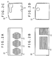
- the casing 10 is roughly rectangular parallelepiped in outside shape, has a hollow inside so as to cover apparatuses mounted on the fuel cell 1, and is opened on its bottom side.
- the casing 10 is provided with exhaust ports 11, 12 and 13, and intake ports 14, 15, and an end portion of the upper surface of the casing 10 is an inclined surface extending toward a side surface provided with the exhaust ports 11, 12 and 13.
- the exhaust ports 11 and the exhaust ports 12, 13 are adjacently formed in one side surface of the casing 10, and air made to flow in the fuel cell 1 for cooling the power generation unit 30 and air after the power generation reaction by the power generation unit 30 are discharged respectively through the exhaust ports 11 and the exhaust ports 12, 13.
- the exhaust ports 11 are air outlets through which air for releasing heat from radiation fins 33 (described later) is to be discharged. Further, the exhaust ports 11 are opened in a roughly rectangular shape in the side surface of the casing 10, and are formed in plurality in the vertical direction.
- the exhaust ports 12, 13 are air outlets through which air supplied to the power generation unit 30 at the time of power generation in the power generation unit 30 is to be discharged, are opened in rectangular shape in the side surface of the casing 10, and are formed in plurality in the vertical direction along the exhaust ports 11.
- the exhaust ports 11, 12, 13 are formed so that their longitudinal sizes are sequentially shortened along the upward and downward directions of the side surface of the casing 10.
- the intake ports 14, 15 are formed in a side surface opposite to the side surface of the casing 10 in which the exhaust ports 11 and the exhaust ports 12, 13 are formed, of the casing 10, and air for cooling the power generation unit 30 and air containing oxygen served to the power generation reaction by the power generation unit 30 are taken through the intake ports 14, 15 into the fuel cell 1.
- the intake ports 14 are air intake ports through which air for releasing heat from the radiation fins 33 (described later) is to be taken into the fuel cell 1, are opened in a roughly rectangular shape in the side surface of the casing 10, and are formed in plurality in the vertical direction.
- the intake ports 15 are air intake ports for taking in air supplied to the power generation unit 30 at the time of power generation by the power generation unit 30, are similarly opened in a roughly rectangular shape in the side surface of the casing 10, and are formed in plurality in the vertical direction along the intake ports 14.
- one end face of the casing 10 can be provided with connection holes 16 through which wires for transmission of various signals between the fuel cell 1 and the exterior are to be passed. Furthermore, the other end face can also be provided with required connection holes 18.
- control substrate 20 is provided with a control circuit for controlling the apparatuses constituting the fuel cell 1, and the control substrate 20 is disposed on the upper side of the power generation unit 30.
- the details of the control circuit are not shown in the figure.
- commands concerning the control of the driving of the cooling fan 51 and the air supply fans 52, 53, or a control circuit for opening and closing operations of the hydrogen purge valve 54, a voltage conversion circuit such as a DC/DC converter for raising the voltage outputted from the power generation unit 30, and further commands concerning the driving of various apparatuses by picking up various environmental conditions such as temperature and humidity detected by sensors (described later) can be performed by circuits mounted on the control substrate 20.
- control substrate 20 is disposed in the fuel cell 1 in the fuel cell 1 according to this embodiment, the control substrate 20 may be disposed in the exterior of the fuel cell 1; for example, various electronic apparatuses supplied with electric power for driving from the fuel cell 1 may include the control substrate 20.
- the power generation unit 30 will be described in detail below referring to Figs. 1, 3, 4, 5A and 5B.
- the power generation unit 30 has a roughly rectangular parallelepiped shape, wherein a part of the side surface opposite to the side surface 39 fronting on the cooling fan 51 and the air supply fans 52, 53 is cut out in a rectangular shape along the vertical direction of the power generation unit 30, and the power generation unit 30 is placed on a base 57.
- the cooling fan 51 and the air supply fans 52, 53 are adjacently disposed along the side surface 39 of the power generation unit 30.
- the cooling fan 51 thus disposed radiates heat from the radiation fins 33.
- the air supply fans 52, 53 are so disposed as to front on opening portions 34, and air is made to flow in the power generation unit 30 through the opening portions 34.
- the power generation unit 30 in this embodiment has joint bodies 32 sandwiched between nine separators 31, and eight power generation cells for performing power generation are connected in series with each other.
- Each of the power generation cells can output a voltage of about 0.6 V. Therefore, the power generation unit 30 as a whole can output a voltage of 4.8 V.
- the power generation unit 30 can pass a current of about 2 A, and the output power is ideally 9.6 W; due to heat generation during the power generation reaction and the like factors, the actual output power is about 6.7 W, which is about 70% of the ideal output power.
- the output power can be further enhanced, by regulation of the amount of water contained in the joint bodies 32 or smooth supply of hydrogen gas to the power generation unit 30 as will be described later.
- the number of the power generation cells constituting the power generation unit 30 is not limited to eight in this embodiment, and the power generation unit 30 may be composed of a required number of power generation cells according to the output power necessary for driving the various electronic apparatuses.
- the opening portions 34 formed in the separators 31 front on the side surface 39 of the power generation unit 30, and the side surface on the opposite side of the side surface 39 of the power generation unit 30 is also provided with opening portions 40 corresponding respectively to the opening portions 34, as will be described later. Supply and exhaust of air containing oxygen to and from the power generation unit 30 are performed by way of the opening portions 34 and the opening portions 40 fronting on the side surface on the opposite side of the side surface 39 on which the opening portions 34 front.
- the joint body 32 sandwiched between the separators 31 is composed of a solid state polymer electrolyte membrane 36 showing ionic conductivity when moistened, and electrodes 37 clamping the solid state polymer electrolyte membrane 36 therebetween.
- a sealing member 35 for sealing between the separator 31 and the joint body 32 upon formation of a stack structure is disposed near the peripheral edges of the joint body 32. It suffices for the sealing member 35 to be formed from a material which can sufficiently insulate the peripheral portion of the separator 31 and the peripheral portion of the joint body 32 from each other.
- the solid state polymer electrolyte membrane 36 there can be used, for example, a sulfonic acid-based solid polymer electrolyte membrane.
- the electrode 37 an electrode supporting thereon a catalyst such as platinum for accelerating the power generation reaction may be used.
- the power generation cell constituting the power generation unit 30 is composed of two separators 31 and the joint body 32 sandwiched between the separators 31; for example, two power generation cells 50 to be connected in series with each other are shown in Fig. 4.
- the separator 31 constituting the power generation unit 30 includes a conduit 43, a conduit 38 formed on the back side of the surface provided with the conduit 43 of the separator 31, a supply hole 42 and a discharge hole 41 connected to the conduit 43, a connection portion 45 for connection between the conduit 43 and the supply hole 42, a connection portion 46 for connection between the conduit 43 and the discharge hole 41, and a radiation fin 33.
- the conduit 43 is an in-plane conduit for causing hydrogen gas as a fuel gas to flow in the plane of the separator 31.
- the conduit 43 is so formed as to meander in the surface of the separator 31 for enhancing the efficiency of the power generation reaction, and is so shaped as to supply the hydrogen gas to the whole part of the electrode 37.
- the supply hole 42 is a hydrogen gas conduit in supplying the hydrogen gas from a hydrogen gas storage unit such as the hydrogen occlusion cartridge 60 provided in the exterior of the power generation unit 30 into the conduit 43.
- the connection portion 45 connects the conduit 43 and the supply hole 42 to each other, for supplying the hydrogen gas into the conduit 43.
- connection portion 46 connects the conduit 43 and the discharge hole 41 to each other, for discharging the hydrogen gas after the power generation reaction from the conduit 43.
- the sectional areas of the connection portions 45, 46 are smaller than the sectional area of the conduit 43 upon formation of the stack structure from the separators 31 and the joint bodies 32; for example, the widths of the connection portions 45, 46 are smaller than the width of the conduit 43.
- the width of the connection portion 45 is smaller than the width of the connection portion 46, and the width of the conduit 43 is smaller on the inlet side than on the outlet side.
- the supply hole 42 and the discharge hole 41 are connected between the separators 31 which are laminated upon formation of the stack structure, for forming a supply passage for supplying the hydrogen gas to each separator 31 and a discharge passage for discharging the hydrogen gas after power generation.
- the discharge passage is opened to the atmosphere by the hydrogen purge valve 54 which will be described later, whereby a pressure difference is generated in the water accumulated in the conduit 43 between the supply passage side and the discharge passage side, and the water can be discharged by the pressure difference.
- the conduits 38 are formed on the back side of the surface provided with the conduit 43 of the separator 31, and constitutes passages for causing air containing oxygen to flow into the conduits 38.
- the conduits 38 are so formed as to extend in the width direction of the separator 31, are opened at side edge portions of the separator 31, and are formed in plurality along the longitudinal direction of the separator 31.
- oxygen-containing air is supplied and exhausted into and from the conduits 38 through opening portions 34, 40 by which the conduits 38 are opened respectively at end portions of the separator 31.
- the widths of the opening portions 34, 40 are set larger than the width of the conduits 38.
- the width of the conduits 38 is narrowed in a taper form along the directions from the opening portions 34, 40 toward the depth of the conduit 38, whereby conduit resistance against air can be reduced so that air can flow smoothly at the time of intake of air into the conduit 38 or discharge of air from the conduit 38.
- the opening widths in the height direction of the opening portions 34, 40 are also set greater than that of the conduit 38, and the opening widths are narrowed in a taper form along the depth direction of the conduit 38 in the longitudinal direction and the sideways direction of the opening portions 34, 40, whereby the conduit resistance can be further reduced.
- a water-absorptive material having a water-absorbing property is disposed in the conduits 38, and the water-absorptive material is drawn out to the exterior of the separator 31, whereby water accumulated in the conduits 38 can be sucked out to the exterior of the separator 31.
- a separator 70 having a structure as shown in Figs. 6A and 6B can also be used.
- Fig. 6A is a sectional view showing the structure of the separator 70, in which the separator 70 includes an upper-side plate-like portion 71, a heat transfer portion 72 and a lower-side plate-like portion 73, with a sealing member 74 clamped between the upper-side plate-like portion 71 and the lower-side plate-like portion 73 so as to prevent the fuel gas from leaking from the conduits.
- the sealing member 74 may be formed of a material higher in thermal conductivity than the material constituting the upper-side plate-like portion 71 and the lower-side plate-like portion 73, whereby the heat-radiating effect for radiating heat from the separator 70 can be enhanced.
- a sealing member having a member with a high thermal conductivity embedded in a resin is preferably used; for example, such a sealing member as CHO-THERM (commercial name of a product by Taiyo wire cloth co., Ltd.) can be used.
- the heat transfer portion 72 is formed to extend to the radiation fin 75, for radiating the heat upon power generation from the separator 70. Further, the heat transfer portion 72 is formed of a material higher in thermal conductivity than the material constituting the upper-side plate-like portion 71 and the lower-side plate-like portion 73, whereby the heat-radiating characteristics of the separator 70 can be enhanced.
- the material constituting the heat transfer portion 72 there can be used, for example, copper, which is a metal having a comparatively high thermal conductivity. Further, oxygen-free copper enhanced in corrosion resistance and a copper plate which has been surface treated to enhance corrosion resistance may also be used.
- the lower-side plate-like portion 73 is provided with conduit 79 extending in the direction perpendicular to the plane of the drawing, as conduits in which oxygen-containing air flows.
- the sealing member 74 is sandwiched between the upper-side plate-like portion 71 and the lower-side plate-like portion 73 at end portions of the separator 70, whereby the heat transfer portion 72 is sealed from the exterior, and the heat transfer portion 72 is restrained from deterioration by the power generation reaction.
- Figs. 7A to 7C are plan views of the upper-side plate-like portion 71, the heat transfer portion 72 and the lower-side plate-like portion 73 which constitute the separator 70.
- the upper-side plate-like portion 71 is provided with a conduit 78 for flow of hydrogen gas.
- the conduit 78 is formed to meander in the plane so as to permit the hydrogen gas to flow over the entire area of the plane.
- the upper-side plate-like portion 71 is provided with a supply hole 77a for supplying the hydrogen gas into the conduit 78 and a discharge hole 76a for discharging the hydrogen gas after the power generation reaction.
- a supply hole 77a for supplying the hydrogen gas into the conduit 78
- a discharge hole 76a for discharging the hydrogen gas after the power generation reaction.
- the heat transfer portion 72 is roughly plate-like, and is fitted into the lower-side plate-like portion 73.
- the heat transfer portion 72 is extended to a radiation fin 75, to radiate heat from the separator 70.
- the sealing member 74 is disposed at an end portion of the lower-side plate-like portion 73 so as to insulate the heat transfer portion 72 from the exterior, and the heat transfer portion 72 is sandwiched by the lower-side plate-like portion 73 and the upper-side plate-like portion 71 to form the separator 70 as an integral body.
- the sealing member 74 is provided with a supply hole 77b and a discharge hole 76b matched in position to the supply hole 77a and the discharge hole 76a.
- the lower-side plate-like portion 73 are also provided with hole portions matched to the supply holes 77a, 77b and the discharge holes 76a, 76b, whereby a supply hole and a discharge hole which are integrated upon assembly of the separator 70 can be formed. Furthermore, as shown in Fig. 7C, a conduit 79 for flow of oxygen-containing air is provided on the back side of the lower-side plate-like portion 73. Also, a supply hole 77c for supplying hydrogen gas into the conduit 78 and a discharge hole 76c for discharging the hydrogen gas are provided.
- the fuel cell 1 has the cooling fan 51 and the air supply fans 52, 53 adjacently disposed along the side surface 39, on which the opening portions 34 front, of the power generation unit 30, as has been described above. Further, the fuel cell 1 has a temperature sensor 64 for detecting the temperature of air taken in from the exterior of the fuel cell 1 by the cooling fan 51 and a humidity sensor 65 for detecting the humidity of the air, and a temperature sensor 61 for detecting the temperature of air discharged from the power generation unit 30 by the air supply fans 52, 53 and a humidity sensor 62 for detecting the humidity of the air. In addition, the power generation unit 30 has a temperature sensor 63 for detecting the temperature of the power generation unit 30.
- the cooling fan 51 causes the air taken in through the intake ports 14 to flow from the intake ports 14 to the exhaust ports 11, and discharges the air to the exterior of the fuel cell 1.
- the cooling fan 51 is disposed between the intake ports 14 and the exhaust ports 11, and the radiation fin 33 disposed between the cooling fan 51 and the intake ports 14 radiates heat by the function of the air made to flow by the cooling fan 51.
- the flow of the air is not limited to the vicinity of the radiation fin 33, and the air may be made to flow in the entire region of the inside of the fuel cell 1 to thereby cool the power generation unit 30.
- the air supply fans 52, 53 causes air to flow to the intake ports 15, the power generation unit 30 and the exhaust ports 12, 13.
- the air supply fans 52, 53 causes the air taken in through the intake ports 15 to flow to the power generation unit 30, and discharges the air discharged after the power generation reaction in the power generation unit 30 to the exterior of the fuel cell 1 through the exhaust ports 12, 13.
- the power generation unit 30 is provided with the conduit 38 and the opening portions 34, 40 as has been described above referring to Figs. 3, 5A and 5B, and the air supply fans 52, 53 form the flows of air from the intake ports 15 to the conduit 38 and the exhaust ports 12, 13 as indicated by arrows in the figure.
- the flow of air generated by the cooling fan 51 and the flows of air generated by the air supply fans 52, 53 can be made to be airflows independent from each other. Therefore, by driving the cooling fan 51 and the air supply fans 52, 53 independently, it is possible to independently perform the cooling of the power generation unit 30 and the supply and discharge of air to and from the power generation unit 30.
- the layout of the cooling fan 51 and the air supply fans 52, 53 in the fuel cell 1 in this embodiment is not limitative; the cooling fan 51 and the air supply fans 52, 53 may be so disposed as to front on opening portions formed in side surfaces of a plurality of power generation units so as to supply and exhaust air, whereby the supply and exhaust of air can be performed collectively for the plurality of power generation units.
- air can be made to flow in the reverse direction by reversely rotating the cooling fan 51 and the air supply fans 52, 53.
- the temperature sensors 61, 64, the humidity sensors 62, 65 and the temperature sensor 63 are provided for respectively detecting the temperature and humidity of air taken in through the intake ports 14, the temperature and humidity of air discharged through the exhaust ports 12, 13, and the temperature of the power generation unit 30.
- the temperature sensor 63 is disposed in the vicinity of a roughly central portion of the power generation unit 30, and detects the temperature of the power generation unit 30 at the time of power generation in the power generation unit 30.
- the temperature sensor 64 and the humidity sensor 65 are disposed in the vicinity of the intake ports 14 as not to block the conduit for the air taken in through the intake ports 14.
- the temperature sensor 61 and the humidity sensor 62 are disposed on the air outlet side of the power generation unit 30 fronting on the air supply fans 52 and 53 so as not to hinder the flow of air.
- the driving of the cooling fan 51 is controlled based on the data concerning the temperature of the power generation unit 30 detected by the temperature sensor 63, and the power generation unit 30 is driven under a preferable temperature condition.
- the fuel cell 1 may include a pressure sensor for detecting the pressure of air supplied and exhausted, in addition to the temperature and humidity sensors.
- the relative humidity of the air taken in through the intake ports 14 is calculated based on the temperature and humidity detected by the temperature sensor 64 and the humidity sensor 65, and the relative humidity of the air discharged through the exhaust ports 12, 13 is calculated based on the temperature and humidity detected by the temperature sensor 61 and the humidity sensor 62.
- the quantity of water produced by the power generation reaction can be calculated based on the output power generated by the power generation unit 30. Therefore, by determining the difference between the quantity of water discharged from the fuel cell 1 and the quantity of water generated by the power generation reaction, it is possible to calculate the amount of water remaining in the power generation unit 30.
- a stable power generation reaction can be performed by setting the joint bodies 32 constituting the power generation unit 30 into an appropriately moistened state; therefore, stable power generation can be achieved by driving the air supply fans 52, 53 on the basis of the data concerning the amount of water remaining in the power generation unit 30.
- the rotating speeds of the air supply fans 52, 53 are raised, whereby the excessive water can be discharged from the power generation unit 30 together with air.
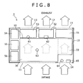
- the control of the temperature of the power generation unit 30 and the amount of water remaining in the power generation unit 30 will be described in detail, referring to Fig. 9.
- the axis of abscissas indicates the temperature of the power generation unit 30, and the axis of ordinates indicates the amount of water remaining in the power generation unit 30.
- the environmental condition represented by A in the figure is an environmental condition in which the temperature of the power generation unit 30 is higher and the amount of water remaining in the power generation unit 30 is larger as compared with the environmental condition in the stable region, and it is necessary in the environmental condition A to cool the power generation unit 30 and to reduce the amount of water remaining there.
- the amount of water remaining in the power generation unit 30 is reduced by raising the rotating speeds of the air supply fans 52, 53 and the power generation unit 30 is further cooled by raising the rotating speed of the cooling fan 51, whereby the temperature and the water amount are controlled from the environmental condition A into the stable region in which stable power generation can be achieved.
- the environmental condition represented by B in the figure is an environmental condition in which the temperature of the power generation unit 30 is lower and the amount of water remaining in the power generation unit 30 is larger as compared with the stable condition.
- the amount of water remaining in the power generation unit 30 is reduced by raising the rotating speeds of the air supply fans 52, 53 and the cooling of the power generation unit 30 is suppressed by lowering the rotating speed of the cooling fan 51, whereby the temperature of the power generation unit 30 and the amount of water therein are controlled from the environmental condition B into the stable region in which stable power generation can be achieved.
- the environmental condition represented by C in the figure is an environmental condition in which the temperature of the power generation unit 30 is lower and the amount of water remaining in the power generation unit 30 is smaller as compared with the stable condition.
- the discharge of water produced in the power generation unit 30 is reduced by lowering the rotating speeds of the air supply fans 52, 53 and the cooling of the power generation unit 30 is suppressed by lowering the rotating speed of the cooling fan 51.
- the temperature of the power generation unit 30 and the amount of water therein are controlled from the environmental condition C into the stable region in which stable power generation can be achieved.
- the environmental condition represented by D in the figure is an environmental condition in which the temperature of the power generation unit 30 is higher and the amount of water remaining in the power generation unit 30 is smaller as compared with the stable condition.
- the discharge of water produced in the power generation unit 30 is reduced by lowering the rotating speeds of the air supply fans 52, 53 and the power generation unit 30 is further cooled by raising the rotating speed of the cooling fan 51.
- the temperature of the power generation unit 30 and the amount of water therein are controlled from the environmental condition D into the stable region in which stable power generation can be achieved.
- the hydrogen purge valve 54, the regulator 55 and the manual valve 56 will be described below, referring to Figs. 1, 4, 5A and 5B.
- the hydrogen purge valve 54, the regulator 55 and the manual valve 56 are adjacently laid out along an end face of the power generation unit 30.
- a region for arranging various apparatuses can be secured on the end face side of the power generation unit 30, and the apparatuses for stable driving of the fuel cell 1 can be contained in a compact form.
- the hydrogen purge valve 54 as a water discharge means for discharging the water accumulated in the conduit 43 can discharge the water from the conduit 43 by opening to the atmosphere the discharge passage connected to the conduit 43.
- a pressure difference is generated between the pressure exerted on the water accumulated in the conduit 43 by the hydrogen gas on the supply passage side and the pressure exerted by the atmospheric air on the discharge passage side. Due to the pressure difference, the water accumulated in the conduit 43 is discharged from the conduit 43.
- the hydrogen purge valve 54 can be driven by a drive system using an electromagnetic force, for example, or electric power for driving the hydrogen purge valve 54 may be supplied from the power generation unit 30.
- the regulator 55 as a pressure control means for controlling the pressure of the hydrogen gas regulates the pressure of the hydrogen gas supplied from the hydrogen occlusion cartridge 60 to a required pressure, thereby feeding out the hydrogen gas to the power generation unit 30.
- the regulator 55 can supply the hydrogen gas to the power generation unit 30 while lowering the pressure of the hydrogen gas to a pressure of about 0.05 to 0.10 MPa.
- the manual valve 56 as a gas supply means for supplying the hydrogen gas to the power generation unit 30 opens the conduit for supplying the hydrogen gas from the hydrogen occlusion cartridge 60 to the power generation unit 30 at the time of performing power generation in the power generation unit 30.
- the hydrogen purge valve 54, the regulator 55 and the manual valve 56 are important for causing the fuel cell 1 to perform stable power generation, and these apparatuses are contained in the fuel cell 1 in a compact form, whereby the overall size of the fuel cell 1 can be reduced.
- Figs. 10 to 12 are respectively a back view, a side view, and a face view of a separator portion in this embodiment.
- the separator 81 is provided on its back side with grooves 83 for constituting conduits for oxygen, and on its face wide with a groove 86 for constituting a conduit for hydrogen.
- the separators 81 may be disposed with the back side on the face side, when laminated with the power generation body (not shown) sandwiched therebetween.
- the separator 81 is provided in its oxygen supply side surface with a plurality of grooves 83 extended rectilinearly in the width direction of the separator 81, and the grooves 83 are extended in parallel to each other, so that the grooves 83 and rib portions 82 are alternately located along the longitudinal direction of the separator 81.
- the length L6 in the longitudinal direction of the separator 81 formed in a roughly flat plate-like shape is 79.5 mm, and the width L8 orthogonal thereto is 41 mm.
- the grooves 83 are opened to be wider at both end portions of the separator 81. As for specific sizes, in Fig.
- the width L1 of a central portion extended in parallel of the groove 83 is 2 mm
- the width L2 of the rib portion 82 adjacent to the groove 83 is also 2 mm.
- the groove 83 is opened in a tapered shape at both end portions where they are wider, and the start position L0 of the tapered portion which is formed also in the thickness direction of the separator 81 is 8 mm from the end portion, and the taper is inclined at an angle of 2.15° starting from the start position L0.
- the opening width is enlarged by about 1 mm in the in-plane direction, the width L3 at the end portion of the groove 83 is 3 mm, while the width L4 of the rib portion 82 adjacent thereto is tapered to 1 mm.
- the tapering start position L9 of the rib portion 82 is 5.5 mm from the end portion.
- the opening width L5 in the vicinity of the center is 2.5 mm due to the influence of screw holes, and the width L10 in the longitudinal direction of a power generation body holding region continuous with the heat radiation portion 84 is 56.5 mm (see Fig. 11), and the interval L7 between the screw holes is 54.5 mm.
- the thickness T1 of the heat radiation portion 84 is 1.3 mm
- the thickness T2 in the power generation holding region where the grooves 83, 86 are formed is 2.3 mm.
- the hydrogen supply side surface 87 of the separator 81 is provided with the groove 86 extended in a meandering pattern for going and returning five times between a hydrogen supply hole 89 and a hydrogen discharge hole 88, the meandering groove 86 has a depth of 0.6 mm and a width L12 of 1.0 mm, and the radius of curvature at the turning-back portions is 0.9 mm (inside radius), 1.9 mm (outside radius).
- the groove 86 becomes thinner at connection portions for connection with the hydrogen supply hole 89 and the hydrogen discharge hole 88; the hydrogen supply hole 89 and the hydrogen discharge hole 88 are sized to have a width of 1.5 mm, with the position of 2.25 mm from the end portion in the longitudinal direction of the separator 81 as a center, and the start position L17 of the thinner groove from the end portion in the longitudinal direction of the separator 81 is 6 mm, so that the length is about 3 mm.
- the width L11 of the groove at the connection portions 90 is 0.5 mm
- the position L15 of the connection portion 90 on the side of the hydrogen discharge hole 88 from the end portion in the width direction of the separator 81 is 7.9 mm in terms of center position
- the position L16 of the connection portion 90 on the side of the hydrogen supply hole 89 is 33.1 mm in terms of center position.
- the turning-back position L13 from the end portion on the side closer to the hydrogen supply hole 89 and the hydrogen discharge hole 88 in the longitudinal direction of the separator 81 is 7 mm.
- the length L14 between the turning-back portions of the groove 86 is 42 mm.
- Fig. 13 is a plan view of the fuel cell apparatus 100 in this embodiment.
- the fuel cell apparatus 100 has a stack structure in which the separators 81 and the power generation bodies are stacked.
- the plate-like portion disposed at the uppermost portion constituting the stack structure is seen through, and the groove 86 formed in the surface of the separator in the region where the power generation unit 99 is disposed is indicated by broken lines in the figure.
- the length L18 obtained by summing up the size in the longitudinal direction of the separator for forming the power generation unit 99 and the size in the longitudinal direction of the heat radiation portion extended in the longitudinal direction from the separator is 78 mm, and the width L8 of the separator is 41 mm.
- An end portion of a heat radiation portion 84 is rectilinear in the figure, but may be provided with notches or cutouts for passing wires therethrough.
- a casing 91 for constituting the fuel cell apparatus 100 and for containing the units inclusive of the power generation unit 99 has a length L21 in the longitudinal direction of 95.5 mm and a width L20 of 57 mm.
- the fuel cell apparatus 100 in this embodiment has a length in the longitudinal direction on plane of 95.5 mm and a width of 57 mm.
- Fig. 14 is a side view, as viewed from a lateral side, of the fuel cell apparatus 100 in the condition where the casing 91 has been removed.
- the power generation unit 99 has a stack structure in which nine separators 81 are stacked, with the power generation bodies 96 sandwiched therebetween, and has a structure in which eight power generation cells are connected in series with each other.
- the power generation unit 99 is disposed on a base 98 which constitutes a bottom portion of the fuel cell apparatus 100.
- the height T4 from the bottom surface of the base 98 to the surface of a plate-like portion disposed at the uppermost portion of the power generation unit 99 is 34.62 mm.
- the height T5 from the bottom surface of the base 98 to the center in the thickness direction of the separator 81 located at a central portion of the power generation unit 99 is 17.78 mm, which is approximately equal to the heights from the bottom surface of the base 98 to the centers of a cooling fan 92 and air supply fans 93, 94 disposed on the side of a side surface of the power generation unit 99.
- the height T6 of the power generation unit 99 obtained by summing up the thickness of a base 95, the plate-like portion 97, and the stacked separators 81 and power generation bodies 96 is 29.62 mm.
- the height of the cooling fan 92 is approximately equal to the height between the heat radiation portion 84 disposed at the uppermost portion of the power generation unit 99 and the heat radiation portion 84 disposed at the lowermost portion, so that air for cooling can be supplied to the entire part of the heat radiation portions 84.
- the height of the air supply fans 93, 94 is approximately equal to the height between the grooves 82 at the uppermost portion of the power generation unit 99 and the grooves 82 at the lowermost portion, so that oxygen-containing air can be sufficiently supplied to the entire part of the grooves 82.
- the fuel cell according to the present invention can contain in a compact form the various apparatuses for driving the fuel cell, and is preferable for use as a power source for supplying electric power for driving a portable electronic apparatus such as a notebook type personal computer, a cellular phone and a PDA.
- a portable electronic apparatus such as a notebook type personal computer, a cellular phone and a PDA.
- the application of the fuel cell 1 according to the present invention is not limited to these portable electronic apparatuses, and the fuel cell 1 can be utilized as a power source for driving various electronic apparatuses.
- the fuel cell of the present invention by performing restraint of the temperature rise in the power generation unit and control of the amount of water remaining in the power generation unit, it is possible to achieve stable power generation without causing a trouble in power generation, such as dry-up. Further, the control of the temperature of the power generation unit and the control of the amount of water remaining in the power generation unit can be independently performed accurately, so that it is possible to provide a fuel cell which is high in reliability. In addition, according to such a fuel cell, various apparatuses for performing power generation can be contained in the fuel cell in a compact form, so that the fuel cell can be reduced in size.
- driving by a fuel cell can be achieved even for a portable electronic apparatus by mounting thereon the fuel cell sized for portable use, and the fuel cell can be mounted on a required electronic apparatus.
Landscapes
- Engineering & Computer Science (AREA)
- Chemical & Material Sciences (AREA)
- Life Sciences & Earth Sciences (AREA)
- Manufacturing & Machinery (AREA)
- Sustainable Development (AREA)
- Sustainable Energy (AREA)
- Chemical Kinetics & Catalysis (AREA)
- Electrochemistry (AREA)
- General Chemical & Material Sciences (AREA)
- Combustion & Propulsion (AREA)
- Fuel Cell (AREA)
Applications Claiming Priority (3)
| Application Number | Priority Date | Filing Date | Title |
|---|---|---|---|
| JP2002361449 | 2002-12-12 | ||
| JP2002361449A JP4292368B2 (ja) | 2002-12-12 | 2002-12-12 | 燃料電池及びこれを搭載した電子機器 |
| PCT/JP2003/014977 WO2004054026A1 (ja) | 2002-12-12 | 2003-11-25 | 燃料電池及びこれを搭載した電子機器 |
Publications (2)
| Publication Number | Publication Date |
|---|---|
| EP1571722A1 true EP1571722A1 (de) | 2005-09-07 |
| EP1571722A4 EP1571722A4 (de) | 2009-01-28 |
Family
ID=32501047
Family Applications (1)
| Application Number | Title | Priority Date | Filing Date |
|---|---|---|---|
| EP03774186A Withdrawn EP1571722A4 (de) | 2002-12-12 | 2003-11-25 | Brennstoffzelle und elektronische ausrüstung zu deren montage |
Country Status (9)
| Country | Link |
|---|---|
| US (1) | US8101311B2 (de) |
| EP (1) | EP1571722A4 (de) |
| JP (1) | JP4292368B2 (de) |
| KR (1) | KR101107649B1 (de) |
| CN (1) | CN100444447C (de) |
| AU (1) | AU2003284661A1 (de) |
| CA (1) | CA2508457C (de) |
| TW (1) | TWI238558B (de) |
| WO (1) | WO2004054026A1 (de) |
Cited By (1)
| Publication number | Priority date | Publication date | Assignee | Title |
|---|---|---|---|---|
| US10218011B2 (en) | 2011-10-28 | 2019-02-26 | Commissariat à l'énergie atomique et aux énergies alternatives | High-temperature or fuel-cell electrochemical system having improved thermal management |
Families Citing this family (20)
| Publication number | Priority date | Publication date | Assignee | Title |
|---|---|---|---|---|
| JP4329425B2 (ja) * | 2003-06-23 | 2009-09-09 | 株式会社ニコン | 電子機器およびカメラ |
| JP2006032007A (ja) * | 2004-07-13 | 2006-02-02 | Nissan Motor Co Ltd | 燃料電池 |
| JP4876533B2 (ja) * | 2005-10-31 | 2012-02-15 | 株式会社エクォス・リサーチ | 燃料電池スタック及びその制御方法 |
| US20070099047A1 (en) * | 2005-11-02 | 2007-05-03 | Chun-Chin Tung | Regulated fuel cell device |
| KR100806582B1 (ko) | 2006-07-07 | 2008-02-28 | 엘지전자 주식회사 | 연료 전지의 선택적 스택 단열장치 |
| JP5139850B2 (ja) * | 2008-03-14 | 2013-02-06 | 株式会社日立製作所 | 固体酸化物形燃料電池 |
| JP2009245818A (ja) * | 2008-03-31 | 2009-10-22 | Equos Research Co Ltd | 燃料電池装置 |
| JP2011520055A (ja) * | 2008-04-11 | 2011-07-14 | ゼネラル・エレクトリック・カンパニイ | 燃焼器部品及び製造方法 |
| JP2009283150A (ja) * | 2008-05-19 | 2009-12-03 | Toshiba Corp | 燃料電池 |
| US7662501B2 (en) * | 2008-06-30 | 2010-02-16 | Intel Corporation | Transpiration cooling and fuel cell for ultra mobile applications |
| JP5382325B2 (ja) * | 2009-04-13 | 2014-01-08 | スズキ株式会社 | 燃料電池を搭載した小型車両 |
| KR101090715B1 (ko) * | 2009-05-27 | 2011-12-08 | 현대자동차주식회사 | 연료전지의 공기 공급량 제어 방법 |
| JP5406622B2 (ja) * | 2009-08-07 | 2014-02-05 | 株式会社フジクラ | 燃料電池用双極板 |
| US20110136030A1 (en) * | 2009-12-03 | 2011-06-09 | Enerfuel, Inc. | High temperature pem fuel cell with thermal management system |
| JP5652719B2 (ja) * | 2011-05-02 | 2015-01-14 | スズキ株式会社 | 燃料電池車両 |
| GB2499417A (en) | 2012-02-15 | 2013-08-21 | Intelligent Energy Ltd | A fuel cell assembly |
| KR102120831B1 (ko) * | 2018-12-27 | 2020-06-09 | 레드원테크놀러지 주식회사 | 수소연료전지 시스템 |
| CN110931824B (zh) * | 2019-11-29 | 2021-08-31 | 中国第一汽车股份有限公司 | 一种燃料电池冷却液流量分配系统及其控制方法 |
| JP7405623B2 (ja) * | 2020-01-16 | 2023-12-26 | 株式会社Subaru | 燃料電池システムおよびその排気湿度推定方法 |
| CN111361858A (zh) * | 2020-03-15 | 2020-07-03 | 河北源泷科技有限公司 | 一种危险原料安全转移装置 |
Citations (3)
| Publication number | Priority date | Publication date | Assignee | Title |
|---|---|---|---|---|
| JPH01186768A (ja) * | 1988-01-19 | 1989-07-26 | Meidensha Corp | 電解液循環形二次電池の電極構造 |
| WO1999034467A2 (en) * | 1997-09-10 | 1999-07-08 | Lynntech, Inc. | Fuel cell system for low pressure operation |
| EP1030396A1 (de) * | 1998-09-04 | 2000-08-23 | Kabushiki Kaisha Toshiba | Brennstoffzelle des festpolymertyps |
Family Cites Families (28)
| Publication number | Priority date | Publication date | Assignee | Title |
|---|---|---|---|---|
| US4950566A (en) | 1988-10-24 | 1990-08-21 | Huggins Robert A | Metal silicide electrode in lithium cells |
| JPH0690881B2 (ja) | 1989-11-27 | 1994-11-14 | 工業技術院長 | 炭素質固体電解質材料およびこれを用いた固体電解質電池 |
| JP3553101B2 (ja) | 1993-03-15 | 2004-08-11 | 三菱重工業株式会社 | 固体高分子電解質燃料電池 |
| JPH0922719A (ja) * | 1995-07-05 | 1997-01-21 | Sanyo Electric Co Ltd | ポータブル燃料電池及びその運転方法 |
| JPH09312165A (ja) * | 1996-05-23 | 1997-12-02 | Aqueous Res:Kk | 燃料電池発電装置およびその運転方法 |
| JPH1064567A (ja) | 1996-06-14 | 1998-03-06 | Matsushita Electric Ind Co Ltd | 燃料電池用水素供給システム及び携帯用電気機器 |
| JPH10162842A (ja) | 1996-11-29 | 1998-06-19 | Matsushita Electric Works Ltd | 固体高分子型燃料電池用セパレータ、及びこれを用いた固体高分子型燃料電池スタック |
| US6277508B1 (en) * | 1998-07-17 | 2001-08-21 | International Fuel Cells Corporation | Fuel cell power supply with exhaust recycling for improved water management |
| JP3524802B2 (ja) * | 1999-02-24 | 2004-05-10 | 三洋電機株式会社 | 固体高分子型燃料電池 |
| JP2000256007A (ja) | 1999-03-11 | 2000-09-19 | Jsr Corp | プロトン伝導性材料の製造方法 |
| JP2000353536A (ja) | 1999-06-09 | 2000-12-19 | Nippon Telegr & Teleph Corp <Ntt> | 燃料電池及びその運転方法 |
| JP3416578B2 (ja) | 1999-06-25 | 2003-06-16 | 三洋電機株式会社 | 固体高分子電解質型燃料電池 |
| JP3485840B2 (ja) | 1999-06-30 | 2004-01-13 | 三洋電機株式会社 | 燃料電池システム |
| US6635378B1 (en) | 1999-08-16 | 2003-10-21 | Hybrid Power Generation System, Llc | Fuel cell having improved condensation and reaction product management capabilities |
| EP1249051B1 (de) * | 2000-01-19 | 2004-04-07 | Manhattan Scientifics, Inc. | Brennstoffzellenstapel mit kühlrippen und verwendung von expandiertem graphit in brennstoffzellen |
| JP2001250569A (ja) * | 2000-03-06 | 2001-09-14 | Toyota Motor Corp | 燃料電池及びその集電板 |
| JP2001256988A (ja) * | 2000-03-08 | 2001-09-21 | Toyota Motor Corp | 燃料電池システムおよび燃料電池の運転方法 |
| DE10037825A1 (de) * | 2000-08-03 | 2002-05-16 | Xcellsis Gmbh | Brennstoffzellensystem |
| WO2002027814A2 (en) * | 2000-09-28 | 2002-04-04 | Proton Energy Systems, Inc. | Regenerative electrochemical cell system and method for use thereof |
| JP4892777B2 (ja) * | 2000-10-20 | 2012-03-07 | ソニー株式会社 | 燃料電池を備えた電気で駆動される装置 |
| US20020155333A1 (en) * | 2001-01-19 | 2002-10-24 | Fitts Bruce B. | Apparatus and method for electrochemical cell components |
| JP2002231292A (ja) * | 2001-01-31 | 2002-08-16 | Daikin Ind Ltd | 燃料電池及び燃料電池駆動式冷却冷凍装置 |
| JP3882513B2 (ja) | 2001-03-05 | 2007-02-21 | 日産自動車株式会社 | 燃料電池の制御装置 |
| JP2002313381A (ja) * | 2001-04-19 | 2002-10-25 | Mitsubishi Heavy Ind Ltd | 燃料電池発電設備 |
| US6649290B2 (en) * | 2001-05-11 | 2003-11-18 | Cellex Power Products, Inc. | Fuel cell thermal management system and method |
| JP3894026B2 (ja) * | 2001-05-18 | 2007-03-14 | 株式会社デンソー | 燃料電池内部の水分測定方法 |
| JP2002352817A (ja) | 2001-05-25 | 2002-12-06 | Matsushita Electric Ind Co Ltd | 高分子電解質型燃料電池 |
| US6861167B2 (en) * | 2001-07-25 | 2005-03-01 | Ballard Power Systems Inc. | Fuel cell resuscitation method and apparatus |
-
2002
- 2002-12-12 JP JP2002361449A patent/JP4292368B2/ja not_active Expired - Lifetime
-
2003
- 2003-11-25 AU AU2003284661A patent/AU2003284661A1/en not_active Abandoned
- 2003-11-25 EP EP03774186A patent/EP1571722A4/de not_active Withdrawn
- 2003-11-25 KR KR1020057010694A patent/KR101107649B1/ko not_active IP Right Cessation
- 2003-11-25 WO PCT/JP2003/014977 patent/WO2004054026A1/ja active Application Filing
- 2003-11-25 US US10/536,599 patent/US8101311B2/en not_active Expired - Fee Related
- 2003-11-25 CN CNB2003801095634A patent/CN100444447C/zh not_active Expired - Fee Related
- 2003-11-25 CA CA2508457A patent/CA2508457C/en not_active Expired - Fee Related
- 2003-11-27 TW TW092133394A patent/TWI238558B/zh not_active IP Right Cessation
Patent Citations (4)
| Publication number | Priority date | Publication date | Assignee | Title |
|---|---|---|---|---|
| JPH01186768A (ja) * | 1988-01-19 | 1989-07-26 | Meidensha Corp | 電解液循環形二次電池の電極構造 |
| US6054228A (en) * | 1996-06-06 | 2000-04-25 | Lynntech, Inc. | Fuel cell system for low pressure operation |
| WO1999034467A2 (en) * | 1997-09-10 | 1999-07-08 | Lynntech, Inc. | Fuel cell system for low pressure operation |
| EP1030396A1 (de) * | 1998-09-04 | 2000-08-23 | Kabushiki Kaisha Toshiba | Brennstoffzelle des festpolymertyps |
Non-Patent Citations (1)
| Title |
|---|
| See also references of WO2004054026A1 * |
Cited By (1)
| Publication number | Priority date | Publication date | Assignee | Title |
|---|---|---|---|---|
| US10218011B2 (en) | 2011-10-28 | 2019-02-26 | Commissariat à l'énergie atomique et aux énergies alternatives | High-temperature or fuel-cell electrochemical system having improved thermal management |
Also Published As
| Publication number | Publication date |
|---|---|
| TWI238558B (en) | 2005-08-21 |
| US20050255340A1 (en) | 2005-11-17 |
| KR101107649B1 (ko) | 2012-01-20 |
| CN1745493A (zh) | 2006-03-08 |
| EP1571722A4 (de) | 2009-01-28 |
| US8101311B2 (en) | 2012-01-24 |
| AU2003284661A1 (en) | 2004-06-30 |
| KR20050085585A (ko) | 2005-08-29 |
| CA2508457C (en) | 2013-04-02 |
| JP4292368B2 (ja) | 2009-07-08 |
| JP2004193027A (ja) | 2004-07-08 |
| CN100444447C (zh) | 2008-12-17 |
| CA2508457A1 (en) | 2004-06-24 |
| WO2004054026A1 (ja) | 2004-06-24 |
| TW200423466A (en) | 2004-11-01 |
Similar Documents
| Publication | Publication Date | Title |
|---|---|---|
| CA2508457C (en) | Fuel cell and electronic equipment mounting it | |
| JP4042101B2 (ja) | 燃料電池および燃料電池を用いた電力供給方法 | |
| US20060105213A1 (en) | Separator, fuel cell device, and temperature control method for fuel cell device | |
| US8808938B2 (en) | Fuel cell system | |
| US20080138692A1 (en) | Fuel cell apparatus | |
| KR100990750B1 (ko) | 연료 전지 시스템 | |
| EP1498971A2 (de) | Kühlung einer luftgekühlten Brennstoffzellenanlage | |
| CN100533832C (zh) | 液体冷却燃料电池堆叠体 | |
| US20060046111A1 (en) | Semi-active full cell apparatus | |
| JP4839565B2 (ja) | 燃料電池システム | |
| US7314679B2 (en) | Air supply apparatus for a fuel cell | |
| JP6236108B2 (ja) | 燃料電池スタック | |
| JP5259146B2 (ja) | 燃料電池及び燃料電池システム | |
| JP2004311279A (ja) | 燃料電池、セパレータ、燃料電池の製造方法及び酸化剤の供給方法 | |
| JP2004192985A (ja) | 燃料電池用セパレータ及びこれを用いた燃料電池 | |
| JP2004281079A (ja) | セパレータ、燃料電池装置及び燃料電池装置の温度調整方法 | |
| EP2766948B1 (de) | Anordnung von gebläsen und leiterplatinen in brennstoffzellen-vorrichtungen | |
| JP2005235713A (ja) | 締結装置及び燃料電池 | |
| JP5007622B2 (ja) | 燃料電池及びこれを搭載した電子機器 | |
| JP4304575B2 (ja) | 燃料電池 | |
| JP6096740B2 (ja) | 燃料電池スタック | |
| JP2003142128A (ja) | 燃料電池 | |
| CN102214833A (zh) | 湿气交换器和燃料电池堆 |
Legal Events
| Date | Code | Title | Description |
|---|---|---|---|
| PUAI | Public reference made under article 153(3) epc to a published international application that has entered the european phase |
Free format text: ORIGINAL CODE: 0009012 |
|
| 17P | Request for examination filed |
Effective date: 20050610 |
|
| AK | Designated contracting states |
Kind code of ref document: A1 Designated state(s): AT BE BG CH CY CZ DE DK EE ES FI FR GB GR HU IE IT LI LU MC NL PT RO SE SI SK TR |
|
| AX | Request for extension of the european patent |
Extension state: AL LT LV MK |
|
| DAX | Request for extension of the european patent (deleted) | ||
| RBV | Designated contracting states (corrected) |
Designated state(s): DE FR GB |
|
| A4 | Supplementary search report drawn up and despatched |
Effective date: 20090105 |
|
| RIC1 | Information provided on ipc code assigned before grant |
Ipc: H01M 8/24 20060101ALI20081222BHEP Ipc: H01M 8/10 20060101ALI20081222BHEP Ipc: H01M 8/04 20060101AFI20040629BHEP |
|
| 17Q | First examination report despatched |
Effective date: 20091006 |
|
| STAA | Information on the status of an ep patent application or granted ep patent |
Free format text: STATUS: THE APPLICATION IS DEEMED TO BE WITHDRAWN |
|
| 18D | Application deemed to be withdrawn |
Effective date: 20150220 |