EP1571331A1 - Zündsteuerungssystem für eine Brennkraftmaschine - Google Patents
Zündsteuerungssystem für eine Brennkraftmaschine Download PDFInfo
- Publication number
- EP1571331A1 EP1571331A1 EP05003078A EP05003078A EP1571331A1 EP 1571331 A1 EP1571331 A1 EP 1571331A1 EP 05003078 A EP05003078 A EP 05003078A EP 05003078 A EP05003078 A EP 05003078A EP 1571331 A1 EP1571331 A1 EP 1571331A1
- Authority
- EP
- European Patent Office
- Prior art keywords
- cylinder
- basis
- ignition timing
- calculate
- knock
- Prior art date
- Legal status (The legal status is an assumption and is not a legal conclusion. Google has not performed a legal analysis and makes no representation as to the accuracy of the status listed.)
- Granted
Links
Images


Classifications
-
- E—FIXED CONSTRUCTIONS
- E03—WATER SUPPLY; SEWERAGE
- E03C—DOMESTIC PLUMBING INSTALLATIONS FOR FRESH WATER OR WASTE WATER; SINKS
- E03C1/00—Domestic plumbing installations for fresh water or waste water; Sinks
- E03C1/02—Plumbing installations for fresh water
- E03C1/08—Jet regulators or jet guides, e.g. anti-splash devices
- E03C1/086—Jet regulators or jet guides, easily mountable on the outlet of taps
-
- F—MECHANICAL ENGINEERING; LIGHTING; HEATING; WEAPONS; BLASTING
- F02—COMBUSTION ENGINES; HOT-GAS OR COMBUSTION-PRODUCT ENGINE PLANTS
- F02P—IGNITION, OTHER THAN COMPRESSION IGNITION, FOR INTERNAL-COMBUSTION ENGINES; TESTING OF IGNITION TIMING IN COMPRESSION-IGNITION ENGINES
- F02P5/00—Advancing or retarding ignition; Control therefor
- F02P5/04—Advancing or retarding ignition; Control therefor automatically, as a function of the working conditions of the engine or vehicle or of the atmospheric conditions
- F02P5/145—Advancing or retarding ignition; Control therefor automatically, as a function of the working conditions of the engine or vehicle or of the atmospheric conditions using electrical means
- F02P5/15—Digital data processing
- F02P5/152—Digital data processing dependent on pinking
- F02P5/1522—Digital data processing dependent on pinking with particular means concerning an individual cylinder
-
- E—FIXED CONSTRUCTIONS
- E03—WATER SUPPLY; SEWERAGE
- E03C—DOMESTIC PLUMBING INSTALLATIONS FOR FRESH WATER OR WASTE WATER; SINKS
- E03C1/00—Domestic plumbing installations for fresh water or waste water; Sinks
- E03C1/02—Plumbing installations for fresh water
- E03C1/10—Devices for preventing contamination of drinking-water pipes, e.g. means for aerating self-closing flushing valves
-
- F—MECHANICAL ENGINEERING; LIGHTING; HEATING; WEAPONS; BLASTING
- F02—COMBUSTION ENGINES; HOT-GAS OR COMBUSTION-PRODUCT ENGINE PLANTS
- F02D—CONTROLLING COMBUSTION ENGINES
- F02D35/00—Controlling engines, dependent on conditions exterior or interior to engines, not otherwise provided for
- F02D35/02—Controlling engines, dependent on conditions exterior or interior to engines, not otherwise provided for on interior conditions
- F02D35/023—Controlling engines, dependent on conditions exterior or interior to engines, not otherwise provided for on interior conditions by determining the cylinder pressure
- F02D35/024—Controlling engines, dependent on conditions exterior or interior to engines, not otherwise provided for on interior conditions by determining the cylinder pressure using an estimation
-
- F—MECHANICAL ENGINEERING; LIGHTING; HEATING; WEAPONS; BLASTING
- F02—COMBUSTION ENGINES; HOT-GAS OR COMBUSTION-PRODUCT ENGINE PLANTS
- F02D—CONTROLLING COMBUSTION ENGINES
- F02D35/00—Controlling engines, dependent on conditions exterior or interior to engines, not otherwise provided for
- F02D35/02—Controlling engines, dependent on conditions exterior or interior to engines, not otherwise provided for on interior conditions
- F02D35/025—Controlling engines, dependent on conditions exterior or interior to engines, not otherwise provided for on interior conditions by determining temperatures inside the cylinder, e.g. combustion temperatures
- F02D35/026—Controlling engines, dependent on conditions exterior or interior to engines, not otherwise provided for on interior conditions by determining temperatures inside the cylinder, e.g. combustion temperatures using an estimation
-
- F—MECHANICAL ENGINEERING; LIGHTING; HEATING; WEAPONS; BLASTING
- F02—COMBUSTION ENGINES; HOT-GAS OR COMBUSTION-PRODUCT ENGINE PLANTS
- F02D—CONTROLLING COMBUSTION ENGINES
- F02D35/00—Controlling engines, dependent on conditions exterior or interior to engines, not otherwise provided for
- F02D35/02—Controlling engines, dependent on conditions exterior or interior to engines, not otherwise provided for on interior conditions
- F02D35/028—Controlling engines, dependent on conditions exterior or interior to engines, not otherwise provided for on interior conditions by determining the combustion timing or phasing
-
- F—MECHANICAL ENGINEERING; LIGHTING; HEATING; WEAPONS; BLASTING
- F02—COMBUSTION ENGINES; HOT-GAS OR COMBUSTION-PRODUCT ENGINE PLANTS
- F02P—IGNITION, OTHER THAN COMPRESSION IGNITION, FOR INTERNAL-COMBUSTION ENGINES; TESTING OF IGNITION TIMING IN COMPRESSION-IGNITION ENGINES
- F02P5/00—Advancing or retarding ignition; Control therefor
- F02P5/04—Advancing or retarding ignition; Control therefor automatically, as a function of the working conditions of the engine or vehicle or of the atmospheric conditions
- F02P5/145—Advancing or retarding ignition; Control therefor automatically, as a function of the working conditions of the engine or vehicle or of the atmospheric conditions using electrical means
- F02P5/15—Digital data processing
- F02P5/153—Digital data processing dependent on combustion pressure
-
- E—FIXED CONSTRUCTIONS
- E03—WATER SUPPLY; SEWERAGE
- E03C—DOMESTIC PLUMBING INSTALLATIONS FOR FRESH WATER OR WASTE WATER; SINKS
- E03C2201/00—Details, devices or methods not otherwise provided for
- E03C2201/70—Reducing or removing limescale at spout outlet
-
- Y—GENERAL TAGGING OF NEW TECHNOLOGICAL DEVELOPMENTS; GENERAL TAGGING OF CROSS-SECTIONAL TECHNOLOGIES SPANNING OVER SEVERAL SECTIONS OF THE IPC; TECHNICAL SUBJECTS COVERED BY FORMER USPC CROSS-REFERENCE ART COLLECTIONS [XRACs] AND DIGESTS
- Y02—TECHNOLOGIES OR APPLICATIONS FOR MITIGATION OR ADAPTATION AGAINST CLIMATE CHANGE
- Y02T—CLIMATE CHANGE MITIGATION TECHNOLOGIES RELATED TO TRANSPORTATION
- Y02T10/00—Road transport of goods or passengers
- Y02T10/10—Internal combustion engine [ICE] based vehicles
- Y02T10/40—Engine management systems
Definitions
- this invention provides an ignition timing control device for an internal combustion engine which causes an air/fuel mixture inside a cylinder to combust by means of ignition by a spark plug.
- the device comprises a programmable controller programmed to calculate a temperature and pressure in the cylinder on the basis of an operating state of the engine, calculate a limit ignition timing at which knock is not generated, on the basis of the temperature and the pressure in the cylinder, and control an ignition timing of the spark plug to the limit ignition timing at which knock is not generated.
- Fig. 10 is a block diagram showing the composition of a generated heat calculation block according to this invention.
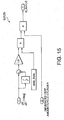
- Fig. 15 is a block diagram illustrating a process for calculating an amount of heat generated Q_burn , as implemented by a second generated heat calculation block according to this invention.
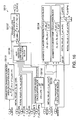
- Fig. 16 is a block diagram showing the composition of a cooling loss calculation block according to this invention.
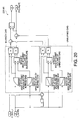
- Fig. 20 is a block diagram illustrating a process for calculating properties of the gas in the cylinder, as implemented by a gas properties calculation block according to this invention.
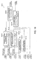
- Fig. 25 is a block diagram illustrating a process for calculating a knock generation index idx_kocr , as implemented by an integration block according to this invention.
- Fig. 27 is a block diagram illustrating a process for calculating an ignition timing ADV, as implemented by an ignition timing calculation unit according to this invention.
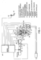
- the intake valve 15 is opened, the piston 6 descends, with the exhaust valve 16 in a closed state, and air is aspirated into the combustion chamber 5 from the intake manifold 3A.
- the fuel injector 21 injects gasoline fuel into the air taken into the cylinder. The fuel mixes with the intake air to form an air/fuel mixture that is aspirated into the combustion chamber 5.
- the exhaust valve 16 is driven by a cam installed on a cam shaft 26.
- the cam shaft 26 is coupled to the crank shaft 7 by means of a chain and a valve timing control (VTC) mechanism 28.
- VTC valve timing control
- the VTC mechanism 28 has a function of continually varying the opening and closing timing of the exhaust valve 16 in accordance with the angle of rotation of the crank shaft 7.
- the degree of opening of the intake throttle 23, the amount of fuel injected by the fuel injector 21 and the injection timing, the control of the open and close timing of the intake valve by the VTC mechanism 27, the control of the open and close timing of the exhaust valve by the VTC mechanism 28, and the ignition timing of the spark plug 14 are all controlled by means of an engine controller 50.
- the engine controller 50 specifies a target torque on the basis of a signal from the accelerator pedal depression sensor 42, and then specifies a target air volume in order to achieve this target torque.
- the engine controller 50 controls the degree of opening of the throttle 23, via the throttle motor 24, in such a manner that this target air volume is obtained.
- the engine controller 50 calculates the volume of air to be taken in to each cylinder during a four-stroke cycle of the engine 1, in other words, at every 7201 ⁇ 4 revolution of the engine 1, from the intake air volume measured by the air flow meter 32.
- the engine controller 50 controls the injection timing of the respective fuel injectors 21 on the basis of the crank angle determined by the crank angle sensor 33 and the angle of rotation of the cam as determined by the cam sensor 34, in such a manner that fuel is injected into each cylinder at the prescribed target injection timings.
- the engine controller 50 controls the ignition timing of the spark plug 14 in the following manner.
- combustion knock occurs when a time integral ⁇ 1 / ⁇ dt of the ignition delay 1 / ⁇ becomes 1.
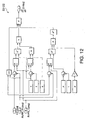
- the knock generation index calculation unit 53 comprises comparators 53001, 53004, 53005 and 53006, a counter 53002, a crank angle calculation block 53003, AND circuits 53007 and 53008, and a knock generation index calculation block 530.
- the output from the comparator 53001 is only unity in cases where the knock generation index calculation start request JOB_REQ is unity, and the previous value Z -1 is zero, in other words, when the knock generation index calculation start request is first issued. If the knock generation index calculation start request JOB_REQ remains at unity, then the output of the comparator 53001 becomes zero.
- the knock generation index calculation block 530 calculates a knock generation index ⁇ 1 / ⁇ dt and a mass combustion rate X_burn from the processed crank angle CA_calc(i) . The calculation involved is described later in detail.
- the calculation results of the knock generation index calculation block 530 are output in the form of a knock generation index combined with the counter output value i, idx_knocr(i) , and the mass combustion rate X_burn(i) .
- the outputs of the comparators 53004 and 53005 are processed by the AND circuit 53007.
- the AND circuit 53007 outputs a value of unity if the outputs of the comparators 53004 and 53005 are both unity, and it outputs a value of zero if either of these outputs is zero.
- the output of the AND circuit 53007 is stored in the ROM of the engine controller 50.
- the comparator 53006 compares the output value i of the counter 53002 with a predetermined number of crank angle calculations n_CA_calc .
- the comparator 53006 outputs a unity value, if the counter value i is less than the number of crank angle calculations n_CA_calc . If the counter value i has reached the number of crank angle calculations n_CA_calc , then it outputs a value of zero.
- the crank angle determined by the crank angle sensor 33 is used as the crank angle CA .
- the engine rotation speed determined by the crank angle sensor 33 is used as the crank speed NE .
- the fuel injection pulse width TP is calculated in accordance with the air intake flow rate Q measured by the air flow meter 32, and the engine speed NE determined by the crank angle sensor 33. A commonly known calculation method as disclosed in U.S. Patent No. 5,345,921 described above is used for this calculation.
- the ignition dead time IGNDEAD indicates the time from the output of an ignition signal by the engine controller 50 until actual ignition of the spark plug 14.
- the ignition dead time IGNDEAD depends on the engine speed NE, and it is determined by means of a commonly known calculation method as disclosed in U.S. Patent No. 6,557,526.
- the cylinder volume calculation block 53112 calculates the cylinder volume V_cyl using the following equation (2).
- V_cyl Vc + ⁇ 4 ⁇ D 2 ⁇ x_pis
- the combustion chamber surface area calculation block 53131 calculates the surface area of the combustion chamber 5 on the basis of the piston displacement x_pis .
- the average piston speed calculation block 53132 calculates the average piston speed on the basis of the engine speed NE.
- the gas properties calculation block 53133 calculates a specific heat ratio ⁇ on the basis of the mass combustion rate determined from the residual gas rate MRESFR and the cylinder temperature.
- the calculation method is the same at that used by the gas properties calculation block 53141 shown in Fig. 20. This calculation method is described hereinafter.
- the heat transfer coefficient calculation block 53136 calculates the heat transfer coefficient h in equation (8), on the basis of the cylinder pressure, the cylinder temperature, the average piston speed, the cylinder pressure, the initial cylinder temperature, the initial cylinder volume and the initial cylinder pressure.
- the cylinder temperature and pressure calculation block 5314 comprises a gas properties calculation block 53141, a total gas volume calculation block 53142, an adiabatic cylinder pressure calculation block 53143, an adiabatic cylinder temperature calculation block 53144, a cylinder temperature calculation block 53145, and a cylinder pressure calculation block 53146.
- the total gas volume calculation block 53142 calculates the total gas volume on the basis of the fuel injection pulse width TP, the constant KCONST and the target air/fuel ratio TABYF .
- the reset flag setting block 5321 sets the reset flag to ON if the crank angle CA has exceeded the basic ignition timing MBTCAL .
- the crank angle calculation block 541 determines the crank angle at knock CA_knk from the knock generation index idx_kocr(i) and the processed crank angle CA_calc(i) , on the basis of a characteristics graph such as that shown in the diagram, as determined previously by experimentation.
- the processed crank angle CA_calc(i) at the time that the knock generation index idx_knocr(i) reaches a threshold value of 1.0 is taken as the crank angle at knock CA_knk .
- the direction of the arrow on the crank angle CA_calc(i) marked on the horizontal axis corresponds to the retard direction.
- the cooling loss is derived using a heat transfer coefficient calculated on the basis of the cylinder temperature, cylinder pressure and cylinder volume at the start of compression, and the current cylinder temperature and cylinder pressure. Therefore, the cooling loss can be calculated accurately.
- the knock limit ignition timing can be calculated without using internal cylinder pressure sensors, it is possible to ensure that the cost of implementing the invention is kept low.
Landscapes
- Engineering & Computer Science (AREA)
- Chemical & Material Sciences (AREA)
- Combustion & Propulsion (AREA)
- Mechanical Engineering (AREA)
- General Engineering & Computer Science (AREA)
- Signal Processing (AREA)
- Health & Medical Sciences (AREA)
- Life Sciences & Earth Sciences (AREA)
- Hydrology & Water Resources (AREA)
- Public Health (AREA)
- Water Supply & Treatment (AREA)
- Combined Controls Of Internal Combustion Engines (AREA)
- Electrical Control Of Ignition Timing (AREA)
Applications Claiming Priority (4)
| Application Number | Priority Date | Filing Date | Title |
|---|---|---|---|
| JP2004044413 | 2004-02-20 | ||
| JP2004044413A JP4158720B2 (ja) | 2004-02-20 | 2004-02-20 | 内燃機関の点火時期制御装置 |
| JP2004044473A JP4075819B2 (ja) | 2004-02-20 | 2004-02-20 | 内燃機関の点火時期制御装置 |
| JP2004044473 | 2004-02-20 |
Publications (2)
| Publication Number | Publication Date |
|---|---|
| EP1571331A1 true EP1571331A1 (de) | 2005-09-07 |
| EP1571331B1 EP1571331B1 (de) | 2010-06-16 |
Family
ID=34752146
Family Applications (1)
| Application Number | Title | Priority Date | Filing Date |
|---|---|---|---|
| EP05003078A Expired - Fee Related EP1571331B1 (de) | 2004-02-20 | 2005-02-14 | Zündsteuerungssystem für eine Brennkraftmaschine |
Country Status (5)
| Country | Link |
|---|---|
| US (1) | US7212909B2 (de) |
| EP (1) | EP1571331B1 (de) |
| KR (1) | KR100674536B1 (de) |
| CN (1) | CN100529383C (de) |
| DE (1) | DE602005021837D1 (de) |
Cited By (6)
| Publication number | Priority date | Publication date | Assignee | Title |
|---|---|---|---|---|
| FR2996605A1 (fr) * | 2012-10-05 | 2014-04-11 | Peugeot Citroen Automobiles Sa | Procede d'adaptation d'un angle d'avance a l'allumage dans un moteur thermique a multi-injections |
| EP2871355A4 (de) * | 2012-07-09 | 2017-01-25 | Toyota Jidosha Kabushiki Kaisha | Vorrichtung zur steuerung des zündintervalls eines verbrennungsmotors |
| US9869261B2 (en) | 2013-08-29 | 2018-01-16 | Kohler, Co. | Position based air/fuel ratio calculation in an internal combustion engine |
| EP3561475A1 (de) * | 2018-04-23 | 2019-10-30 | Kyun Sik Jung | Vorrichtung und verfahren zur verbrennung analyse für grosse und langsame motoren |
| EP3467301A4 (de) * | 2016-05-27 | 2020-01-22 | Hitachi Automotive Systems, Ltd. | Verbrennungsmotorsteuerungsvorrichtung |
| EP3951153A1 (de) * | 2020-07-01 | 2022-02-09 | Mazda Motor Corporation | Verfahren zur vorhersage des verbrennungsstatus eines motors |
Families Citing this family (35)
| Publication number | Priority date | Publication date | Assignee | Title |
|---|---|---|---|---|
| JP4075818B2 (ja) * | 2004-02-20 | 2008-04-16 | 日産自動車株式会社 | 内燃機関の点火時期制御装置 |
| EP1602814A3 (de) * | 2004-06-04 | 2012-05-23 | Nissan Motor Co., Ltd. | Vorrichtung und Verfahren zur Regelung einer Brennkraftmaschine |
| JP4380604B2 (ja) * | 2005-07-29 | 2009-12-09 | トヨタ自動車株式会社 | 内燃機関の制御装置 |
| JP4640282B2 (ja) * | 2006-01-31 | 2011-03-02 | 株式会社デンソー | 内燃機関の点火制御装置 |
| JP4483885B2 (ja) * | 2007-03-29 | 2010-06-16 | トヨタ自動車株式会社 | 内燃機関の制御装置 |
| DE102007050618B3 (de) * | 2007-10-23 | 2009-04-23 | Continental Automotive Gmbh | Verfahren und Vorrichtung zum Steuern einer Brennkraftmaschine |
| DE102009008960B4 (de) * | 2009-02-13 | 2012-02-02 | Mwm Gmbh | Verfahren zur Regelung eines Verbrennungsmotors |
| DE102009046961A1 (de) * | 2009-11-23 | 2011-05-26 | Robert Bosch Gmbh | Verfahren und Vorrichtung zur Erkennung von unkontrollierten Verbrennungen in einem Verbrennungsmotor |
| WO2012150639A1 (ja) * | 2011-05-02 | 2012-11-08 | トヨタ自動車株式会社 | 火花点火内燃機関 |
| US9228527B2 (en) * | 2011-09-15 | 2016-01-05 | Robert Bosch Gmbh | Dynamic estimator for determining operating conditions in an internal combustion engine |
| JP5790684B2 (ja) * | 2013-03-22 | 2015-10-07 | トヨタ自動車株式会社 | 火花点火式内燃機関 |
| JP5674903B1 (ja) | 2013-11-15 | 2015-02-25 | 三菱電機株式会社 | 内燃機関の筒内圧推定装置 |
| CN106536908B (zh) * | 2014-08-01 | 2019-07-19 | 本田技研工业株式会社 | 内燃机的控制装置和控制方法 |
| US9863346B2 (en) * | 2014-10-03 | 2018-01-09 | GM Global Technology Operations LLC | Method and apparatus for estimating nitrogen oxides out of an engine |
| US9752949B2 (en) | 2014-12-31 | 2017-09-05 | General Electric Company | System and method for locating engine noise |
| US9556810B2 (en) | 2014-12-31 | 2017-01-31 | General Electric Company | System and method for regulating exhaust gas recirculation in an engine |
| US9803567B2 (en) | 2015-01-07 | 2017-10-31 | General Electric Company | System and method for detecting reciprocating device abnormalities utilizing standard quality control techniques |
| US9874488B2 (en) | 2015-01-29 | 2018-01-23 | General Electric Company | System and method for detecting operating events of an engine |
| US9528445B2 (en) | 2015-02-04 | 2016-12-27 | General Electric Company | System and method for model based and map based throttle position derivation and monitoring |
| US9903778B2 (en) | 2015-02-09 | 2018-02-27 | General Electric Company | Methods and systems to derive knock sensor conditions |
| US9791343B2 (en) | 2015-02-12 | 2017-10-17 | General Electric Company | Methods and systems to derive engine component health using total harmonic distortion in a knock sensor signal |
| US10001077B2 (en) | 2015-02-19 | 2018-06-19 | General Electric Company | Method and system to determine location of peak firing pressure |
| US9915217B2 (en) | 2015-03-05 | 2018-03-13 | General Electric Company | Methods and systems to derive health of mating cylinder using knock sensors |
| US9695761B2 (en) | 2015-03-11 | 2017-07-04 | General Electric Company | Systems and methods to distinguish engine knock from piston slap |
| US9435244B1 (en) | 2015-04-14 | 2016-09-06 | General Electric Company | System and method for injection control of urea in selective catalyst reduction |
| US9784231B2 (en) | 2015-05-06 | 2017-10-10 | General Electric Company | System and method for determining knock margin for multi-cylinder engines |
| US9933334B2 (en) | 2015-06-22 | 2018-04-03 | General Electric Company | Cylinder head acceleration measurement for valve train diagnostics system and method |
| US9784635B2 (en) | 2015-06-29 | 2017-10-10 | General Electric Company | Systems and methods for detection of engine component conditions via external sensors |
| US10393609B2 (en) | 2015-07-02 | 2019-08-27 | Ai Alpine Us Bidco Inc. | System and method for detection of changes to compression ratio and peak firing pressure of an engine |
| US9897021B2 (en) | 2015-08-06 | 2018-02-20 | General Electric Company | System and method for determining location and value of peak firing pressure |
| JP6130900B1 (ja) * | 2015-12-28 | 2017-05-17 | 川崎重工業株式会社 | ガスエンジンシステム |
| US10760543B2 (en) | 2017-07-12 | 2020-09-01 | Innio Jenbacher Gmbh & Co Og | System and method for valve event detection and control |
| WO2019049878A1 (ja) * | 2017-09-06 | 2019-03-14 | 株式会社Ihi | エンジン制御システム |
| JP7225593B2 (ja) * | 2018-07-26 | 2023-02-21 | マツダ株式会社 | 圧縮着火式エンジンの制御装置 |
| JP7256725B2 (ja) * | 2019-09-26 | 2023-04-12 | 日立Astemo株式会社 | 内燃機関制御装置及び点火装置 |
Citations (7)
| Publication number | Priority date | Publication date | Assignee | Title |
|---|---|---|---|---|
| JPS59103965A (ja) * | 1982-12-07 | 1984-06-15 | Nippon Denso Co Ltd | 内燃機関制御装置 |
| JPS60184970A (ja) * | 1984-03-02 | 1985-09-20 | Hitachi Ltd | 自動車のエンジン点火制御装置 |
| US4913118A (en) * | 1988-04-01 | 1990-04-03 | Fuji Jukogyo Kabushiki Kaisha | Fuel injection control system for an automotive engine |
| US4991554A (en) * | 1989-01-20 | 1991-02-12 | Mitsubishi Denki Kabushiki Kaisha | Device for controlling ignition timing of engine |
| US5692474A (en) * | 1995-10-03 | 1997-12-02 | Hitachi, Ltd. | Engine combustion control apparatus |
| US20030188571A1 (en) * | 2002-04-08 | 2003-10-09 | Wright John F. | System for estimating peak cylinder pressure in an internal combustion engine |
| EP1447654A1 (de) * | 2003-02-17 | 2004-08-18 | Nissan Motor Co., Ltd. | Vorrichtung und Verfahren zur Berechnung von Klopfindexwerten |
Family Cites Families (6)
| Publication number | Priority date | Publication date | Assignee | Title |
|---|---|---|---|---|
| DE3920966A1 (de) * | 1989-06-27 | 1991-01-10 | Audi Ag | Verfahren zum betrieb einer fremdgezuendeten fahrzeug-brennkraftmaschine und nach diesem verfahren betriebene fremdgezuendete fahrzeug-brennkraftmaschine |
| JP2778383B2 (ja) * | 1992-10-02 | 1998-07-23 | 日産自動車株式会社 | エンジンの空燃比制御装置 |
| JPH07332149A (ja) | 1994-06-07 | 1995-12-22 | Toyota Central Res & Dev Lab Inc | 内燃機関の燃焼制御装置 |
| JP3969061B2 (ja) * | 2001-11-09 | 2007-08-29 | 日産自動車株式会社 | 内燃機関の点火時期制御装置 |
| JP4075818B2 (ja) * | 2004-02-20 | 2008-04-16 | 日産自動車株式会社 | 内燃機関の点火時期制御装置 |
| DE602005000053T2 (de) * | 2004-02-20 | 2007-04-19 | Nissan Motor Co., Ltd., Yokohama | Zündzeitpunktsteuerung für einen Verbrennungsmotor |
-
2005
- 2005-02-14 DE DE602005021837T patent/DE602005021837D1/de active Active
- 2005-02-14 EP EP05003078A patent/EP1571331B1/de not_active Expired - Fee Related
- 2005-02-15 US US11/057,237 patent/US7212909B2/en active Active
- 2005-02-18 KR KR1020050013354A patent/KR100674536B1/ko active IP Right Grant
- 2005-02-18 CN CNB2005100093825A patent/CN100529383C/zh not_active Expired - Fee Related
Patent Citations (7)
| Publication number | Priority date | Publication date | Assignee | Title |
|---|---|---|---|---|
| JPS59103965A (ja) * | 1982-12-07 | 1984-06-15 | Nippon Denso Co Ltd | 内燃機関制御装置 |
| JPS60184970A (ja) * | 1984-03-02 | 1985-09-20 | Hitachi Ltd | 自動車のエンジン点火制御装置 |
| US4913118A (en) * | 1988-04-01 | 1990-04-03 | Fuji Jukogyo Kabushiki Kaisha | Fuel injection control system for an automotive engine |
| US4991554A (en) * | 1989-01-20 | 1991-02-12 | Mitsubishi Denki Kabushiki Kaisha | Device for controlling ignition timing of engine |
| US5692474A (en) * | 1995-10-03 | 1997-12-02 | Hitachi, Ltd. | Engine combustion control apparatus |
| US20030188571A1 (en) * | 2002-04-08 | 2003-10-09 | Wright John F. | System for estimating peak cylinder pressure in an internal combustion engine |
| EP1447654A1 (de) * | 2003-02-17 | 2004-08-18 | Nissan Motor Co., Ltd. | Vorrichtung und Verfahren zur Berechnung von Klopfindexwerten |
Non-Patent Citations (2)
| Title |
|---|
| PATENT ABSTRACTS OF JAPAN vol. 008, no. 220 (M - 330) 6 October 1984 (1984-10-06) * |
| PATENT ABSTRACTS OF JAPAN vol. 010, no. 029 (M - 451) 5 February 1986 (1986-02-05) * |
Cited By (7)
| Publication number | Priority date | Publication date | Assignee | Title |
|---|---|---|---|---|
| EP2871355A4 (de) * | 2012-07-09 | 2017-01-25 | Toyota Jidosha Kabushiki Kaisha | Vorrichtung zur steuerung des zündintervalls eines verbrennungsmotors |
| FR2996605A1 (fr) * | 2012-10-05 | 2014-04-11 | Peugeot Citroen Automobiles Sa | Procede d'adaptation d'un angle d'avance a l'allumage dans un moteur thermique a multi-injections |
| US9869261B2 (en) | 2013-08-29 | 2018-01-16 | Kohler, Co. | Position based air/fuel ratio calculation in an internal combustion engine |
| EP3467301A4 (de) * | 2016-05-27 | 2020-01-22 | Hitachi Automotive Systems, Ltd. | Verbrennungsmotorsteuerungsvorrichtung |
| US10844826B2 (en) | 2016-05-27 | 2020-11-24 | Hitachi Automotive Systems, Ltd. | Internal combustion engine control device |
| EP3561475A1 (de) * | 2018-04-23 | 2019-10-30 | Kyun Sik Jung | Vorrichtung und verfahren zur verbrennung analyse für grosse und langsame motoren |
| EP3951153A1 (de) * | 2020-07-01 | 2022-02-09 | Mazda Motor Corporation | Verfahren zur vorhersage des verbrennungsstatus eines motors |
Also Published As
| Publication number | Publication date |
|---|---|
| KR20060042087A (ko) | 2006-05-12 |
| US7212909B2 (en) | 2007-05-01 |
| KR100674536B1 (ko) | 2007-01-29 |
| CN1657767A (zh) | 2005-08-24 |
| DE602005021837D1 (de) | 2010-07-29 |
| CN100529383C (zh) | 2009-08-19 |
| US20050197762A1 (en) | 2005-09-08 |
| EP1571331B1 (de) | 2010-06-16 |
Similar Documents
| Publication | Publication Date | Title |
|---|---|---|
| EP1571331B1 (de) | Zündsteuerungssystem für eine Brennkraftmaschine | |
| US7021286B2 (en) | Ignition timing control for internal combustion engine | |
| US7222606B2 (en) | Ignition timing control for internal combustion engine | |
| US8046156B2 (en) | Control apparatus of internal combustion engine | |
| US7255089B2 (en) | Engine control device and control method | |
| JP4016568B2 (ja) | ガソリン自己着火式内燃機関 | |
| US20090078235A1 (en) | Control System and Method for Internal Combustion Engine | |
| JP2004245173A (ja) | ノッキング指標値算出装置 | |
| EP1310670A2 (de) | Einstellung der Minimalzündverstellung für Maximalmoment einer Brennkraftmaschine | |
| US6848435B2 (en) | Control system for compression ignition internal combustion engine | |
| JP4158720B2 (ja) | 内燃機関の点火時期制御装置 | |
| JP4158747B2 (ja) | 内燃機関の点火時期制御装置 | |
| JP4135655B2 (ja) | 内燃機関の点火時期制御装置 | |
| JP4182914B2 (ja) | 内燃機関の点火時期制御装置 | |
| JP4251069B2 (ja) | エンジンのノック検出装置及びノック制御装置 | |
| JP4075819B2 (ja) | 内燃機関の点火時期制御装置 | |
| JP4182897B2 (ja) | 内燃機関の点火時期制御装置 | |
| JP2005226481A (ja) | エンジンのデポジット量検出装置及びノック制御装置 | |
| JP4366992B2 (ja) | 内燃機関の点火時期制御装置 |
Legal Events
| Date | Code | Title | Description |
|---|---|---|---|
| PUAI | Public reference made under article 153(3) epc to a published international application that has entered the european phase |
Free format text: ORIGINAL CODE: 0009012 |
|
| 17P | Request for examination filed |
Effective date: 20050214 |
|
| AK | Designated contracting states |
Kind code of ref document: A1 Designated state(s): AT BE BG CH CY CZ DE DK EE ES FI FR GB GR HU IE IS IT LI LT LU MC NL PL PT RO SE SI SK TR |
|
| AX | Request for extension of the european patent |
Extension state: AL BA HR LV MK YU |
|
| AKX | Designation fees paid |
Designated state(s): DE FR GB |
|
| 17Q | First examination report despatched |
Effective date: 20051223 |
|
| GRAP | Despatch of communication of intention to grant a patent |
Free format text: ORIGINAL CODE: EPIDOSNIGR1 |
|
| GRAS | Grant fee paid |
Free format text: ORIGINAL CODE: EPIDOSNIGR3 |
|
| GRAA | (expected) grant |
Free format text: ORIGINAL CODE: 0009210 |
|
| AK | Designated contracting states |
Kind code of ref document: B1 Designated state(s): DE FR GB |
|
| REF | Corresponds to: |
Ref document number: 602005021837 Country of ref document: DE Date of ref document: 20100729 Kind code of ref document: P |
|
| PLBE | No opposition filed within time limit |
Free format text: ORIGINAL CODE: 0009261 |
|
| STAA | Information on the status of an ep patent application or granted ep patent |
Free format text: STATUS: NO OPPOSITION FILED WITHIN TIME LIMIT |
|
| 26N | No opposition filed |
Effective date: 20110317 |
|
| REG | Reference to a national code |
Ref country code: DE Ref legal event code: R097 Ref document number: 602005021837 Country of ref document: DE Effective date: 20110316 |
|
| REG | Reference to a national code |
Ref country code: FR Ref legal event code: PLFP Year of fee payment: 12 |
|
| REG | Reference to a national code |
Ref country code: FR Ref legal event code: PLFP Year of fee payment: 13 |
|
| REG | Reference to a national code |
Ref country code: FR Ref legal event code: PLFP Year of fee payment: 14 |
|
| PGFP | Annual fee paid to national office [announced via postgrant information from national office to epo] |
Ref country code: GB Payment date: 20200206 Year of fee payment: 16 Ref country code: DE Payment date: 20200204 Year of fee payment: 16 |
|
| PGFP | Annual fee paid to national office [announced via postgrant information from national office to epo] |
Ref country code: FR Payment date: 20200113 Year of fee payment: 16 |
|
| REG | Reference to a national code |
Ref country code: DE Ref legal event code: R119 Ref document number: 602005021837 Country of ref document: DE |
|
| GBPC | Gb: european patent ceased through non-payment of renewal fee |
Effective date: 20210214 |
|
| PG25 | Lapsed in a contracting state [announced via postgrant information from national office to epo] |
Ref country code: GB Free format text: LAPSE BECAUSE OF NON-PAYMENT OF DUE FEES Effective date: 20210214 Ref country code: FR Free format text: LAPSE BECAUSE OF NON-PAYMENT OF DUE FEES Effective date: 20210228 Ref country code: DE Free format text: LAPSE BECAUSE OF NON-PAYMENT OF DUE FEES Effective date: 20210901 |