EP1570646B1 - Appareil de commande de deflexion de trames et procede associe - Google Patents
Appareil de commande de deflexion de trames et procede associe Download PDFInfo
- Publication number
- EP1570646B1 EP1570646B1 EP03775660A EP03775660A EP1570646B1 EP 1570646 B1 EP1570646 B1 EP 1570646B1 EP 03775660 A EP03775660 A EP 03775660A EP 03775660 A EP03775660 A EP 03775660A EP 1570646 B1 EP1570646 B1 EP 1570646B1
- Authority
- EP
- European Patent Office
- Prior art keywords
- coil
- driver
- drive signal
- coil drive
- deflection processor
- Prior art date
- Legal status (The legal status is an assumption and is not a legal conclusion. Google has not performed a legal analysis and makes no representation as to the accuracy of the status listed.)
- Expired - Lifetime
Links
- 238000000034 method Methods 0.000 title claims description 7
- 230000003321 amplification Effects 0.000 description 4
- 238000010894 electron beam technology Methods 0.000 description 4
- 238000003199 nucleic acid amplification method Methods 0.000 description 4
- 230000000295 complement effect Effects 0.000 description 3
- 238000004804 winding Methods 0.000 description 3
- 241000510009 Varanus griseus Species 0.000 description 1
- 238000010586 diagram Methods 0.000 description 1
- 238000004519 manufacturing process Methods 0.000 description 1
- 230000010355 oscillation Effects 0.000 description 1
- 230000002093 peripheral effect Effects 0.000 description 1
- 230000002194 synthesizing effect Effects 0.000 description 1
Images

Classifications
-
- H—ELECTRICITY
- H04—ELECTRIC COMMUNICATION TECHNIQUE
- H04N—PICTORIAL COMMUNICATION, e.g. TELEVISION
- H04N3/00—Scanning details of television systems; Combination thereof with generation of supply voltages
- H04N3/10—Scanning details of television systems; Combination thereof with generation of supply voltages by means not exclusively optical-mechanical
- H04N3/16—Scanning details of television systems; Combination thereof with generation of supply voltages by means not exclusively optical-mechanical by deflecting electron beam in cathode-ray tube, e.g. scanning corrections
- H04N3/22—Circuits for controlling dimensions, shape or centering of picture on screen
- H04N3/223—Controlling dimensions
-
- H—ELECTRICITY
- H04—ELECTRIC COMMUNICATION TECHNIQUE
- H04N—PICTORIAL COMMUNICATION, e.g. TELEVISION
- H04N3/00—Scanning details of television systems; Combination thereof with generation of supply voltages
- H04N3/10—Scanning details of television systems; Combination thereof with generation of supply voltages by means not exclusively optical-mechanical
- H04N3/16—Scanning details of television systems; Combination thereof with generation of supply voltages by means not exclusively optical-mechanical by deflecting electron beam in cathode-ray tube, e.g. scanning corrections
- H04N3/22—Circuits for controlling dimensions, shape or centering of picture on screen
- H04N3/23—Distortion correction, e.g. for pincushion distortion correction, S-correction
- H04N3/233—Distortion correction, e.g. for pincushion distortion correction, S-correction using active elements
Definitions
- the present invention relates to deflection compensation, e.g. in Cathode Ray Tube (CRT) devices, e.g. monitors or televisions, and more particularly to a device and method for correcting various forms of deflection including rotation, trapezoidal and parallelogram deflection.
- CTR Cathode Ray Tube
- a CRT device forms an image using an electron beam focused on a fluorescent screen by electromagnetic deflection.
- the deflection is accomplished by applying current of sawtooth waveforms to horizontal and vertical coils.
- a typical monitor is used as a peripheral device for a computer that provides video signals and horizontal and vertical sync signals necessary for forming an image at the monitor.
- An electron gun forms an electron beam according to the video signals.
- the electron beam is deflected in accordance with the horizontal and vertical sync signals horizontally and vertically by the horizontal and vertical coils on the fluorescent screen in front, thus representing a specified picture
- the earth magnetic field influences deflection of electron beam by the horizontal and vertical deflecting coils, thus the picture is displayed on the screen in a monitor on the tilt to left or right.
- An additional coil is utilized in the prior art to complement for the tilt of the picture displayed by creating a complementing magnetic field.
- Such additional coil may be placed on the funnel portion of the tube used in the CRT device and the generated complementing magnetic field moves the tilt of the picture on the screen clockwise or counterclockwise, and the degree of tilt complement is variable.
- Patent document US 5,953,081 discloses a system for correcting the tilt of a displayed picture due in part to the Earth magnetic field.
- the tilt of the picture can be controlled by controlling the tilts of the horizontal and vertical sawtooth waves applied to the horizontal and vertical coils respectively.
- Essentially horizontal and vertical parallelograms are simultaneously controlled by synthesizing the horizontal and vertical sawtooth waves, after controlling their amplitudes and phases with vertical and horizontal position control signals, respectively before sending them to a vertical output unit and a horizontal oscillation unit thereby changing the tilt of the picture.
- two respective sawtooth signals are applied to the respective horizontal and vertical coils.
- the same sawtooth signal is applied to each of the two coils.
- both halves of the horizontal and vertical coils are driven in series.
- German patent application with publication number DE 4 201 700 A1 discloses a correcting circuit including a transformer, the secondary winding of which lies in the path of the vertical deflection current.
- a line frequency correction voltage is applied to the primary winding of the transformer.
- a pulse width modulator is provided having an output connected to the primary winding of the transformer via a switching stage.
- a vertical frequency sawtooth voltage is applied to a modulating input, and a line frequency pulse is applied to a carrier input of the modulator.
- the deflection processor output signal is applied to each of the first driver and the second driver.
- Each of the first driver and the second driver are selectively operative independently of each other to develop respectively a first coil drive signal and a second coil drive signal as a function of the deflection processor output signal.
- the first coil drive signal and the second coil drive signal are applied to a respective one of the first coil half and said second coil half.
- a feature of the present invention is that the existing frame coil such as the horizontal coil or the vertical coil, is split into separate core halves with each core half being separately driven, instead of in series as in the prior art.
- An advantage of the separate driving of the core halves is that greater design freedom is allowed, and correction of distortion may be accomplished without additional hardware, such as that disclosed in the prior art references.
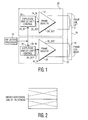
- a frame drive circuit 10 for a CRT device such as a CRT monitor or a CRT television set and the drive circuit 10 includes a deflection processor 14 and a frame coil 16.
- the frame drive circuit 10 includes a first core half 12 and a second core half 18 of the frame coil 16 and a first coil driver 20 and a second coil driver 22.
- the deflection processor 14 develops, as is well know, a deflection processor output signal.
- the deflection processor output signal is applied to each of the first driver 20 and the second driver 22.
- Each of the first driver 20 and the second driver 22 are selectively operative independently of each other to develop respectively a first coil drive signal and a second coil drive signal as a function of the deflection processor output signal.
- the first coil drive signal and the second coil drive signal are in turn applied to a respective one of the first coil half 12 and the second coil half 18.
- the two coil signals may differ in amplitude and one may be DC shifted relative to the other.
- the inventor has realized that applying different current to the two coils enables correcting the tilting of the picture without the need of an extra rotation coil used in some high-end CRT display system.
- the current difference enables correcting trapezoidal, rotational and parallelogram tilt of the picture.
- the adjustment of the respective coil currents may be effected at the time of manufacture of the display through testing or directly by the user during a tilt correction set up.
- each of the first driver 20 and the second driver 22 amplify the deflection processor output signal to develop each respective one of the first coil drive signal and the second coil drive signal.
- the amplification of the deflection processor output signal may be selected such that the resultant one of the first coil drive signal and the second coil drive signal when applied to the first coil half 12 and the second coil half 18, respectively, are operative to correct rotation of an image of the CRT monitor, as best seen in Fig.2 .
- the amplification of the deflection processor output signal by each of the first driver 20 and the second driver 22 may be substantially equal if the rotation of the CRT image is caused by a constant ambient field, such as the magnetic field of the earth. Furthermore, the ratio of the amplification of the deflection processor output signal may also be selectively adjusted to provide for trapezoidal correction, as best seen in Fig.4 .
- each of the first driver 20 and the second driver 22 further DC shift the deflection processor output signal to develop each respective one of the first coil drive signal and the second coil drive signal.
- the DC level shift of the deflection processor output signal may be selected such that the resultant one of the first coil drive signal and the second coil drive signal when applied to the first coil half 12 and the second coil half 18, respectively, are operative to parallelogram distortion of an image of the CRT monitor, as best seen in Fig.3 .
- the amplification of the deflection processor output signal may all be utilized, alone or in any combination, in practicing the present invention.
- a CRT image will exhibit several forms of distortion, and correction of such distortion is accomplished by separate user settings for each type of distortion, as in the prior art.
- the present invention allows for the simplified apparatus to correct for several types of distortion simultaneously.
- each of the first driver 20 and the second driver 22 include an amplifier 24, 26 having an input 24_IN, 26_IN and an output 24_OUT, 26_OUT.
- the input 24_IN, 26_IN of each amplifier 24, 26 is adapted to receive the deflection processor output signal.
- the output 24_OUT, 26_OUT of each amplifier 24, 26 develops an amplified signal for application to a respective one of the first coil half 12 and the second coil half 18.
- Each of the first driver 20 and the second driver 22 may further include a DC level shifter 28, 30 having respective inputs 28_IN, 30_IN and respective outputs 28_OUT, 30_OUT.
- the input 28_IN, 30_IN of each DC level shifter 28, 30 is adapted to receive the deflection processor output signal from the deflection processor 14.
- the output 28_OUT, 30_OUT of each DC level shifter 28, 30 develops a DC level shifted signal for application to a respective one of the first coil half 12 and the second coil half 18.
- the amplifier 24, 26 and the DC level shifter 28, 30 of each driver 20, 22 may be separate components connected in series or a single circuit, as seen in Fig. 1 , that provides both functions.
Landscapes
- Engineering & Computer Science (AREA)
- Multimedia (AREA)
- Signal Processing (AREA)
- Details Of Television Scanning (AREA)
Claims (9)
- Appareil à tube à rayons cathodiques comprenant :un processeur de déflexion (14) délivrant un signal de sortie de processeur de déflexion ; et un circuit de trame comprenant :une bobine de trame (16), la bobine de trame étant soit une bobine horizontale, soit une bobine verticale ;un premier excitateur (20) et un deuxième excitateur (22), ledit signal de sortie de processeur de déflexion étant appliqué à chacun dudit premier excitateur (20) et dudit deuxième excitateur (22), chacun dudit premier excitateur (20) et dudit deuxième excitateur (22) étant sélectivement exploitable indépendamment l'un de l'autre pour développer respectivement un premier signal d'excitation de bobine (24_OUT) et un deuxième signal d'excitation de bobine (26_OUT) en fonction dudit signal de sortie de processeur de déflexion,l'appareil étant caractérisé en ce que :ladite bobine de trame comprend une première moitié de noyau (12) et une deuxième moitié de noyau (18) ; etledit premier signal d'excitation de bobine (24_OUT) et ledit deuxième signal d'excitation de bobine (26_OUT) sont appliqués à une moitié de bobine respective parmi ladite première moitié de bobine (12) et ladite deuxième moitié de bobine (18) afin de corriger une distorsion d'image incluant une distorsion trapézoïdale, rotationnelle et parallélogrammique.
- L'appareil tel qu'exposé dans la revendication 1, où chacun dudit premier excitateur (20) et dudit deuxième excitateur (22) amplifie ledit signal de sortie de processeur de déflexion pour développer chaque signal respectif parmi ledit premier signal d'excitation de bobine (24_OUT) et ledit deuxième signal d'excitation de bobine (26_OUT).
- L'appareil tel qu'exposé dans la revendication 1, où chacun dudit premier excitateur (20) et dudit deuxième excitateur (22) décale en CC ledit signal de sortie de processeur de déflexion pour développer chaque signal respectif parmi ledit premier signal d'excitation de bobine (24_OUT) et ledit deuxième signal d'excitation de bobine (26_OUT).
- L'appareil tel qu'exposé dans la revendication 1, où chacun dudit premier excitateur (20) et dudit deuxième excitateur (22) inclut un amplificateur (24, 26) comprenant une entrée (24_IN, 26_IN) et une sortie (24_OUT, 26_OUT), ladite entrée (24_IN, 26_IN) de chaque amplificateur (24, 26) étant apte à recevoir ledit signal de sortie de processeur de déflexion, ladite sortie (24_OUT, 26_OUT) de chaque amplificateur (24, 26) développant un signal amplifié destiné à être appliqué à une moitié de bobine respective parmi ladite première moitié de bobine (12) et ladite deuxième moitié de bobine (18).
- L'appareil tel qu'exposé dans la revendication 1, où chacun dudit premier excitateur (20) et dudit deuxième excitateur (22) inclut un décaleur de niveau CC (28, 30) comprenant une entrée (28_IN, 30_IN) et une sortie (28_OUT, 30_OUT), ladite entrée (28_IN, 30_IN) de chaque décaleur de niveau CC (28, 30) étant apte à recevoir ledit signal de sortie de processeur de déflexion, ladite sortie (28_OUT, 30_OUT) de chaque décaleur de niveau CC (28, 30) développant un signal décalé en niveau CC destiné à être appliqué à une moitié de bobine respective parmi ladite première moitié de bobine (12) et ladite deuxième moitié de bobine (18).
- L'appareil de la revendication 1, où le circuit de trame est compris dans un circuit intégré.
- Procédé de correction de distorsion d'une image d'un écran à tube à rayons cathodiques comprenant un processeur de déflexion (14) et une bobine de trame (16) comportant les étapes consistant à :développer sélectivement, indépendamment l'un de l'autre, un premier signal d'excitation de bobine (24_OUT) et un deuxième signal d'excitation de bobine (26_OUT) en fonction d'un signal de sortie de processeur de déflexion développé par ledit processeur de déflexion ;le procédé étant caractérisé par :l'application dudit premier signal d'excitation de bobine (24_OUT) et dudit deuxième signal d'excitation de bobine (26_OUT) à une moitié de bobine respective parmi une première moitié de bobine (12) et une deuxième moitié de bobine (18) de ladite bobine de trame (16).
- Procédé tel qu'exposé dans la revendication 7, où ladite étape de développement inclut l'amplification dudit signal de sortie de processeur de déflexion pour développer chaque signal respectif parmi ledit premier signal d'excitation de bobine (24_OUT) et ledit deuxième signal d'excitation de bobine (26 OUT).
- Procédé tel qu'exposé dans la revendication 7, où ladite étape de développement inclut le décalage de niveau CC dudit signal de sortie de processeur de déflexion pour développer chaque signal respectif parmi ledit premier signal d'excitation de bobine (24_OUT) et ledit deuxième signal d'excitation de bobine (26_OUT).
Applications Claiming Priority (3)
| Application Number | Priority Date | Filing Date | Title |
|---|---|---|---|
| US43134402P | 2002-12-06 | 2002-12-06 | |
| US431344P | 2002-12-06 | ||
| PCT/IB2003/005606 WO2004054236A1 (fr) | 2002-12-06 | 2003-12-03 | Appareil de commande de deflexion de trames et procede associe |
Publications (3)
| Publication Number | Publication Date |
|---|---|
| EP1570646A1 EP1570646A1 (fr) | 2005-09-07 |
| EP1570646B1 true EP1570646B1 (fr) | 2012-10-24 |
| EP1570646B8 EP1570646B8 (fr) | 2012-12-19 |
Family
ID=32507715
Family Applications (1)
| Application Number | Title | Priority Date | Filing Date |
|---|---|---|---|
| EP03775660A Expired - Lifetime EP1570646B8 (fr) | 2002-12-06 | 2003-12-03 | Appareil de commande de deflexion de trames et procede associe |
Country Status (8)
| Country | Link |
|---|---|
| US (1) | US8362716B2 (fr) |
| EP (1) | EP1570646B8 (fr) |
| JP (1) | JP4409440B2 (fr) |
| KR (1) | KR20050088098A (fr) |
| CN (1) | CN100431334C (fr) |
| AU (1) | AU2003283679A1 (fr) |
| TW (1) | TW200501739A (fr) |
| WO (1) | WO2004054236A1 (fr) |
Citations (1)
| Publication number | Priority date | Publication date | Assignee | Title |
|---|---|---|---|---|
| DE4201700A1 (de) * | 1992-01-23 | 1993-07-29 | Thomson Brandt Gmbh | Schaltung zur korrektur der bildgeometrie in einem fernsehempfaenger |
Family Cites Families (14)
| Publication number | Priority date | Publication date | Assignee | Title |
|---|---|---|---|---|
| KR970009492B1 (ko) | 1994-05-19 | 1997-06-13 | 삼성전자 주식회사 | 수상관의 화상보정회로 및 그 방법 |
| US6013989A (en) * | 1996-05-20 | 2000-01-11 | Samsung Electronics Co., Ltd. | Wide-band horizontal linearity correction circuit |
| KR100195907B1 (ko) | 1996-08-27 | 1999-06-15 | 윤종용 | 화면의 기울기 보정회로 |
| CN1067198C (zh) * | 1996-11-07 | 2001-06-13 | 神达电脑股份有限公司 | 南北向梯形失真的补偿装置及方法 |
| KR100242839B1 (ko) * | 1997-04-14 | 2000-02-01 | 윤종용 | 디스플레이 모니터의 상조정 회로 |
| KR100242841B1 (ko) * | 1997-05-27 | 2000-02-01 | 윤종용 | 디스플레이 장치의 상하 왜곡 보정 회로 |
| KR100268150B1 (ko) * | 1997-05-29 | 2000-10-16 | 윤종용 | 복합 영상신호의 동기 신호 재생 회로 |
| KR100284483B1 (ko) | 1997-12-17 | 2001-03-15 | 이형도 | 편향 요크의 미스컨버전스 및 기하학적 왜곡 보정 장칙 |
| US6262779B1 (en) * | 1998-02-10 | 2001-07-17 | Hitachi, Ltd | Display apparatus with circuit expanding horizontal retrace interval of horizontal deflection current |
| US6369780B2 (en) * | 1999-09-30 | 2002-04-09 | Thomson Licensing S.A. | Auxiliary deflection winding driver disabling arrangement |
| KR100662573B1 (ko) * | 1999-12-23 | 2006-12-28 | 삼성전자주식회사 | 영상표시기기의 수평편향 보정회로 |
| JP2001210255A (ja) | 2000-01-28 | 2001-08-03 | Totoku Electric Co Ltd | モノクロ用偏向ヨーク |
| JP2002094829A (ja) * | 2000-09-12 | 2002-03-29 | Mitsubishi Electric Corp | 画面ノイズ除去装置及び陰極線管表示装置 |
| JP2007107503A (ja) | 2005-10-17 | 2007-04-26 | Nissan Diesel Motor Co Ltd | ピストンの冷却構造 |
-
2003
- 2003-12-03 AU AU2003283679A patent/AU2003283679A1/en not_active Abandoned
- 2003-12-03 CN CNB2003801049922A patent/CN100431334C/zh not_active Expired - Fee Related
- 2003-12-03 WO PCT/IB2003/005606 patent/WO2004054236A1/fr not_active Ceased
- 2003-12-03 US US10/537,673 patent/US8362716B2/en not_active Expired - Fee Related
- 2003-12-03 EP EP03775660A patent/EP1570646B8/fr not_active Expired - Lifetime
- 2003-12-03 TW TW092134028A patent/TW200501739A/zh unknown
- 2003-12-03 JP JP2004558939A patent/JP4409440B2/ja not_active Expired - Fee Related
- 2003-12-03 KR KR1020057010110A patent/KR20050088098A/ko not_active Withdrawn
Patent Citations (1)
| Publication number | Priority date | Publication date | Assignee | Title |
|---|---|---|---|---|
| DE4201700A1 (de) * | 1992-01-23 | 1993-07-29 | Thomson Brandt Gmbh | Schaltung zur korrektur der bildgeometrie in einem fernsehempfaenger |
Also Published As
| Publication number | Publication date |
|---|---|
| JP2006509462A (ja) | 2006-03-16 |
| TW200501739A (en) | 2005-01-01 |
| US8362716B2 (en) | 2013-01-29 |
| AU2003283679A1 (en) | 2004-06-30 |
| CN100431334C (zh) | 2008-11-05 |
| EP1570646A1 (fr) | 2005-09-07 |
| JP4409440B2 (ja) | 2010-02-03 |
| CN1720714A (zh) | 2006-01-11 |
| EP1570646B8 (fr) | 2012-12-19 |
| WO2004054236A1 (fr) | 2004-06-24 |
| KR20050088098A (ko) | 2005-09-01 |
| US20110007038A1 (en) | 2011-01-13 |
Similar Documents
| Publication | Publication Date | Title |
|---|---|---|
| EP0151039B2 (fr) | Dispositif pour l'amélioration de contarste vidéo | |
| EP1570646B1 (fr) | Appareil de commande de deflexion de trames et procede associe | |
| KR19990016555A (ko) | 텔레비전 화면의 부분확대 제어장치 | |
| US5416818A (en) | X-ray TV camera having function to switch a visual field of X-ray image | |
| US6377317B1 (en) | Method and apparatus for correcting color component focusing in a rear-projection television set | |
| US5936363A (en) | User controlled deflection apparatus for correcting upper and lower distortions of a CRT | |
| EP1445943A1 (fr) | Unite de commande d'amplitude verticale/horizontale | |
| KR100265167B1 (ko) | 디스플레이 장치의 휘도 편차 보정 장치 | |
| KR19990026700A (ko) | 영상화면의 확대 장치와 방법 | |
| US6570625B1 (en) | Display apparatus and display method | |
| JPH10322714A (ja) | 陰極管内の電子ビーム偏向用の装置 | |
| KR100265168B1 (ko) | 디스플레이 장치의 휘도 편차 보정 장치 | |
| KR100601629B1 (ko) | 고압보정장치 | |
| JP3740337B2 (ja) | Crtを用いた表示装置及びそのフォーカス制御装置 | |
| JP3316282B2 (ja) | テレビジョン受像機 | |
| KR100275008B1 (ko) | 디스플레이 장치의 사다리꼴 국부 왜곡 보정 장치 및 방법 | |
| JPH06261219A (ja) | ディスプレイモニタ | |
| KR100257256B1 (ko) | 텔레비젼의 핀쿠션 보정장치 | |
| KR100263092B1 (ko) | 디스플레이 장치의 휘도 편차 보정 장치 | |
| EP1523197A2 (fr) | Appareil et méthode d'ajustage de convergence d'un téléviseur à projection | |
| US6522091B1 (en) | Circuit and method that allows the amplitudes of vertical correction signal components to be adjusted independently | |
| KR0154653B1 (ko) | 와이드 텔레비전의 화면크기 자동절환장치 | |
| JP3077159B2 (ja) | ダイナミックフォーカス回路 | |
| JPS60160268A (ja) | カラ−ビデオ画質調整装置 | |
| EP1565005A1 (fr) | Dispositif de commande de convergence pour un dispositif d'affichage vidéo |
Legal Events
| Date | Code | Title | Description |
|---|---|---|---|
| PUAI | Public reference made under article 153(3) epc to a published international application that has entered the european phase |
Free format text: ORIGINAL CODE: 0009012 |
|
| 17P | Request for examination filed |
Effective date: 20050706 |
|
| AK | Designated contracting states |
Kind code of ref document: A1 Designated state(s): AT BE BG CH CY CZ DE DK EE ES FI FR GB GR HU IE IT LI LU MC NL PT RO SE SI SK TR |
|
| AX | Request for extension of the european patent |
Extension state: AL LT LV MK |
|
| DAX | Request for extension of the european patent (deleted) | ||
| RAP1 | Party data changed (applicant data changed or rights of an application transferred) |
Owner name: NXP B.V. |
|
| 17Q | First examination report despatched |
Effective date: 20090626 |
|
| RAP1 | Party data changed (applicant data changed or rights of an application transferred) |
Owner name: TRIDENT MICROSYSTEMS (FAR EAST) LTD. |
|
| GRAP | Despatch of communication of intention to grant a patent |
Free format text: ORIGINAL CODE: EPIDOSNIGR1 |
|
| GRAS | Grant fee paid |
Free format text: ORIGINAL CODE: EPIDOSNIGR3 |
|
| GRAA | (expected) grant |
Free format text: ORIGINAL CODE: 0009210 |
|
| AK | Designated contracting states |
Kind code of ref document: B1 Designated state(s): AT BE BG CH CY CZ DE DK EE ES FI FR GB GR HU IE IT LI LU MC NL PT RO SE SI SK TR |
|
| REG | Reference to a national code |
Ref country code: GB Ref legal event code: FG4D |
|
| REG | Reference to a national code |
Ref country code: CH Ref legal event code: EP |
|
| REG | Reference to a national code |
Ref country code: AT Ref legal event code: REF Ref document number: 581433 Country of ref document: AT Kind code of ref document: T Effective date: 20121115 |
|
| REG | Reference to a national code |
Ref country code: IE Ref legal event code: FG4D |
|
| RAP2 | Party data changed (patent owner data changed or rights of a patent transferred) |
Owner name: ENTROPIC COMMUNICATIONS, INC. |
|
| REG | Reference to a national code |
Ref country code: DE Ref legal event code: R096 Ref document number: 60342440 Country of ref document: DE Effective date: 20121220 |
|
| REG | Reference to a national code |
Ref country code: AT Ref legal event code: MK05 Ref document number: 581433 Country of ref document: AT Kind code of ref document: T Effective date: 20121024 |
|
| REG | Reference to a national code |
Ref country code: NL Ref legal event code: VDEP Effective date: 20121024 |
|
| PG25 | Lapsed in a contracting state [announced via postgrant information from national office to epo] |
Ref country code: NL Free format text: LAPSE BECAUSE OF FAILURE TO SUBMIT A TRANSLATION OF THE DESCRIPTION OR TO PAY THE FEE WITHIN THE PRESCRIBED TIME-LIMIT Effective date: 20121024 Ref country code: SE Free format text: LAPSE BECAUSE OF FAILURE TO SUBMIT A TRANSLATION OF THE DESCRIPTION OR TO PAY THE FEE WITHIN THE PRESCRIBED TIME-LIMIT Effective date: 20121024 Ref country code: FI Free format text: LAPSE BECAUSE OF FAILURE TO SUBMIT A TRANSLATION OF THE DESCRIPTION OR TO PAY THE FEE WITHIN THE PRESCRIBED TIME-LIMIT Effective date: 20121024 Ref country code: ES Free format text: LAPSE BECAUSE OF FAILURE TO SUBMIT A TRANSLATION OF THE DESCRIPTION OR TO PAY THE FEE WITHIN THE PRESCRIBED TIME-LIMIT Effective date: 20130204 |
|
| PG25 | Lapsed in a contracting state [announced via postgrant information from national office to epo] |
Ref country code: GR Free format text: LAPSE BECAUSE OF FAILURE TO SUBMIT A TRANSLATION OF THE DESCRIPTION OR TO PAY THE FEE WITHIN THE PRESCRIBED TIME-LIMIT Effective date: 20130125 Ref country code: CY Free format text: LAPSE BECAUSE OF FAILURE TO SUBMIT A TRANSLATION OF THE DESCRIPTION OR TO PAY THE FEE WITHIN THE PRESCRIBED TIME-LIMIT Effective date: 20121024 Ref country code: BE Free format text: LAPSE BECAUSE OF FAILURE TO SUBMIT A TRANSLATION OF THE DESCRIPTION OR TO PAY THE FEE WITHIN THE PRESCRIBED TIME-LIMIT Effective date: 20121024 Ref country code: SI Free format text: LAPSE BECAUSE OF FAILURE TO SUBMIT A TRANSLATION OF THE DESCRIPTION OR TO PAY THE FEE WITHIN THE PRESCRIBED TIME-LIMIT Effective date: 20121024 Ref country code: PT Free format text: LAPSE BECAUSE OF FAILURE TO SUBMIT A TRANSLATION OF THE DESCRIPTION OR TO PAY THE FEE WITHIN THE PRESCRIBED TIME-LIMIT Effective date: 20130225 |
|
| PG25 | Lapsed in a contracting state [announced via postgrant information from national office to epo] |
Ref country code: AT Free format text: LAPSE BECAUSE OF FAILURE TO SUBMIT A TRANSLATION OF THE DESCRIPTION OR TO PAY THE FEE WITHIN THE PRESCRIBED TIME-LIMIT Effective date: 20121024 |
|
| PG25 | Lapsed in a contracting state [announced via postgrant information from national office to epo] |
Ref country code: DK Free format text: LAPSE BECAUSE OF FAILURE TO SUBMIT A TRANSLATION OF THE DESCRIPTION OR TO PAY THE FEE WITHIN THE PRESCRIBED TIME-LIMIT Effective date: 20121024 Ref country code: CZ Free format text: LAPSE BECAUSE OF FAILURE TO SUBMIT A TRANSLATION OF THE DESCRIPTION OR TO PAY THE FEE WITHIN THE PRESCRIBED TIME-LIMIT Effective date: 20121024 Ref country code: MC Free format text: LAPSE BECAUSE OF NON-PAYMENT OF DUE FEES Effective date: 20121231 Ref country code: SK Free format text: LAPSE BECAUSE OF FAILURE TO SUBMIT A TRANSLATION OF THE DESCRIPTION OR TO PAY THE FEE WITHIN THE PRESCRIBED TIME-LIMIT Effective date: 20121024 Ref country code: EE Free format text: LAPSE BECAUSE OF FAILURE TO SUBMIT A TRANSLATION OF THE DESCRIPTION OR TO PAY THE FEE WITHIN THE PRESCRIBED TIME-LIMIT Effective date: 20121024 Ref country code: BG Free format text: LAPSE BECAUSE OF FAILURE TO SUBMIT A TRANSLATION OF THE DESCRIPTION OR TO PAY THE FEE WITHIN THE PRESCRIBED TIME-LIMIT Effective date: 20130124 |
|
| REG | Reference to a national code |
Ref country code: CH Ref legal event code: PL |
|
| PG25 | Lapsed in a contracting state [announced via postgrant information from national office to epo] |
Ref country code: RO Free format text: LAPSE BECAUSE OF FAILURE TO SUBMIT A TRANSLATION OF THE DESCRIPTION OR TO PAY THE FEE WITHIN THE PRESCRIBED TIME-LIMIT Effective date: 20121024 Ref country code: IT Free format text: LAPSE BECAUSE OF FAILURE TO SUBMIT A TRANSLATION OF THE DESCRIPTION OR TO PAY THE FEE WITHIN THE PRESCRIBED TIME-LIMIT Effective date: 20121024 |
|
| PLBE | No opposition filed within time limit |
Free format text: ORIGINAL CODE: 0009261 |
|
| STAA | Information on the status of an ep patent application or granted ep patent |
Free format text: STATUS: NO OPPOSITION FILED WITHIN TIME LIMIT |
|
| 26N | No opposition filed |
Effective date: 20130725 |
|
| PG25 | Lapsed in a contracting state [announced via postgrant information from national office to epo] |
Ref country code: LI Free format text: LAPSE BECAUSE OF NON-PAYMENT OF DUE FEES Effective date: 20121231 Ref country code: CH Free format text: LAPSE BECAUSE OF NON-PAYMENT OF DUE FEES Effective date: 20121231 |
|
| REG | Reference to a national code |
Ref country code: DE Ref legal event code: R097 Ref document number: 60342440 Country of ref document: DE Effective date: 20130725 |
|
| PG25 | Lapsed in a contracting state [announced via postgrant information from national office to epo] |
Ref country code: TR Free format text: LAPSE BECAUSE OF FAILURE TO SUBMIT A TRANSLATION OF THE DESCRIPTION OR TO PAY THE FEE WITHIN THE PRESCRIBED TIME-LIMIT Effective date: 20121024 |
|
| PG25 | Lapsed in a contracting state [announced via postgrant information from national office to epo] |
Ref country code: LU Free format text: LAPSE BECAUSE OF NON-PAYMENT OF DUE FEES Effective date: 20121203 |
|
| PG25 | Lapsed in a contracting state [announced via postgrant information from national office to epo] |
Ref country code: HU Free format text: LAPSE BECAUSE OF FAILURE TO SUBMIT A TRANSLATION OF THE DESCRIPTION OR TO PAY THE FEE WITHIN THE PRESCRIBED TIME-LIMIT Effective date: 20031203 |
|
| PGFP | Annual fee paid to national office [announced via postgrant information from national office to epo] |
Ref country code: GB Payment date: 20141229 Year of fee payment: 12 Ref country code: IE Payment date: 20141229 Year of fee payment: 12 |
|
| PGFP | Annual fee paid to national office [announced via postgrant information from national office to epo] |
Ref country code: FR Payment date: 20141217 Year of fee payment: 12 |
|
| PGFP | Annual fee paid to national office [announced via postgrant information from national office to epo] |
Ref country code: DE Payment date: 20151229 Year of fee payment: 13 |
|
| GBPC | Gb: european patent ceased through non-payment of renewal fee |
Effective date: 20151203 |
|
| REG | Reference to a national code |
Ref country code: IE Ref legal event code: MM4A |
|
| REG | Reference to a national code |
Ref country code: FR Ref legal event code: ST Effective date: 20160831 |
|
| PG25 | Lapsed in a contracting state [announced via postgrant information from national office to epo] |
Ref country code: IE Free format text: LAPSE BECAUSE OF NON-PAYMENT OF DUE FEES Effective date: 20151203 Ref country code: GB Free format text: LAPSE BECAUSE OF NON-PAYMENT OF DUE FEES Effective date: 20151203 |
|
| PG25 | Lapsed in a contracting state [announced via postgrant information from national office to epo] |
Ref country code: FR Free format text: LAPSE BECAUSE OF NON-PAYMENT OF DUE FEES Effective date: 20151231 |
|
| REG | Reference to a national code |
Ref country code: DE Ref legal event code: R119 Ref document number: 60342440 Country of ref document: DE |
|
| PG25 | Lapsed in a contracting state [announced via postgrant information from national office to epo] |
Ref country code: DE Free format text: LAPSE BECAUSE OF NON-PAYMENT OF DUE FEES Effective date: 20170701 |