EP1568948A2 - Koaxial-Feststoffgranulat Heizanlage für automatischenBetrieb und Reinigung von Kessel und Rondellbrenner - Google Patents
Koaxial-Feststoffgranulat Heizanlage für automatischenBetrieb und Reinigung von Kessel und Rondellbrenner Download PDFInfo
- Publication number
- EP1568948A2 EP1568948A2 EP05003626A EP05003626A EP1568948A2 EP 1568948 A2 EP1568948 A2 EP 1568948A2 EP 05003626 A EP05003626 A EP 05003626A EP 05003626 A EP05003626 A EP 05003626A EP 1568948 A2 EP1568948 A2 EP 1568948A2
- Authority
- EP
- European Patent Office
- Prior art keywords
- burner
- boiler
- exhaust gas
- cleaning
- heating system
- Prior art date
- Legal status (The legal status is an assumption and is not a legal conclusion. Google has not performed a legal analysis and makes no representation as to the accuracy of the status listed.)
- Withdrawn
Links
Images


Classifications
-
- F—MECHANICAL ENGINEERING; LIGHTING; HEATING; WEAPONS; BLASTING
- F24—HEATING; RANGES; VENTILATING
- F24H—FLUID HEATERS, e.g. WATER OR AIR HEATERS, HAVING HEAT-GENERATING MEANS, e.g. HEAT PUMPS, IN GENERAL
- F24H1/00—Water heaters, e.g. boilers, continuous-flow heaters or water-storage heaters
- F24H1/22—Water heaters other than continuous-flow or water-storage heaters, e.g. water heaters for central heating
- F24H1/24—Water heaters other than continuous-flow or water-storage heaters, e.g. water heaters for central heating with water mantle surrounding the combustion chamber or chambers
- F24H1/26—Water heaters other than continuous-flow or water-storage heaters, e.g. water heaters for central heating with water mantle surrounding the combustion chamber or chambers the water mantle forming an integral body
- F24H1/28—Water heaters other than continuous-flow or water-storage heaters, e.g. water heaters for central heating with water mantle surrounding the combustion chamber or chambers the water mantle forming an integral body including one or more furnace or fire tubes
- F24H1/285—Water heaters other than continuous-flow or water-storage heaters, e.g. water heaters for central heating with water mantle surrounding the combustion chamber or chambers the water mantle forming an integral body including one or more furnace or fire tubes with the fire tubes arranged alongside the combustion chamber
-
- F—MECHANICAL ENGINEERING; LIGHTING; HEATING; WEAPONS; BLASTING
- F23—COMBUSTION APPARATUS; COMBUSTION PROCESSES
- F23B—METHODS OR APPARATUS FOR COMBUSTION USING ONLY SOLID FUEL
- F23B1/00—Combustion apparatus using only lump fuel
- F23B1/16—Combustion apparatus using only lump fuel the combustion apparatus being modified according to the form of grate or other fuel support
- F23B1/26—Combustion apparatus using only lump fuel the combustion apparatus being modified according to the form of grate or other fuel support using imperforate fuel supports
-
- F—MECHANICAL ENGINEERING; LIGHTING; HEATING; WEAPONS; BLASTING
- F23—COMBUSTION APPARATUS; COMBUSTION PROCESSES
- F23B—METHODS OR APPARATUS FOR COMBUSTION USING ONLY SOLID FUEL
- F23B7/00—Combustion techniques; Other solid-fuel combustion apparatus
- F23B7/002—Combustion techniques; Other solid-fuel combustion apparatus characterised by gas flow arrangements
- F23B7/005—Combustion techniques; Other solid-fuel combustion apparatus characterised by gas flow arrangements with downdraught through fuel bed and grate
-
- F—MECHANICAL ENGINEERING; LIGHTING; HEATING; WEAPONS; BLASTING
- F23—COMBUSTION APPARATUS; COMBUSTION PROCESSES
- F23J—REMOVAL OR TREATMENT OF COMBUSTION PRODUCTS OR COMBUSTION RESIDUES; FLUES
- F23J1/00—Removing ash, clinker, or slag from combustion chambers
- F23J1/06—Mechanically-operated devices, e.g. clinker pushers
-
- F—MECHANICAL ENGINEERING; LIGHTING; HEATING; WEAPONS; BLASTING
- F24—HEATING; RANGES; VENTILATING
- F24H—FLUID HEATERS, e.g. WATER OR AIR HEATERS, HAVING HEAT-GENERATING MEANS, e.g. HEAT PUMPS, IN GENERAL
- F24H1/00—Water heaters, e.g. boilers, continuous-flow heaters or water-storage heaters
- F24H1/22—Water heaters other than continuous-flow or water-storage heaters, e.g. water heaters for central heating
- F24H1/24—Water heaters other than continuous-flow or water-storage heaters, e.g. water heaters for central heating with water mantle surrounding the combustion chamber or chambers
- F24H1/26—Water heaters other than continuous-flow or water-storage heaters, e.g. water heaters for central heating with water mantle surrounding the combustion chamber or chambers the water mantle forming an integral body
-
- F—MECHANICAL ENGINEERING; LIGHTING; HEATING; WEAPONS; BLASTING
- F24—HEATING; RANGES; VENTILATING
- F24H—FLUID HEATERS, e.g. WATER OR AIR HEATERS, HAVING HEAT-GENERATING MEANS, e.g. HEAT PUMPS, IN GENERAL
- F24H9/00—Details
- F24H9/0005—Details for water heaters
- F24H9/0042—Cleaning arrangements
Definitions
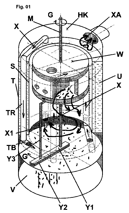
- the boiler “rondo” as well as the burner “rondell” essentially of cylindrical components, which are arranged coaxially. This allows inlet and outlet openings, as well as cleaning operations of one or more central, coaxial drive or control shafts (M) to operate.
- M central, coaxial drive or control shafts
- Containment space for incineration residues V
- boiler bottom plate with one or more bottom slots Y2
- scrapers Y1
- the burner (W) which closes at the top to the inner boiler cylinder and a non-illustrated upper cover over the upper exhaust gas collecting chamber with the outer boiler cylinder (T) , closes.
- the solid fuel for example pellets
- the solid fuel is burned “rondell” in the burner as in 1. and 2. and enters as exhaust gas flow in the inner boiler cylinder, which as a cyclone dust collector is working.
- the "dusty" dust component in the exhaust gas stream trickles down to the bottom of the boiler.
- the exhaust gas flow reaches a residual heat exchanger pipe (TR) consisting of only one exhaust pipe and consisting of vertical pipes in the boiler water. It arises from the fact that the individual vertical pipes are connected at the top and bottom by arches to a pipe course.
- TR residual heat exchanger pipe
- rotatable "scraper bars” On the bottom of the boiler cylinder is one or more rotatable "scraper bars" (Y1) , which are at rest, ie during the combustion process, above the floor slit (s) (Y2) .
- the "scraper (s)" (Y1) are rotated in the direction of arrow (G) before burner starts (similar to 3.6 described above), thus the combustion residues are stripped from the ground and glide in the circumferential direction of the bottom slots or ( Y2 ) until they finally fall out and land in the collection room (V) .
- the cleaning of the inner boiler cylinder surface ( S ) takes over the wiper strip ( Y3 ).
- a special feature is that the coaxial design of the drive centrally of one or more drive shaft (s) ( M ) is circular.
- the drive shaft ( M ) of the burner is extended to the bottom.
- the Antiebs variant is, as under 2.6. and 3.6. mentioned, irrelevant, because different Drive variants are possible and state of the art (gear motor, chain or Gear drive).
Landscapes
- Engineering & Computer Science (AREA)
- Mechanical Engineering (AREA)
- General Engineering & Computer Science (AREA)
- Physics & Mathematics (AREA)
- Chemical & Material Sciences (AREA)
- Combustion & Propulsion (AREA)
- Thermal Sciences (AREA)
- Cleaning In General (AREA)
- Gas Burners (AREA)
Abstract
Description
Zur Ergänzung wird erwähnt, dass bei dem Prototypbrenner (Fig.07) eine Brennerdüse (N) angeformt wurde, damit der Brenner an den Brennerflansch des Versuchskessels angebaut werden kann. Zwischen dem "Diskus"-Rost (B) und dem Boden der Brennerdüse (N) bleibt ein Schlitz (SL), durch welchen die Verbrennungsreste (H) nach unten in eine Auffwangwanne des Brennergehäuses fallen.
Bei dem Prototyp wird dazu die Antriebswelle (M), an deren unterem Ende die "Räumleiste" (Q) befestigt ist, über einen Kettenantrieb getrieben. Die Antiebsvariante (Stand der Technik) ist auch hier unerheblich, da auch andere Antriebsvarianten möglich sind. Nach dem Reinigungsvorgang verschließt die Räumleiste im Ruhezstand den Bodenschlitz.
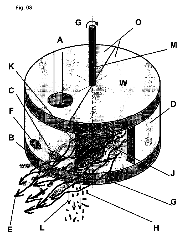
| A | Brennstoffzufuhr | Q | Drehbare Räumleiste |
| B | "Diskus"-Rost | R | Bodenschlitz |
| C | Zündeinrichtung | S | innerer Kesselzylinder |
| D | Brennerzylinder | T | äußerer Kesselzylinder |
| E | Abgasaustritt | TB | Verbindungsbogen, Abgasrohr |
| F | Verbrennungsluftzufuhr | TR | senkrechte Abgas Teilrohrstrecke |
| G | Drehrichtung | U | Heizwasser |
| H | Abgestreifte Verbrennungsreste | V | Ascheauffangraum |
| HK | Heizkessel | W | Brenner "rondell" |
| J | Abstreifkante | X | Abgasweg |
| K | Abgleitrichtung | X1 | unterer Abgaseintritt |
| L | Ausfallrichtung (unten) | XA | Abgasaustritt Kessel |
| M | Antriebs-, Steuerwelle | Y1 | Räumleiste Kessel |
| N | angeformte Brennerdüse, Testvariante | Y2 | Bodenschlitz Kessel |
| O | Brennerdeckel | Y3 | Abstreifleiste Kesselwandle |
| P | Bodenrost + Brennerzylinder | ||
| Fig.04,Fig.06, Brennervariante "B" |
Claims (10)
- Koaxial-Feststoffgranulat Heizanlage für automatischen Betrieb und Reinigung von Kessel und Rondellbrenner
dadurch gekennzeichnet, dass Heizbrenner W und Heizkessel HK um die eine mittlere Welle M konzentrisch angeordnet sind. - Heizanlage nach Patentanspruch 1
dadurch gekennzeichnet, dass eine konzentrische Welle M die Reinigungsvorgänge in Umfangsrichtung antreibt. - Heizanlage nach Patentanspruch 1
dadurch gekennzeichnet, dass eine konzentrische Welle M, als Steuerwelle die Funktionsabläufe in Umfangsrichtung übernimmt. - Heizanlage nach Patentanspruch 1
dadurch gekennzeichnet, dass die Reinigung der Kesselwand S über eine oder mehrere Abstreifleisten Y3 oder Abstreifbürsten Y3 um eine zentrische Welle M erfolgt. - Heizanlage nach Patentanspruch 1
dadurch gekennzeichnet, dass die Reinigung des Kesselbodens über eine oder mehrere Räumleisten Y1 um eine zentrische Welle M erfolgt.
Die Verbrennungsreste H können dann durch einen oder mehrere Bodenschlitze Y2 in den Ascheauffangraum V herausfallen. - Heizanlage nach Patentanspruch 1
dadurch gekennzeichnet, dass die Flammenführung im Rondellbrenner W tangential in Drehrichtung G horizontal um eine zentrische Welle M erfolgt und nach Umlauf radial austritt E. - Heizanlage nach Patentanspruch 1
dadurch gekennzeichnet, dass die Reinigung des drehbaren "Diskus" Rosts B des Rondellbrenners W durch Drehung um eine zentrische Welle M und abstreifen über eine Abstreifvorrichtung (Kante) J erfolgt, bis die Verbrennungsrückstände H nach unten fallen L. (Fig. 03 und Fig. 05) - Heizanlage nach Patentanspruch 1
dadurch gekennzeichnet, dass alternativ zu Schutzanspruch 7. die Reinigung des festen "Diskus" Rosts P des Rondellbrenners W durch Drehung einer Räumleiste Q um eine zentrische Welle M erfolgt und die Verbrennungsreste durch einen Bodenschlitz R nach unten herausfallen. (Fig. 04 und Fig. 06) - Heizanlage nach Patentanspruch 1
dadurch gekennzeichnet, dass die Abgasgeschwindigkeit vielfach erhöht wird, indem der Abgasstrom über den Abgaseintritt X1 bis zum Abgasaustritt XA nur einem einzigen Rohrverlauf folgend geführt wird. Die senkrecht im Kesselzylinder durch das Heizwasser U parallel verlaufenden Tauscherrohre TR sind dazu durch Abgasbögen TB in Reihe verbunden. - Heizanlage nach Patentanspruch 1
dadurch gekennzeichnet, dass die Abgasgeschwindigkeit vielfach erhöht wird, indem der Abgasstrom nur einem einzigen Rohrverlauf folgend von X1 bis XA - alternativ zu Schutzanspruch 9. - , schraubenförmig, konzentrisch, von unten nach oben steigend, im Kesselzylinder durch das Heizwasser U. (Fig. 02), geführt wird.
Applications Claiming Priority (2)
| Application Number | Priority Date | Filing Date | Title |
|---|---|---|---|
| DE202004002911U | 2004-02-25 | ||
| DE202004002911U DE202004002911U1 (de) | 2004-02-23 | 2004-02-25 | Koaxial-Feststoffgranulat-Heizanlage für automatischen Betrieb und Reinigung von Kessel und Rondellbrenner |
Publications (2)
| Publication Number | Publication Date |
|---|---|
| EP1568948A2 true EP1568948A2 (de) | 2005-08-31 |
| EP1568948A3 EP1568948A3 (de) | 2006-06-07 |
Family
ID=34745541
Family Applications (1)
| Application Number | Title | Priority Date | Filing Date |
|---|---|---|---|
| EP05003626A Withdrawn EP1568948A3 (de) | 2004-02-25 | 2005-02-20 | Koaxial-Feststoffgranulat Heizanlage für automatischenBetrieb und Reinigung von Kessel und Rondellbrenner |
Country Status (1)
| Country | Link |
|---|---|
| EP (1) | EP1568948A3 (de) |
Cited By (4)
| Publication number | Priority date | Publication date | Assignee | Title |
|---|---|---|---|---|
| US20150122241A1 (en) * | 2012-05-08 | 2015-05-07 | Stephen William John Grant | Wood pellet burner assembly |
| ITUA20162817A1 (it) * | 2016-04-22 | 2017-10-22 | De Longhi Appliances Srl | Caldaia |
| CN112066379A (zh) * | 2020-08-31 | 2020-12-11 | 姜爱涛 | 一种可自动清洁内壁的垃圾焚烧锅炉 |
| CN118089427A (zh) * | 2024-04-28 | 2024-05-28 | 陕西大力神航空新材料科技股份有限公司 | 一种真空自耗电弧炉的炉膛清理装置 |
Family Cites Families (5)
| Publication number | Priority date | Publication date | Assignee | Title |
|---|---|---|---|---|
| DE430239C (de) * | 1924-10-31 | 1926-06-12 | Richard Mews | Warmwasserheizungskessel |
| BE756970A (fr) * | 1969-10-02 | 1971-03-16 | Atomenergi Ab | Perfectionnements aux incinerateurs notamment d'ordures |
| GB2079910B (en) * | 1980-07-08 | 1983-11-09 | Dalby Harry Robert | Solid fuel burner |
| SE454112B (sv) * | 1984-07-26 | 1988-03-28 | Whole Crop Biotechnics Bv | Askutmatningsanordning |
| US4836115A (en) * | 1988-06-23 | 1989-06-06 | Macarthur Charles E | Vertical furnace |
-
2005
- 2005-02-20 EP EP05003626A patent/EP1568948A3/de not_active Withdrawn
Cited By (8)
| Publication number | Priority date | Publication date | Assignee | Title |
|---|---|---|---|---|
| US20150122241A1 (en) * | 2012-05-08 | 2015-05-07 | Stephen William John Grant | Wood pellet burner assembly |
| US10077904B2 (en) * | 2012-05-08 | 2018-09-18 | Stephen William John Grant | Wood pellet burner assembly |
| ITUA20162817A1 (it) * | 2016-04-22 | 2017-10-22 | De Longhi Appliances Srl | Caldaia |
| WO2017182664A1 (en) * | 2016-04-22 | 2017-10-26 | De' Longhi Appliances S.R.L. Con Unico Socio | Boiler |
| CN109416195A (zh) * | 2016-04-22 | 2019-03-01 | 德隆奇电器单股东有限责任公司 | 烧水器 |
| CN109416195B (zh) * | 2016-04-22 | 2021-06-15 | 德隆奇电器单一股东有限责任公司 | 烧水器 |
| CN112066379A (zh) * | 2020-08-31 | 2020-12-11 | 姜爱涛 | 一种可自动清洁内壁的垃圾焚烧锅炉 |
| CN118089427A (zh) * | 2024-04-28 | 2024-05-28 | 陕西大力神航空新材料科技股份有限公司 | 一种真空自耗电弧炉的炉膛清理装置 |
Also Published As
| Publication number | Publication date |
|---|---|
| EP1568948A3 (de) | 2006-06-07 |
Similar Documents
| Publication | Publication Date | Title |
|---|---|---|
| EP4056900B1 (de) | Biomasse-heizanlage mit einer verbesserten reinigungseinrichtung | |
| EP3789676A1 (de) | Drehrost mit einer reinigungseinrichtung für eine biomasse-heizanlage | |
| DD156840A5 (de) | Heizanlage | |
| DE3644030A1 (de) | Aufgeladener, kohlebefeuerter dampferzeuger | |
| DE2445057A1 (de) | Muellverbrennungsofen | |
| DE69012651T2 (de) | Verfahren und Vorrichtung zur Verbrennung von brennbarem, festem Rückstand einer chemischen Anlage. | |
| DE19528422C1 (de) | Abfallverbrennungsofen | |
| EP1695009A1 (de) | Vergaserheizkessel für feste brennstoffe, insbesondere für strohballen, mit optimierten abgaswerten | |
| DE19828767A1 (de) | Heizkessel für die Verbrennung von festem Brennstoff | |
| DE202004002911U1 (de) | Koaxial-Feststoffgranulat-Heizanlage für automatischen Betrieb und Reinigung von Kessel und Rondellbrenner | |
| EP2116790B1 (de) | Feuerungseinrichtung mit einer Reinigungseinrichtung | |
| CN112066361A (zh) | 湿法除尘式节能燃煤锅炉 | |
| EP1568948A3 (de) | Koaxial-Feststoffgranulat Heizanlage für automatischenBetrieb und Reinigung von Kessel und Rondellbrenner | |
| DE19743338A1 (de) | Feuerungsanlage | |
| DE3703855C2 (de) | ||
| DE2148065A1 (de) | Heizkessel fur industrielle Anlagen | |
| DE926978C (de) | Gaserzeuger | |
| DE10324058B4 (de) | Wärmetauscher sowie Heizkraftanlage | |
| EP4483096B1 (de) | Vorrichtung zur behandlung von abgasen einer kleinfeuerungsanlage | |
| DE2525745C2 (de) | Schmelzkammerfeuerung mit Flugasche-Rückführung | |
| DE2638105A1 (de) | Abfallverbrennungseinrichtung | |
| DE678140C (de) | Kohlenstaubfeuerung | |
| DE202009007254U1 (de) | Vorrichtung | |
| AT509471B1 (de) | Ofen, welcher einen brennraum und einen darunter befindlichen ascheraum aufweist | |
| DE2543216A1 (de) | Anlage zur reinigung staubbeladener abgase |
Legal Events
| Date | Code | Title | Description |
|---|---|---|---|
| PUAI | Public reference made under article 153(3) epc to a published international application that has entered the european phase |
Free format text: ORIGINAL CODE: 0009012 |
|
| AK | Designated contracting states |
Kind code of ref document: A2 Designated state(s): AT BE BG CH CY CZ DE DK EE ES FI FR GB GR HU IE IS IT LI LT LU MC NL PL PT RO SE SI SK TR |
|
| AX | Request for extension of the european patent |
Extension state: AL BA HR LV MK YU |
|
| PUAL | Search report despatched |
Free format text: ORIGINAL CODE: 0009013 |
|
| AK | Designated contracting states |
Kind code of ref document: A3 Designated state(s): AT BE BG CH CY CZ DE DK EE ES FI FR GB GR HU IE IS IT LI LT LU MC NL PL PT RO SE SI SK TR |
|
| AX | Request for extension of the european patent |
Extension state: AL BA HR LV MK YU |
|
| AKX | Designation fees paid | ||
| STAA | Information on the status of an ep patent application or granted ep patent |
Free format text: STATUS: THE APPLICATION IS DEEMED TO BE WITHDRAWN |
|
| 18D | Application deemed to be withdrawn |
Effective date: 20061208 |
|
| REG | Reference to a national code |
Ref country code: DE Ref legal event code: 8566 |