EP1568804A2 - Balloneinengungshülsen für Textilmaschinen - Google Patents
Balloneinengungshülsen für Textilmaschinen Download PDFInfo
- Publication number
- EP1568804A2 EP1568804A2 EP05000359A EP05000359A EP1568804A2 EP 1568804 A2 EP1568804 A2 EP 1568804A2 EP 05000359 A EP05000359 A EP 05000359A EP 05000359 A EP05000359 A EP 05000359A EP 1568804 A2 EP1568804 A2 EP 1568804A2
- Authority
- EP
- European Patent Office
- Prior art keywords
- balloon
- sleeve
- head part
- bearing
- narrowing
- Prior art date
- Legal status (The legal status is an assumption and is not a legal conclusion. Google has not performed a legal analysis and makes no representation as to the accuracy of the status listed.)
- Withdrawn
Links
Images

Classifications
-
- D—TEXTILES; PAPER
- D01—NATURAL OR MAN-MADE THREADS OR FIBRES; SPINNING
- D01H—SPINNING OR TWISTING
- D01H7/00—Spinning or twisting arrangements
- D01H7/02—Spinning or twisting arrangements for imparting permanent twist
- D01H7/66—Cap arrangements
- D01H7/68—Cap constructions
Definitions
- the present invention relates to balloon constricting sleeves for a Textile machine, preferably a spinning machine or twisting machine, according to the characterizing part of the independent claim.
- the bearing in particular a head bearing, is preferably made of robust, heat-, abrasion- and stress-resistant material, whereas the balloon constricting sleeve is made of a lightweight material with as possible little air resistance should be made.
- balloon constriction sleeves are familiar, which are integral as such, whose Storage to which they are usually plugged, but from another Material exists.
- Balloon constricting sleeves of this design have some in practice Disadvantages shown: The two materials with completely different properties and a similar behavior brings manufacturing problems, as they deal with It is difficult to add a harmonious whole to the previous method. In particular, as critical, the centric holes for the thread guide exactly to add to each other, which is essential for a trouble-free and loss-free thread guide would.
- the invention was therefore the object of a Ballooneinengungshülse with a precise axisicity as well as centricity for an unbalanced running behavior as well as a To provide methods for their production.
- the solution aims to provide the benefits of a one-piece balloon constriction sleeve, in particular a good running behavior by exact centricity and axisicity as well as a optimal balance of forces under load and the smallest possible diameter, with to join the advantages of a two-piece balloon constricting sleeve, here's in particular the use of different materials and flexibility in the selection the optimum shape for the needs of each spinner, i. the Possibility for different yarns (original material, fineness, quality) and different machine weights different balloon constricting sleeves provide.
- Fig. 1 shows a Ballooneinengungshülse 11, consisting of a lower part 15 and a head portion 12 which may be connected to each other fixed or detachable.
- Preferred materials for the base 15 are lightweight materials such as light metals, in particular aluminum or suitable plastics, and especially hard materials for the head part 12, in particular bearing steel.
- the stop inside or outside or without to work a stop.
- Relevant is the shape of the lowest part of the headboard 12, the upper thread guide 23, since by them the running behavior of the thread within the balloon constricting sleeve, so the Fadenablage on the yarn tube 21 authoritative is determined. It can, for example, round, parabolic, angular, in different angles tapered or in combination of the aforementioned forms are designed.
- the Headboard 12 is preferably made of particularly hard material is also the upper Yarn guide 23 made of said material. That guarantees a particularly high Lifetime for the thread guide, which have a significantly lower wear as with light materials.
- the design of the lower part 15 depends significantly on the material to be spun, the fineness of the yarn to be produced and the nature of the spinning, respectively. Twisting machine off. It is conceivable, the lower part 15 z. B. as a bell, as a cylinder, as a cone or as a hybrid form. A preferred form is initially cylindrical or slightly conical, then conical, again cone angle and diameter by the yarn texture and size of the sleeve, resp. of Kopses be determined. At the lower end of the lower part 15 of the Balloneinengungshülse 11, a second thread guide 22 may be needed. These can be formed in many ways: in various forms, outside or within the balloon constricting sleeve 11, into the wall of the balloon constricting sleeve 11 incorporated or incorporated into it later.
- the head portion 12 of the balloon constricting sleeve 11 has an axis 16 in addition to a Storage 13 and a drive motor 14 and can from a housing 18th be surrounded.
- the storage is designed in two rows and encloses the respective Axis 16.
- the drive motor 14 is arranged. It is also conceivable to form the axis 16 as a rotor and with the stator of the motor 14th to surround. It is also possible to propel the motor in the thread running direction of the bearing. or subordinate.
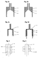
- FIGS. 2 a to d Possible embodiments of the upper thread guide 23 are shown in FIGS. 2 a to d displayed.
- Figs. A to c show variants in which the head part in the lower part engages, while variant d is just reversed. If that ever the outer part is more elastic, an externally attached reinforcement may be advantageous to one caused by the centrifugal force, to prevent unwanted expansion.
- FIGS. 3 and 4 Variants of the bearing 13 of the balloon constricting sleeve 11 are shown in FIGS. 3 and 4 shown.
- Fig. 3 shows an axis 16 which is provided with bearing tracks 17 for the balls of the bearing 13 is formed.
- the axis 16 thus forms the inner ring of the bearing 13.
- Den Outer ring of the bearing 13 forms a housing 18, each around the individual bearing, such as right in the figure, or around the entire storage and the engine 14 can be trained.
- Fig. 4 shows an embodiment in which the housing of the motor 14 as an outer ring 19 of the bearing 13 is formed and the axis 16 forms the stator of the motor 14.
Landscapes
- Engineering & Computer Science (AREA)
- Mechanical Engineering (AREA)
- Textile Engineering (AREA)
- Spinning Or Twisting Of Yarns (AREA)
Abstract
Description
Claims (19)
- Balloneinengungshülse (11) mit einem individuellen Antrieb (14) für eine Textilmaschine, vorzugsweise Spinn- oder Zwirnmaschine, dadurch gekennzeichnet, dass ihr Kopfteil (12) und die Achse (16) für ihren Antrieb aus einem Stück gefertigt sind.
- Balloneinengungshülse (11) nach Anspruch 1, dadurch gekennzeichnet, dass ihr Unterteil (15) in ihr Kopfteil (12) eingreift.
- Balloneinengungshülse (11) nach Anspruch 1, dadurch gekennzeichnet, dass ihr Kopfteil (15) in ihr Unterteil (12) eingreift.
- Balloneinengungshülse (11) nach einem der vorangegangenen Ansprüche, dadurch gekennzeichnet, dass der je äussere Teil (12 oder 15) an seiner Aussenseite durch ein zusätzliches Element (26) aus einem Material verstärkt ist, welches weniger elastisch ist.
- Balloneinengungshülse (11) nach einem der vorangegangenen Ansprüche, dadurch gekennzeichnet, dass ihr Unterteil (15) und ihr Kopfteil (12) lösbar mit einander verbunden sind.
- Balloneinengungshülse (11) nach Anspruch 5, dadurch gekennzeichnet, dass das Unterteil (15) austauschbar ist.
- Balloneinengungshülse (11) nach einem der Ansprüche 1-4, dadurch gekennzeichnet, dass ihr Unterteil (15) und ihr Kopfteil (12) fest mit einander verbunden sind.
- Balloneinengungshülse (11) nach Anspruch 5 oder 7, dadurch gekennzeichnet, dass ihr Unterteil (15) und ihr Kopfteil (12) chemisch mit einander verbunden sind.
- Balloneinengungshülse (11) nach Anspruch 7, dadurch gekennzeichnet, dass ihr Unterteil (15) und ihr Kopfteil (12) thermoplastisch mit einander verbunden sind.
- Balloneinengungshülse (11) nach Anspruch 5 oder 7, dadurch gekennzeichnet, dass ihr Unterteil (15) und ihr Kopfteil (12) mechanisch mit einander verbunden sind.
- Balloneinengungshülse (11) nach einem der vorangegangenen Ansprüche, dadurch gekennzeichnet, dass der untere Durchmesser des Kopfteils (12) grösser ist als der Durchmesser der Garnhülse (21) soweit sie in den Kopfteil eintauchen muss.
- Balloneinengungshülse (11) nach einem der vorangegangenen Ansprüche, dadurch gekennzeichnet, dass das Material, aus dem der Kopfteil (12) mit Achse (16) gefertigt ist, Wälzlagerstahl ist oder enthält.
- Balloneinengungshülse (11) nach einem der vorangegangenen Ansprüche, dadurch gekennzeichnet, dass ihr Kopfteil (12) mit einer zweireihigen Lagerung (13) versehen ist, der ein Antriebsmotor (14) vor-, zwischen- oder nachgelagert sein kann.
- Balloneinengungshülse (11) nach einem der vorangegangenen Ansprüche, dadurch gekennzeichnet, dass ihr Kopfteil (12) so ausgebildet ist, dass die Lagerbahnen (17) des Lagers oder der Lager (13) direkt in die Achse (16) und/oder in ein Gehäuse (18) eingeschliffen sind.
- Balloneinengungshülse (11) nach einem der vorangegangenen Ansprüche, dadurch gekennzeichnet, dass ihr Kopfteil (12) so ausgebildet ist, dass die Lagerbahnen (17) des Lagers oder der Lager (13) in einen separaten äusseren Lagerring (19) integriert sind.
- Balloneinengungshülse (11) nach einem der vorangegangenen Ansprüche, dadurch gekennzeichnet, dass die Form ihres Unterteils (15) in Fadenlaufrichtung zunächst zylindrisch oder leicht konisch und dann konisch ist.
- Balloneinengungshülse (11) nach einem der vorangegangenen Ansprüche, dadurch gekennzeichnet, dass der Fadenführer der Hülse austauschbar ist.
- Balloneinengungshülse (11) nach einem der vorangegangenen Ansprüche, dadurch gekennzeichnet, dass die Form des Unterteils (15) abhängig von der Struktur des zu verspinnenden Materials und/oder der Spinnmaschine gestaltet ist.
- Verfahren zur Herstellung von Balloneinengungshülsen (11) gemäss einem der vorangegangen Ansprüche.
Applications Claiming Priority (2)
| Application Number | Priority Date | Filing Date | Title |
|---|---|---|---|
| CH2692004 | 2004-02-19 | ||
| CH2692004 | 2004-02-19 |
Publications (2)
| Publication Number | Publication Date |
|---|---|
| EP1568804A2 true EP1568804A2 (de) | 2005-08-31 |
| EP1568804A3 EP1568804A3 (de) | 2006-05-03 |
Family
ID=34744470
Family Applications (1)
| Application Number | Title | Priority Date | Filing Date |
|---|---|---|---|
| EP05000359A Withdrawn EP1568804A3 (de) | 2004-02-19 | 2005-01-11 | Balloneinengungshülsen für Textilmaschinen |
Country Status (2)
| Country | Link |
|---|---|
| EP (1) | EP1568804A3 (de) |
| CN (1) | CN1657672A (de) |
Cited By (1)
| Publication number | Priority date | Publication date | Assignee | Title |
|---|---|---|---|---|
| RU2460831C1 (ru) * | 2011-05-20 | 2012-09-10 | Государственное образовательное учреждение высшего профессионального образования "Ивановская государственная текстильная академия" (ИГТА) | Баллоноограничитель прядильной или прядильно-крутильной машины |
Family Cites Families (10)
| Publication number | Priority date | Publication date | Assignee | Title |
|---|---|---|---|---|
| US1618519A (en) * | 1925-03-04 | 1927-02-22 | Otto George Johan Stru Roysanc | Twisting device |
| US2008609A (en) * | 1934-05-18 | 1935-07-16 | Thomas A Darr | Interchangeable spinning cap |
| US2500827A (en) * | 1946-11-28 | 1950-03-14 | Ira Ickringill And Company Ltd | Flyer for spinning frame |
| GB631838A (en) * | 1947-06-27 | 1949-11-10 | Douglas Fraser & Sons Ltd | Improvements in spinning and like textile frames |
| US2833111A (en) * | 1955-10-20 | 1958-05-06 | Spinnerei Karl Marx Veb | Cap spinning frames and cap twisting frames |
| FR1245474A (fr) * | 1960-01-20 | 1960-09-26 | Perfectionnement aux cloches pour machines à filer | |
| IT1221716B (it) * | 1987-08-10 | 1990-07-12 | Cerit Spa | Perfezionamenti ad un sistema di filatura a limitatore di ballon rotante |
| DE3732968A1 (de) * | 1987-09-30 | 1989-04-20 | Zinser Textilmaschinen Gmbh | Trichter fuer eine trichterspinnvorrichtung |
| DE4012016A1 (de) * | 1990-04-13 | 1991-10-24 | Zinser Textilmaschinen Gmbh | Spinn- und zwirnvorrichtung |
| JP2001040535A (ja) * | 1999-07-28 | 2001-02-13 | Murata Mach Ltd | 紡績装置 |
-
2005
- 2005-01-11 EP EP05000359A patent/EP1568804A3/de not_active Withdrawn
- 2005-02-18 CN CN 200510009334 patent/CN1657672A/zh active Pending
Cited By (1)
| Publication number | Priority date | Publication date | Assignee | Title |
|---|---|---|---|---|
| RU2460831C1 (ru) * | 2011-05-20 | 2012-09-10 | Государственное образовательное учреждение высшего профессионального образования "Ивановская государственная текстильная академия" (ИГТА) | Баллоноограничитель прядильной или прядильно-крутильной машины |
Also Published As
| Publication number | Publication date |
|---|---|
| EP1568804A3 (de) | 2006-05-03 |
| CN1657672A (zh) | 2005-08-24 |
Similar Documents
| Publication | Publication Date | Title |
|---|---|---|
| EP2082131B1 (de) | Mast für eine windturbine | |
| DE102010043785B3 (de) | Schraubfundament mit Abschnitten veränderlicher Durchmesser | |
| EP0220546A1 (de) | Spinnvorrichtung zum Offenend-Spinnen | |
| DE3734544A1 (de) | Offenend-spinnvorrichtung und verfahren zu deren herstellung | |
| CH701482A2 (de) | Spindellagerung. | |
| DE1510310B1 (de) | Drehteller zum Ablegen von Faserbaendern in Spinnkannen | |
| WO2012123270A2 (de) | Rotor für eine elektrische maschine und elektrische maschine | |
| CH697457B1 (de) | Druckwalzeneinheit. | |
| CH645417A5 (de) | Kerngarn, verfahren zu dessen herstellung und anordnung zum ausfuehren dieses verfahrens. | |
| EP1567699B1 (de) | Webmaschine | |
| DE7331545U (de) | Vorrichtung zum uebertragen von garndrehungen bei ringspinnmaschinen | |
| DE10112202A1 (de) | Walze | |
| EP1310588A2 (de) | Antriebsanordnung für das Webblatt einer Webmaschine | |
| EP1568804A2 (de) | Balloneinengungshülsen für Textilmaschinen | |
| DE102012101001A1 (de) | Garnbildungselement für eine Spinnstelle einer Luftspinnmaschine mit einer wendelförmigen Führung sowie Verfahren zur Herstellung eines Garns | |
| DE102005059028A1 (de) | Fadenführer | |
| DE1510705A1 (de) | Streckwerk fuer Spinnereimaschinen | |
| DE19916492A1 (de) | Kurbelwelle für eine Brennkraftmaschine | |
| DE2918447A1 (de) | Naehmaschine | |
| DE29817903U1 (de) | Gewichtskörpersystem | |
| EP0929706B1 (de) | Verfahren und vorrichtung zum umeinanderschlingen von wenigstens zwei laufenden fäden | |
| DE352206C (de) | Maschine mit im wesentlichen parallel zur Kurbelwelle angeordneten Zylindern und sich doppelkegelfoermig bewegendem, mittels Kardangelenkes aufgehaengtem Taumelstueck | |
| DE69510730T2 (de) | Rotor für Drahtschlingenlegekopf | |
| DE1785358A1 (de) | Verfahren und Vorrichtung zur Drehfoerderung von Fasern | |
| DE102007015411A1 (de) | Kurvenscheibe für Exzentermaschine einer Webmaschine |
Legal Events
| Date | Code | Title | Description |
|---|---|---|---|
| PUAI | Public reference made under article 153(3) epc to a published international application that has entered the european phase |
Free format text: ORIGINAL CODE: 0009012 |
|
| AK | Designated contracting states |
Kind code of ref document: A2 Designated state(s): AT BE BG CH CY CZ DE DK EE ES FI FR GB GR HU IE IS IT LI LT LU MC NL PL PT RO SE SI SK TR |
|
| AX | Request for extension of the european patent |
Extension state: AL BA HR LV MK YU |
|
| PUAL | Search report despatched |
Free format text: ORIGINAL CODE: 0009013 |
|
| AK | Designated contracting states |
Kind code of ref document: A3 Designated state(s): AT BE BG CH CY CZ DE DK EE ES FI FR GB GR HU IE IS IT LI LT LU MC NL PL PT RO SE SI SK TR |
|
| AX | Request for extension of the european patent |
Extension state: AL BA HR LV MK YU |
|
| AKX | Designation fees paid | ||
| REG | Reference to a national code |
Ref country code: DE Ref legal event code: 8566 |
|
| STAA | Information on the status of an ep patent application or granted ep patent |
Free format text: STATUS: THE APPLICATION IS DEEMED TO BE WITHDRAWN |
|
| 18D | Application deemed to be withdrawn |
Effective date: 20061107 |