EP1568332B1 - Elektrodenanordnung für ein chirurgisches Instrument zur elektrothermischen Koagulation im Gewebe - Google Patents
Elektrodenanordnung für ein chirurgisches Instrument zur elektrothermischen Koagulation im Gewebe Download PDFInfo
- Publication number
- EP1568332B1 EP1568332B1 EP05103696A EP05103696A EP1568332B1 EP 1568332 B1 EP1568332 B1 EP 1568332B1 EP 05103696 A EP05103696 A EP 05103696A EP 05103696 A EP05103696 A EP 05103696A EP 1568332 B1 EP1568332 B1 EP 1568332B1
- Authority
- EP
- European Patent Office
- Prior art keywords
- electrodes
- surgical instrument
- electrode
- front cylinder
- electrode arrangement
- Prior art date
- Legal status (The legal status is an assumption and is not a legal conclusion. Google has not performed a legal analysis and makes no representation as to the accuracy of the status listed.)
- Expired - Lifetime
Links
Images


Classifications
-
- A—HUMAN NECESSITIES
- A61—MEDICAL OR VETERINARY SCIENCE; HYGIENE
- A61B—DIAGNOSIS; SURGERY; IDENTIFICATION
- A61B18/00—Surgical instruments, devices or methods for transferring non-mechanical forms of energy to or from the body
- A61B18/04—Surgical instruments, devices or methods for transferring non-mechanical forms of energy to or from the body by heating
- A61B18/12—Surgical instruments, devices or methods for transferring non-mechanical forms of energy to or from the body by heating by passing a current through the tissue to be heated, e.g. high-frequency current
- A61B18/14—Probes or electrodes therefor
- A61B18/1492—Probes or electrodes therefor having a flexible, catheter-like structure, e.g. for heart ablation
-
- A—HUMAN NECESSITIES
- A61—MEDICAL OR VETERINARY SCIENCE; HYGIENE
- A61B—DIAGNOSIS; SURGERY; IDENTIFICATION
- A61B18/00—Surgical instruments, devices or methods for transferring non-mechanical forms of energy to or from the body
- A61B18/04—Surgical instruments, devices or methods for transferring non-mechanical forms of energy to or from the body by heating
- A61B18/12—Surgical instruments, devices or methods for transferring non-mechanical forms of energy to or from the body by heating by passing a current through the tissue to be heated, e.g. high-frequency current
- A61B18/14—Probes or electrodes therefor
- A61B18/1477—Needle-like probes
-
- A—HUMAN NECESSITIES
- A61—MEDICAL OR VETERINARY SCIENCE; HYGIENE
- A61B—DIAGNOSIS; SURGERY; IDENTIFICATION
- A61B17/00—Surgical instruments, devices or methods, e.g. tourniquets
- A61B2017/00017—Electrical control of surgical instruments
- A61B2017/00022—Sensing or detecting at the treatment site
- A61B2017/00084—Temperature
-
- A—HUMAN NECESSITIES
- A61—MEDICAL OR VETERINARY SCIENCE; HYGIENE
- A61B—DIAGNOSIS; SURGERY; IDENTIFICATION
- A61B18/00—Surgical instruments, devices or methods for transferring non-mechanical forms of energy to or from the body
- A61B2018/00005—Cooling or heating of the probe or tissue immediately surrounding the probe
- A61B2018/00011—Cooling or heating of the probe or tissue immediately surrounding the probe with fluids
- A61B2018/00023—Cooling or heating of the probe or tissue immediately surrounding the probe with fluids closed, i.e. without wound contact by the fluid
-
- A—HUMAN NECESSITIES
- A61—MEDICAL OR VETERINARY SCIENCE; HYGIENE
- A61B—DIAGNOSIS; SURGERY; IDENTIFICATION
- A61B18/00—Surgical instruments, devices or methods for transferring non-mechanical forms of energy to or from the body
- A61B2018/00005—Cooling or heating of the probe or tissue immediately surrounding the probe
- A61B2018/00011—Cooling or heating of the probe or tissue immediately surrounding the probe with fluids
- A61B2018/00029—Cooling or heating of the probe or tissue immediately surrounding the probe with fluids open
-
- A—HUMAN NECESSITIES
- A61—MEDICAL OR VETERINARY SCIENCE; HYGIENE
- A61B—DIAGNOSIS; SURGERY; IDENTIFICATION
- A61B18/00—Surgical instruments, devices or methods for transferring non-mechanical forms of energy to or from the body
- A61B2018/00053—Mechanical features of the instrument of device
- A61B2018/00059—Material properties
- A61B2018/00071—Electrical conductivity
- A61B2018/00083—Electrical conductivity low, i.e. electrically insulating
-
- A—HUMAN NECESSITIES
- A61—MEDICAL OR VETERINARY SCIENCE; HYGIENE
- A61B—DIAGNOSIS; SURGERY; IDENTIFICATION
- A61B18/00—Surgical instruments, devices or methods for transferring non-mechanical forms of energy to or from the body
- A61B2018/00053—Mechanical features of the instrument of device
- A61B2018/00107—Coatings on the energy applicator
- A61B2018/00148—Coatings on the energy applicator with metal
-
- A—HUMAN NECESSITIES
- A61—MEDICAL OR VETERINARY SCIENCE; HYGIENE
- A61B—DIAGNOSIS; SURGERY; IDENTIFICATION
- A61B18/00—Surgical instruments, devices or methods for transferring non-mechanical forms of energy to or from the body
- A61B2018/00571—Surgical instruments, devices or methods for transferring non-mechanical forms of energy to or from the body for achieving a particular surgical effect
- A61B2018/00577—Ablation
-
- A—HUMAN NECESSITIES
- A61—MEDICAL OR VETERINARY SCIENCE; HYGIENE
- A61B—DIAGNOSIS; SURGERY; IDENTIFICATION
- A61B18/00—Surgical instruments, devices or methods for transferring non-mechanical forms of energy to or from the body
- A61B2018/00571—Surgical instruments, devices or methods for transferring non-mechanical forms of energy to or from the body for achieving a particular surgical effect
- A61B2018/00589—Coagulation
-
- A—HUMAN NECESSITIES
- A61—MEDICAL OR VETERINARY SCIENCE; HYGIENE
- A61B—DIAGNOSIS; SURGERY; IDENTIFICATION
- A61B18/00—Surgical instruments, devices or methods for transferring non-mechanical forms of energy to or from the body
- A61B2018/00636—Sensing and controlling the application of energy
- A61B2018/00773—Sensed parameters
- A61B2018/00791—Temperature
- A61B2018/00815—Temperature measured by a thermistor
-
- A—HUMAN NECESSITIES
- A61—MEDICAL OR VETERINARY SCIENCE; HYGIENE
- A61B—DIAGNOSIS; SURGERY; IDENTIFICATION
- A61B18/00—Surgical instruments, devices or methods for transferring non-mechanical forms of energy to or from the body
- A61B18/04—Surgical instruments, devices or methods for transferring non-mechanical forms of energy to or from the body by heating
- A61B18/12—Surgical instruments, devices or methods for transferring non-mechanical forms of energy to or from the body by heating by passing a current through the tissue to be heated, e.g. high-frequency current
- A61B18/1206—Generators therefor
- A61B2018/1246—Generators therefor characterised by the output polarity
- A61B2018/126—Generators therefor characterised by the output polarity bipolar
-
- A—HUMAN NECESSITIES
- A61—MEDICAL OR VETERINARY SCIENCE; HYGIENE
- A61B—DIAGNOSIS; SURGERY; IDENTIFICATION
- A61B18/00—Surgical instruments, devices or methods for transferring non-mechanical forms of energy to or from the body
- A61B18/04—Surgical instruments, devices or methods for transferring non-mechanical forms of energy to or from the body by heating
- A61B18/12—Surgical instruments, devices or methods for transferring non-mechanical forms of energy to or from the body by heating by passing a current through the tissue to be heated, e.g. high-frequency current
- A61B18/14—Probes or electrodes therefor
- A61B2018/1405—Electrodes having a specific shape
- A61B2018/1425—Needle
-
- A—HUMAN NECESSITIES
- A61—MEDICAL OR VETERINARY SCIENCE; HYGIENE
- A61B—DIAGNOSIS; SURGERY; IDENTIFICATION
- A61B18/00—Surgical instruments, devices or methods for transferring non-mechanical forms of energy to or from the body
- A61B18/18—Surgical instruments, devices or methods for transferring non-mechanical forms of energy to or from the body by applying electromagnetic radiation, e.g. microwaves
- A61B18/20—Surgical instruments, devices or methods for transferring non-mechanical forms of energy to or from the body by applying electromagnetic radiation, e.g. microwaves using laser
- A61B2018/2015—Miscellaneous features
- A61B2018/2025—Miscellaneous features with a pilot laser
-
- A—HUMAN NECESSITIES
- A61—MEDICAL OR VETERINARY SCIENCE; HYGIENE
- A61B—DIAGNOSIS; SURGERY; IDENTIFICATION
- A61B90/00—Instruments, implements or accessories specially adapted for surgery or diagnosis and not covered by any of the groups A61B1/00 - A61B50/00, e.g. for luxation treatment or for protecting wound edges
- A61B90/30—Devices for illuminating a surgical field, the devices having an interrelation with other surgical devices or with a surgical procedure
- A61B2090/306—Devices for illuminating a surgical field, the devices having an interrelation with other surgical devices or with a surgical procedure using optical fibres
Definitions
- the invention relates to an electrode assembly for a surgical instrument for the electrothermal coagulation of tissue, which includes a front cylinder at the distal end of the instrument with a distal tip, with a proximal front cylinder following carrier, and with two electrodes which are connected to an AC voltage source.
- an electrode - also referred to as a neutral electrode - as a large-area electrode in the vicinity of the treatment site attached to the skin of the patient and fixed there and grounded, or connected to ground.
- a second electrode handled by the operator - also referred to as the active electrode - is connected to the AC voltage source.
- the shape of the electrode is adapted to the particular application, in particular to the size of the tissue area to be treated, so that both the duration of the operation and the thermal load of the affected organ or body area are justifiable and only coagulate the desired tissue area.
- both electrodes are connected to an RF generator and arranged in mutually fixed dimensions, for example on an insulating support and placed by the surgeon in the immediate vicinity of the treatment site and usually actively performed.
- a bipolar electrode arrangement with a fluid channel via which irrigation fluid can be introduced into the engagement area.
- Two or three electrodes are arranged as a cone section on a cone-shaped distal tip of the instrument, which can be inserted into the tissue, wherein the electromagnetic RF field is formed between the electrodes and should coagulate the surrounding tissue.
- a device for high-frequency coagulation with at least one front and one rear electrode is known, each at least partially cylindrical and in the direction of a common longitudinal axis are arranged one behind the other and have exposed outer surfaces that have different dimensions in the direction of the longitudinal axis.
- a surgical instrument that treats tissue in an electrically conductive liquid medium by means of a bipolar electrode assembly connected to an RF generator, wherein the active electrode of the electrode assembly has an exposed portion for tissue treatment and the return electrode of the electrode assembly has an exposed contact surface with the tissue Have liquid.
- the known surgical instruments for bipolar RF thermotherapy are often expensive to produce, and they often have disadvantages for the various fields of application, which often lead to a locally inaccurate tissue treatment, in particular the tissue to be treated partially not achieved, or benign tissue thermally overloaded.
- the object of the invention is therefore to develop an electrode assembly for a surgical instrument of the type mentioned in such a way that it is easy to manufacture and use and precise localized treatment of the tissue - while preserving the surrounding healthy tissue - allows.
- the electrode assembly device is particularly simple in construction, namely, the front cylinder forms an electrode, and that isolated via an insulator element, subsequent outer conductor forms the second electrode, so that the AC voltage source via the rod-shaped inner conductor, the is separated by an insulation tube outer conductor, is connected to the front cylinder and from the outside directly to the outer conductor.
- the electrode arrangement for an instrument can be designed to be flexible, so that the inner conductor, outer conductor, the insulation tube and possibly also the insulation element then consist of an elastic material.
- the bipolar electrode assembly may be easier to spend at the particular treatment site.
- inner conductor and outer conductor can be rigid and straight line, in which case the front cylinder and outer conductor are arranged coaxially aligned with each other and then can be moved by a linear translation movement to the treatment site.
- the outer conductor and the front cylinder have substantially the same outer diameter in order to realize a disability-free sliding movement of the electrode assembly in the tissue.
- the front cylinder forms over its axial length, which is not covered by the insulating element, the first electrode and the outer conductor forms over the full axial length section, as far as it is not covered by the insulating element, the second cylindrical electrode.
- the axial length of the electrodes is preferably greater than the axial length of the insulating element and also larger than the outer diameter of the front cylinder and the outer conductor.
- the length of the outer conductor is a multiple of the length of the front cylinder.
- the electromagnetic field can shift outwardly into adjacent tissue area because of a correspondingly long second electrode, so that the electromagnetic field, when adjacent to the outer surface of the tissue has become highly resistive, can migrate radially outward, while still ending on the second electrode.
- the front cylinder which is in electrical connection with the inner conductor, and the outer conductor are separated from each other by an insulating ring body.
- the insulating ring body is made of translucent or partially translucent material, and in the ring body, a light source is arranged, which emits its light through the ring body through - preferably as stray light - to the outside.
- the inner conductor has a hollow channel which terminates in the insulating ring body and receives an optical waveguide.
- the inner conductor is in the area of the annular body radially into the fiber core of the optical waveguide with incisions provided so that light exits radially at these incisions from the optical waveguide and makes visible through ring body that zone of the bipolar electrode assembly for the attending physician, which lies between the two electrodes, in the So the coagulation of the tissue takes place in each case.
- the attending physician therefore always sees directly with his eye the point at which coagulation takes place. It is thus possible a particularly accurate local treatment of the tissue.
- the tip of the front cylinder can be conical or wedge-shaped as needed.
- the front cylinder is realized as a one-piece metal tube or metal rod, the distal end of which is sharpened. A distal portion of the metal tube or metal rod forms the first electrode. Adjacent thereto, an insulating layer is applied to the carrier, and in the proximal region of this insulating layer, a cylindrical metal layer is then deposited on the insulating layer and forms the second, cylindrical electrode.
- the insulating layer can be realized by a plastic tube on which - as a second electrode - a metal coating is applied.
- the metal carrier with distal tip provides one bipolar electrode assembly in the form of a cannula or needle and is particularly suitable for the therapy of extended end vessels such. B. broom vans.
- the electrode assembly is pierced with its tip in the longitudinal direction in the extended vessel.
- the blood and the vessel wall coagulate primarily around the first electrode.
- the vessel contracts, so that a closure is achieved, with the result that then no more blood can flow into the vessel, whereby this is no longer visible through the skin and the desired cosmetic effect is achieved.
- Insulator layers which are used in the bipolar electrode arrangements are particularly advantageously used made of ceramic material.
- the advantage of this material is that it offers a high mechanical strength and can be produced by means of an electrolytic anodization (for example on titanium in the form of titanium oxide, or aluminum in the form of aluminum oxide in a simple manner.
- the layer thickness depends on the electrical voltage used in the electrolysis.
- various titanium alloys are also suitable as starting material, onto which the ceramic layer is produced by anodic oxidation. In order to perform such a complete or partial coating of titanium or suitable titanium alloys or aluminum, first the corresponding metal body is chemically pre-cleaned to obtain fat-free and oxide-free surfaces. Following this, the points not to be coated are masked.
- the masking can be realized by special lacquers or layers but also by heat shrink tubing.
- the starting material ie, titanium, titanium alloys or aluminum
- the starting material is to be electrically contacted and subjected to voltage as an anode.
- a corresponding molar acid is to be used in aqueous solution.
- the molar solutions in question are between 0.1 to 1 molar H 2 SO 4 (sulfuric acid) or H 3 PO 4 (phosphoric acid).
- H 2 SO 4 sulfuric acid
- H 3 PO 4 phosphoric acid
- the DC voltages and currents to be used are between 10V and 500V at maximum currents of 1 A.
- the oxidation process undergoes several oxidation states (titanium oxides) depending on the length of the process.
- the layer thicknesses to be achieved with these methods are on the order of 20 to 30 ⁇ m.
- the different refraction of light at the interface with the metal enables it to be displayed proportionally over a color spectrum.
- special paramagnetic electrodes made of titanium or titanium alloys such as TiAl 6 V 4 can be efficiently provided with a dielectric ceramic layer in terms of layer thickness and / or color.
- the tribological properties are excellent, in order to increase abrasion resistance and surface quality if necessary.
- These colored ceramic layers are also suitable for stable marking of needles, cannulas or probes. By choosing the layer thickness, a proportional interference color is to be selected. It can be used to adjust colors from gray, gold, violet to blue.
- At least one of the connecting lines which serve to connect the electrodes, at its end a portion of spring metal, preferably spring wire, which has such a shape that it is in the hollow channel - within the electrodes - radially outward jammed against the inner surface of the electrodes and thereby makes the electrical contact sufficiently safe and reliable.
- the spring metal section of the connection lines formed in this way is preferably wound into a spiral spring, which is acted upon by a predetermined tension in the spiral wire whose winding thus has a reduced diameter under this tensile stress, in order to be able to introduce from the outside in a simple manner into the cavity of the electrodes.
- Fig. 1 shows a longitudinal section through a first embodiment of a bipolar electrode assembly which is part of a surgical instrument for the electrothermal coagulation of tissue.
- the electrode assembly includes an electrically conductive front cylinder 10 that forms the distal end of the instrument, that is, remote from the user of the instrument.
- the front cylinder ends at its free end in a tip 12, which terminates conically pointed in the illustrated embodiment.
- To the front cylinder 10 includes a tubular outer conductor 20, which receives in its interior an insulation tube 30 through which a rod-shaped inner conductor 40 passes.
- the rod-shaped inner conductor 40 has at its distal end an external thread, which is screwed into a corresponding inaxial longitudinal direction extending internal thread and is electrically and mechanically connected by means of this screw 14 with the front cylinder 10.
- an insulator member 50 is arranged, which has a radial partition 52 between the front cylinder 10 and the distal end wall of the outer conductor 20 and the insulation tube 30. Externally on the dividing wall 52, the insulator element 50 merges into an enveloping wall 54 which, in the illustrated embodiment, tightly surrounds the outer surface of the front cylinder 10, but which, in an alternative embodiment, may also surround the outer surface of the outer conductor 20.
- the exposed outer surface of the front cylinder 10 forms a second electrode 4.
- the two electrodes - at the proximal end of the electrode assembly - a high frequency AC voltage source is connected when the bipolar electrode assembly in the treated human or animal tissue is introduced and the tissue is to be coagulated by the heat effect of the electric field.
- Fig. 2 shows a second embodiment of the bipolar electrode assembly according to the invention, in turn, a front cylinder 10 terminates in a conical distal tip 12, again a rod-shaped metallic inner conductor is surrounded by an insulating tube 30, which in turn is surrounded by a metallic tubular outer conductor 20.
- an insulator member 50 is provided between the front cylinder 10 and the end wall of the outer conductor and the insulation tube 30, which has the shape of an annular body 58 and has a predetermined axial length, which keeps the front cylinder 10 and the outer conductor 20 at a distance.
- the front cylinder 10 is made of metal and serves as a cylindrical first electrode 2.
- the outer conductor 20 is also made of metal and serves as a cylindrical second electrode 4.
- the front cylinder 10 is connected by means of a screw 14 with the inner conductor 40.
- an RF AC voltage source is connected at the proximal end of the electrode assembly, between the outer conductor 20 and the inner conductor 40, an RF AC voltage source is connected when an electrothermal coagulation of surrounding tissue is to be performed,
- Fig. 3 shows a the Fig. 1 and 2 corresponding embodiment of a bipolar electrode arrangement in which the insulator element 50 is cup-shaped, wherein the cylindrical enveloping wall 54 is seated in a corresponding annular recess 11 of the front cylinder 10.
- the radial partition wall 52 of the insulator element 50 is guided proximally tubular - with the outer diameter of the insulating tube 30 - against the insulation tube 30, which ends a corresponding axial length in front of the distal end wall of the outer conductor 20.
- Fig. 4 shows a fourth embodiment of a bipolar electrode assembly 1 according to the invention, which largely according to the arrangement Fig. 1 corresponds, wherein the same parts are provided with the same reference numerals.
- a hollow channel through which passes an optical waveguide, which leads visible light to the distal tip 12 of the electrode assembly, when the optical fiber proximal, for example is fed with visible laser light.
- the optical waveguide 60 includes a cladding 62 surrounding the photoconductive core 64. Around the mantle, a cladding can also be provided.
- Fig. 5 shows a further embodiment of the invention, which is largely the embodiment according to Fig. 4 However, wherein the front cylinder 10 has a wedge-shaped tip 12 at its distal end. Again, through the inner conductor 40 and thereafter also by the front cylinder 10, a central hollow channel is provided, through which an optical waveguide 60 passes with its sheath 62 and the core 64 to the distal tip 12 and the user of the electrode assembly - especially in a treatment of tissue in thin-walled body parts - each visually indicates the position of the distal tip 12 in the tissue.
- Fig. 6 shows a further embodiment of the bipolar electrode assembly 1 according to the invention, which is substantially the embodiment according to Fig. 2 or 4 equivalent.
- annular body 58 is provided, through which the inner conductor 40 passes axially to the front cylinder 10.
- the inner conductor 40 has a central hollow channel which extends to the distal end of the annular body 58 and contains an optical waveguide 60.
- the ring body 58 is formed of transparent or semi-transparent material and allows light to pass to the outside.
- annular body 58 In the area of the annular body 58, radial notches 42 are introduced into the inner conductor as far as into the core 64 of the optical waveguide, with the result that light passes radially outward from the inner conductor 40 and through the annular body 58 through this grinding in, so that the Operator, the position of the electric field, which is formed between the first electrode 2 and the second electrode 4, when 20 RF power is fed to the inner conductor 40 and the outer conductor, can be optically visible.
- the annular body 48 is preferably made of such a material or its surface has such a structure that the light 3 emerging from the optical waveguide passes outward as stray light.
- All illustrated embodiments of the bipolar electrode assembly 1 have a substantially circular cross-section with radius R and over its length a homogeneous cross-section as possible. Discrepancies in the outer diameter are kept as small as possible in order to be able to introduce the electrode arrangement into the tissue with ease.
- the axial length of the electrodes is larger in all the illustrated embodiments than the distance of the electrodes, which is substantially of the order of the outer diameter. In this dimensioning, there is an advantageous local concentration of the coagulation process and a sufficient strength of the electric field.
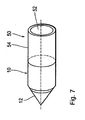
- Fig. 7 shows a front cylinder 10, which consists for example of aluminum or titanium or a titanium alloy and was provided by anodic oxidation, ie a proximal end portion with a ceramic layer which forms the insulating member 50, the partition wall 52 is formed at the proximal end of the front cylinder, and its Hüllwand 54 extends outwardly around an axial longitudinal portion of the front cylinder.
- a front cylinder 10 which consists for example of aluminum or titanium or a titanium alloy and was provided by anodic oxidation, ie a proximal end portion with a ceramic layer which forms the insulating member 50, the partition wall 52 is formed at the proximal end of the front cylinder, and its Hüllwand 54 extends outwardly around an axial longitudinal portion of the front cylinder.
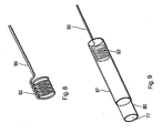
- the 8 and 9 show an end portion formed as a spiral spring 92 of a connecting line 90 which is inserted into a hollow channel 77 of a metal tube 80 and under radial pressure against the inner surface of the tube 80 and contacts this.
- an insulating layer 87 is shown on the metal tube 80.
Description
- Die Erfindung betrifft eine Elektrodenanordnung für ein chirurgisches Instrument zur elektrothermischen Koagulation von Gewebe, welches einen Frontzylinder am distalen Ende des Instrumentes mit einer distalen Spitze enthält, mit einem proximal an Frontzylinder anschließenden Träger, und mit zwei Elektroden, die an eine Wechselspannungsquelle anschließbar sind.
- Die Anwendung hochfrequenter Wechselströme (beispielsweise im Frequenzbereich von 300 KHz bis 2 MHz) zur Erzeugung hoher Temperaturen zu Gewebekoagulation und zur Gewebetrennung zu verwenden ist in der Chirurgie seit langem bekannt, in der Praxis werden zur Einbringung des HF-Stromes in das Gewebe sogenannte mono-polare Elektrodenanordnungen oder bipolare Elektrodenanordnungen eingesetzt.
- Bei den monopolaren Anordnungen wird eine Elektrode - auch als Neutralelektrode bezeichnet - als großflächige Elektrode in der Nähe des Behandlungsortes auf die Haut des Patienten angesetzt und dort fixiert und geerdet, bzw. mit Masse verbunden. Eine zweite vom Operateur gehandhabte Elektrode - auch ais Aktivelektrode bezeichnet - ist mit der Wechselspannungsquelle verbunden. Die Elektrode ist in ihrer Form an die jeweilige Anwendung, insbesondere an die Größe des zu behandelnden Gewebebereiches so angepasst, dass sowohl die Operationsdauer als auch die thermische Belastung des betroffenen Organes bzw. Körperbereiches vertretbar sind und nur den gewünschten Gewebebereich koagulieren.
- Bei Anordnungen zur bipolaren HF-Thermotherapie sind beide Elektroden mit einem HF-Generator verbunden und in miteinander festgelegte Abmessungen, beispielsweise auf einem isolierenden Träger angeordnet und werden vom Operateur in unmittelbarer Nähe der Behandlungsstelle platziert und in der Regel auch aktiv geführt.
- Aus der
WO 97/17009 - Aus der
WO 96/34569 - Aus der
DE 39 30 451 A1 ist eine Vorrichtung für Hochfrequenzkoagulation mit mindestens einer vorderen und einer hinteren Elektrode bekannt, die jeweils zumindest teilweise zylinderförmig und in Richtung einer gemeinsamen Längsachse hintereinander angeordnet sind sowie freiliegende Außenflächen aufweisen, die unterschiedliche Abmessungen in Richtung der Längsachse haben. - Aus der
WO 97/00647 - Aus der
US 4,832,048 sowie aus derWO 95/10320 WO 99/11186 EP 96 945 879.3 W098/19613 WO96/183 W081/03272 - Die bekannten chirurgischen Instrumente zur bipolaren HF-Thermotherapie sind oftmals aufwendig in der Herstellung, und sie besitzen für die verschiedenen Anwendungsgebiete oftmals Nachteile, die oftmals zu einer lokal ungenauen Gewebebehandlung führen, die insbesondere das zu behandelnde Gewebe teilweise nicht erreicht, bzw. gutartiges Gewebe thermisch überlastet.
- Aufgabe der Erfindung ist es daher, eine Elektrodenanordnung für ein chirurgisches Instrument der eingangs genannten Art derart weiterzubilden, dass es einfach herstellbar und einsetzbar ist und eine präzise lokalisierbare Behandlung des Gewebes - bei gleichzeitiger Schonung des umgebenden gesunden Gewebes - ermöglicht.
- Diese Aufgabe wird gelöst durch eine Elektrodenanordnung für ein chirurgisches Instrument zur elektrothermischen Koagulation von Gewebe gemäß Anspruch 1.
- Die Vorteile der Erfindung liegen insbesondere darin, dass die Elektrodenanordnung Gerät besonders einfach aufgebaut ist, wobei nämlich der Frontzylinder eine Elektrode bildet, und dass der über ein Isolatorelement isolierte, anschließende Außenleiter die zweite Elektrode bildet, so dass die Wechselspannungsquelle über den stabförmigen Innenleiter, der durch einen Isolationsschlauchaußenleiter getrennt ist, an den Frontzylinder und von außen direkt an den Außenleiter anschließbar ist.
- Je nach Einsatzzweck läßt sich die Elektrodenanordnung für ein Instrument flexibel ausbilden, so dass dann Innenleiter, Außenleiter, der Isolationsschlauch und ggf. auch das Isolationselement aus einem elastischen Material bestehen. Bei einem derartigen flexiblen chirurgischen Instrument lässt sich die bipolare Elektrodenanordnung unter Umständen leichter an den speziellen Behandlungsort verbringen. Alternativ lassen sich jedoch auch Innenleiter und Außenleiter starr und geradlinig ausbilden, wobei dann Frontzylinder und Außenleiter koaxial zueinander fluchtend angeordnet sind und dann durch eine geradlinige Translationsbewegung an den Behandlungsort verbracht werden können. Bei bestimmten Behandlungsorten kann es auch besonders vorteilhaft sein, das Instrument in Längsrichtung abzuwinkeln.
- In allen Ausführungsformen besitzt der Außenleiter und der Frontzylinder im wesentlichen denselben Außendurchmesser, um eine behinderungsfreie Gleitbewegung der Elektrodenanordnung im Gewebe zu realisieren.
- Bevorzugt bildet der Frontzylinder über seinen axialen Längenabschnitt, welcher nicht vom Isolationselement bedeckt ist, die erste Elektrode und der Außenleiter bildet über den vollen axialen Längenabschnitt, soweit dieser nicht vom Isolationselement bedeckt ist, die zweite zylindrische Elektrode. Die axiale Länge der Elektroden ist bevorzugt größer als die axiale Länge des Isolationselementes und auch größer als der Außendurchmesser des Frontzylinders und des Außenleiters. Bevorzugt beträgt die Länge des Außenleiters ein Mehrfaches der Länge des Frontzylinders. Wenn bei dieser Ausführungsform das an die Außenfläche des Instrumentes angrenzende Gewebe koaguliert ist und dadurch hochohmig wird, so kann sich bei dieser Ausführungsform der Erfindung das elektromagnetische Feld nach außen in angrenzende Gewebebereich hin verlagern, weil eine entsprechend lange zweite Elektrode vorhanden ist, so dass das elektromagnetische Feld, wenn an die Außenfläche angrenzend das Gewebe hochohmig geworden ist, radial nach außen wandern kann und dabei immer noch auf der zweiten Elektrode endet. Bei dieser Ausführungsform ist es also möglich, eine definiert in das Gewebe hineinwandernde Koagulation zu realisieren, die zum Ende kommt, wenn sich das Feld von der ersten Elektrode bis zum proxialen Ende der zweiten Elektrode erstreckt.
- Umgekehrt hat sich gezeigt, dass der Beginn der Koagulation dann optimal ist, wenn die beiden Elektroden voneinander einen relativ geringen axialen Abstand voneinander besitzen, der in etwa die Größenordnung des Außendurchmessers aufweist oder nur geringfügig größer ist.
- Gemäß der Erfindung sind Frontzylinder, der mit dem Innenleiter in der elektrischen Verbindung steht, und der Außenleiter durch einen isolierenden Ringkörper voneinander getrennt. Gemäß der Erfindung ist der isolierende Ringkörper aus lichtdurchlässigem oder teilweise lichtdurchlässigem Material hergestellt, und in dem Ringkörper wird eine Lichtquelle angeordnet, welche ihr Licht durch den Ringkörper hindurch - bevorzugt als Streulicht - nach außen abgibt. Gemäß der Erfindung besitzt der Innenleiter einen Hohlkanal, der in den isolierenden Ringkörper endet und einen Lichtwellenleiter aufnimmt. Der Innenleiter ist im Bereich des Ringkörpers radial bis in den Faserkern des Lichtwellenleiters hinein mit Einschnitten versehen, so dass Licht radial an diesen Einschnitten aus dem Lichtwellenleiter austritt und durch Ringkörper hindurch diejenige Zone der bipolaren Elektrodenanordnung für den behandelnden Arzt sichtbar macht, welche zwischen den beiden Elektroden liegt, in der also die Koagulation des Gewebes jeweils erfolgt. Bei dünnwandigem Körper sieht der behandelnde Arzt also unmittelbar mit seinem Auge stets diejenige Stelle, an der koaguliert wird. Es ist dadurch eine besonders genaue lokale Behandlung des Gewebes möglich. Die Spitze des Frontzylinders läßt sich je nach Bedarf kegelförmig oder keilförmig ausbilden.
- Bei einer bevorzugten Ausführungsform der Erfindung wird der Frontzylinder als einstückiges Metallrohr oder Metallstab verwirklicht, dessen distales Ende angespitzt ist. Ein distaler Abschnitt des Metallrohres oder Metallstabes bildet die erste Elektrode. Daran angrenzend wird eine Isolierschicht auf den Träger aufgebracht, und im proximalen Bereich dieser Isolierschicht wird dann eine zylindrische Metallschicht auf die Isolierschicht abgelegt und bildet die zweite, zylindrische Elektrode. Die isolierschicht lässt sich durch einen Kunststoffschlauch verwirklichen, auf den - als zweite Elektrode - eine Metallbeschichtung aufgebracht ist. Der metallische Träger mit distaler Spitze stellt eine bipolare Elektrodenanordnung in Form einer Kanüle oder Nadel dar und eignet sich besonders zur Therapie von erweiterten Endgefäßen wie z. B. Besenreiservarizen. Die Elektrodenanordnung wird mit ihrer Spitze in Längsrichtung in das erweiterte Gefäß eingestochen. Bei Aktivierung der HF-Leistung koaguliert das Blut und die Gefäßwand primär um die erste Elektrode. Dabei zieht sich das Gefäß zusammen, so dass ein Verschluss erzielt wird, mit der Folge, dass dann kein Blut mehr in das Gefäß fließen kann, wodurch dieses nicht mehr durch die Haut zu erkennen ist und der gewünschte kosmetische Effekt erzielt wird.
- Besonders vorteilhaft werden Isolatorschichten, die bei den bipolaren Elektrodenanordnungen Verwendung finden, aus Keramikmaterial eingesetzt. Der Vorteil dieses Materials ist, dass es eine hohe mechanische Festigkeit bietet und mittels einer elektrolytischen Anodisierung (Eloxierung) beispielsweise auf Titan in Form von Titanoxid, oder bei Aluminium in Form von Aluminiumoxid in einfacher Weise erzeugen lässt. Die Schichtdicke hängt ab von der bei der Elektrolyse eingesetzten elektrischen Spannung. Statt Titan eignen sich auch verschiedene Titanlegierungen als Ausgangsmaterial, auf den durch anodisches Oxidieren die Keramikschicht erzeugt wird. Um eine derartige vollständige oder partielle Beschichtung von Titan oder geeigneten Titanlegierungen oder Aluminium vorzunehmen, wird zuerst der entsprechende Metallkörper chemisch vorgereinigt, um fettfreie und oxidfreie Oberflächen zu erhalten. Im Anschluss daran werden die nicht zu beschichtenden Stellen maskiert. Die Maskierung kann durch spezielle Lacke oder Schichten aber auch durch Schrumpfschläuche verwirklicht werden. Zur anodischen Aufbringung einer keramischen Schicht ist das Ausgangsmaterial, also Titan, Titanlegierungen oder Aluminium, elektrisch zu kontaktieren und als Anode mit Spannung zu beaufschlagen.
- Um beispielsweise - auf der Basis von Titan als Ausgangmaterial - eine Titanoxid-Keramikschicht aufzubringen, sind folgende Maßnahmen zu treffen: Um das Titan an seiner Oberfläche in seine Ionenphase zu überführen, ist eine entsprechend molare Säure in wässriger Lösung einzusetzen. Die in Frage kommenden molaren Lösungen liegen zwischen 0,1 bis 1 Molar H2SO4 (Schwefelsäure) bzw. H3PO4 (Phosphorsäure). Durch anlegen einer entsprechenden Gleichspannung scheidet sich an der Anode, der hier zu beschichtenden Titanelektrode, Sauerstoff ab und verbindet sich mit der ionisierten Titanoberfläche und bildet sich zu Titanoxid um. Die einzusetzenden Gleichspannungen und Ströme liegen je nach Schichtdicke zwischen 10V und 500V bei maximalen Strömen von 1 A. Dadurch durchläuft der Oxidationsprozess mehrere Oxidationsstufen (Titanoxide) je nach Länge des Prozesses. Die mit diesen Verfahren zu erzielenden Schichtdicken liegen in der Größenordnung von 20 bis 30 µm. Mit Hilfe der über die interferenzfarben darzustellenden Schichtdicken wird durch die unterschiedliche Lichtbrechung an der Grenzfläche zum Metall (die Oxidschicht ist transparent) diese proportional über ein Farbspektrum darstellbar. Mit dieser Methode lassen sich spezielle paramagnetische Elektroden aus Titan - oder Titanlegierungen wie TiAl6V4 - effizient mit einer dielektrischen Keramikschicht variabel hinsichtlich Schichtdicke und/oder Farbe versehen.
- Neben den guten dielektrischen Eigenschaften der auf diese Weise erzeugten Keramikschichten sind auch die tribologischen Eigenschaften hevorragend geeignet, um ggf. Abriebfestigkeiten und Oberflächengüte zu erhöhen. Diese farbigen Keramikschichten eignen sich auch zur stabilen Markierung von Nadeln, Kanülen oder Sonden. Durch die Wahl der Schichtdicke ist eine proportionale Interferenzfarbe zu wählen. Damit können Farben von Grau, Gold, Violett bis hin zu Blau eingestellt werden.
- Gemäß einer weiteren bevorzugten Ausführungsform der Erfindung besitzt mindestens eine der Anschlussleitungen, die zum Anschließen der Elektroden dienen, an ihrem Ende einen Abschnitt aus Federmetall, bevorzugt Federdraht, der eine solche Formgebung aufweist, dass er sich im Hohlkanal - innerhalb der Elektroden - radial nach außen gegen die Innenfläche der Elektroden verklemmt und dadurch den elektrischen Kontakt ausreichend sicher und zuverlässig herstellt. Der Federmetallabschnitt der so ausgebildeten Anschlussleitungen ist bevorzugterweise zu einer Spiralfeder gewickelt, die mit einer vorgegebenen Zugspannung im Spiraldraht beaufschlagt ist, deren Wickel unter dieser Zugspannung also einen reduzierten Durchmesser aufweist, um sich von außen in einfacher Weise in den Hohlraum der Elektroden einführen zu lassen. Anschließend wird die auf den Federdraht wirkende Zugvorspannung beseitigt, die Spiralfeder erreicht dann ihren vollen Außendurchmesser und legt sich dabei von innen gegen die Innenflächen der Elektroden selbstklemmend an. Um die Einführung der entsprechenden Federabschnitte am Ende der Anschlussleitungen in einfacher Weise durchführen zu können, ist ein entsprechendes Spezialwerkzeug einsetzbar, welches es gestattet, die Spiralfeder mit reduziertem Durchmesser einzusetzen, dann die Draht-Zugvorspannung zu beseitigen und damit die Spiralfeder gegen die Innenfläche der Elektrode zur Anlage zu bringen.
- Vorteilhafte Weiterbildungen der Erfindung sind durch die Merkmale der Unteransprüche gekennzeichnet.
- Im folgenden werden Ausführungsbeispiele der Erfindung anhand der Zeichnung näher erläutert. Es zeigen:
- Fig. 1
- einen Längsschnitt durch eine erste Ausführungsform einer bipolaren Elektrodenanordnung für ein chirurgisches Instrument;
- Fig. 2
- einen Längsschnitt einer zweiten Ausführungsform einer bipolaren Elektrodenanordnung;
- Fig. 3
- einen Längsschnitt einer dritten Ausführungsform einer bipolaren Elektrodenanordnung;
- Fig. 4
- einen Längsschnitt einer vierten Ausführungsform einer bipolaren Elektrodenanordnung;
- Fig. 5
- einen Längsschnitt durch eine fünfte Ausführungsform der bipolaren Elektrodenanordnung;
- Fig. 6
- einen Längsschnitt durch eine sechste Ausführungsform der bipolare Elektrodenanordnung;
- Fig. 7
- eine perspektivische Ansicht eines Frontzylinders mit einer Teilbe- schichtung mit Keramikmaterial;
- Fig. 8
- einen Endabschnitt einer Anschlussleitung zum Anschließen einer Elektrode; und
- Fig. 9
- eine perspektivische Ansicht einer aus einem Metallrohr gebildeten Elektrode mit einer Keramikbeschichtung und einer im Inneren des Rohres angebrachten Anschlussleitung.
- Bei den nachfolgend beschriebenen
Fig. 1 bis 5 handelt es sich um Beispiele, die das Verständnis der Erfindung erleichtern sollen. -
Fig. 1 zeigt einen Längsschnitt durch eine erste Ausführungsform einer bipolaren Elektrodenanordnung, die Bestandteil eines chirurgischen Instrumentes zur elektrothermischen Koagulation von Gewebe ist. Die Elektrodenanordnung enthält einen elektrisch leitenden Frontzylinder 10, der das distale, d. h. vom Benutzer des Instruments abgewandte Ende des Instruments bildet. Der Frontzylinder endet an seinem freien Ende in einer Spitze 12, die in der dargestellten Ausführungsform kegelförmig spitz ausläuft. An den Frontzylinder 10 schließt ein rohrförmiger Außenleiter 20 an, der in seinem Innenraum einen Isolationsschlauch 30 aufnimmt, durch den ein stabförmiger Innenleiter 40 hindurchverläuft. Der stabförmige Innenleiter 40 besitzt an seinem distalen Ende ein Außengewinde, weiches in ein entsprechendes inaxialer Längsrichtung verlaufendes Innengewinde verschraubbar ist und mittels dieser Schraubverbindung 14 elektrisch und mechanisch mit dem Frontzylinder 10 verbunden ist. - Zwischen dem Frontzylinder 10 und dem Außenleiter 20 ist ein Isolatorelement 50 angeordnet, weiches eine radiale Trennwand 52 zwischen Frontzylinder 10 und der distalen Stirnwand des Außenleiters 20 und des Isolationsschlauches 30 besitzt. Außen an der Trennwand 52 geht das Isolatorelement 50 in eine Hüllwand 54 über, die - in der dargestellten Ausführungsform - die Außenfläche des Frontzylinders 10 enganliegend umgibt, die jedoch in einer alternativen Ausführungsform auch - nach proximal gerichtet - die Außenfläche des Außenleiters 20 umgeben kann. Die freiliegende Außenfläche des Frontzylinders 10 bildet eine erste Elektrode 2. Die freiliegende Außenfläche des Außenleiters 20 bildet eine zweite Elektrode 4. An die beiden Elektroden wird - am proximalen Ende der Elektrodenanordnung - eine Hochfrequenz-Wechselspannungsquelle angeschlossen, wenn die bipolare Elektrodenanordnung in das zu behandelnde menschliche oder tierische Gewebe eingeführt ist und das Gewebe durch Wärmewirkung des elektrischen Feldes koaguliert werden soll.
-
Fig. 2 zeigt eine zweite Ausführungsform der erfindungsgemäßen bipolaren Elektrodenanordnung, bei der wiederum ein Frontzylinder 10 in eine kegelförmige distale Spitze 12 ausläuft, wobei wiederum ein stabförmiger metallischer Innenleiter von einem Isolationsschlauch 30 umgeben ist, der seinerseits von einem metallischen rohrförmigen Außenleiter 20 umgeben wird. Zwischen dem Frontzylinder 10 und der Stirnwand des Außenleiters und des Isolationsschlauches 30 ist ein Isolatorelement 50 vorgesehen, welches die Form eines Ringkörpers 58 besitzt und eine vorgegebene axiale Länge aufweist, die den Frontzylinder 10 und den Außenleiter 20 auf Abstand hält. Der Frontzylinder 10 besteht aus Metall und dient als zylindrische erste Elektrode 2. Der Außenleiter 20 ist ebenfalls aus Metall hergestellt und dient als zylindrische zweite Elektrode 4. Der Frontzylinder 10 ist mittels einer Schraubverbindung 14 mit dem Innenleiter 40 verbunden. Am proximalen Ende der Elektrodenanordnung wird zwischen dem Außenleiter 20 und dem Innenleiter 40 eine HF-Wechselspannungsquelle angeschlossen, wenn eine elektrothermische Koagulation von umgebendem Gewebe durchgeführt werden soll, -
Fig. 3 zeigt eine denFig. 1 und 2 entsprechende Ausführungsform einer bipolaren Elektrodenanordnung, bei der das Isolatorelement 50 becherförmig ausgebildet ist, wobei die zylindrische Hüllwand 54 in einer entsprechenden Ringausnehmung 11 des Frontzylinders 10 sitzt. Außerdem wird die radiale Trennwand 52 des Isolatorelements 50 nach proximal schlauchförmig - mit dem Außendurchmesser des Isolationsschlauches 30 - gegen den Isolationsschlauch 30 geführt, der eine entsprechende axiale Länge vor der distalen Stirnwand des Außenleiters 20 endet. -
Fig. 4 zeigt eine vierte Ausführungsform einer erfindungsgemäßen bipolaren Elektrodenanordnung 1, die weitgehend der Anordnung gemäßFig. 1 entspricht, wobei gleiche Teile mit denselben Bezugszeichen versehen sind. Zusätzlich zu der Anordnung gemäßFig. 1 verläuft zentral durch den stabförmigen Innenleiter 14 und hierzu fluchtend auch durch den Frontzylinder 10 ein Hohlkanal, durch den ein Lichtwellenleiter hindurchläuft, der sichtbares Licht an die distale Spitze 12 der Elektrodenanordnung führt, wenn der Lichtwellenleiter proximal beispielsweise mit sichtbarem Laserlicht gespeist wird. Der Lichtwellenleiter 60 enthält einen Mantel 62, der den lichtleitenden Kern 64 umgibt. Um den Mantel herum kann auch noch eine Umhüllung (Cladding) vorgesehen werden. -
Fig. 5 zeigt eine weitere Ausführungsform der Erfindung, die weitgehend der Ausführungsform gemäßFig. 4 entspricht wobei jedoch der Frontzylinder 10 an seinem distalen Ende eine keilförmige Spitze 12 besitzt. Wiederum ist durch den Innenleiter 40 und hieran anschließend auch durch den Frontzylinder 10 ein zentraler Hohlkanal vorhanden, durch den ein Lichtwellenleiter 60 mit seinem Mantel 62 und dem Kern 64 bis zur distalen Spitze 12 hindurchläuft und dem Benutzer der Elektrodenanordnung - insbesondere bei einer Behandlung von Gewebe in dünnwandigen Körperteilen - jeweils optisch die Position der distalen Spitze 12 im Gewebe anzeigt. -
Fig. 6 zeigt eine weitere Ausführungsform der erfindungsgemäßen bipolaren Elektrodenanordnung 1, die im wesentlichen der Ausführungsform gemäßFig. 2 oder4 entspricht. Zwischen dem Frontzylinder 10 und der konzentrischen Anordnung aus Außenleiter 20, Isolationsstoff 30 und Innenleiter 40 ist ein Ringkörper 58 vorgesehen, durch den der Innenleiter 40 bis zum Frontzylinder 10 axial hindurchläuft. Der Innenleiter 40 weist einen zentralen Hohlkanal auf, der sich bis zum distalen Ende des Ringkörpers 58 hin erstreckt und einen Lichtwellenleiter 60 enthält. Der Ringkörper 58 ist aus transparentem oder halbtransparentem Material ausgebildet und läßt Licht nach außen hindurchtreten. Im Bereich des Ringkörpers 58 sind in den Innenleiter bis hinein in den Kern 64 des Lichtwellenleiters hinein radiale Einschliffe 42 eingebracht, mit der Folge, dass durch diese Einschliffe Licht radial aus dem Innenleiter 40 und durch den Ringkörper 58 hindurch nach außen tritt, so dass der Operateur die Position des elektrischen Feldes, welches sich zwischen der ersten Elektrode 2 und der zweiten Elektrode 4 ausbildet, wenn an den Innenleiter 40 und den Außenleiter 20 HF-Leistung eingespeist wird, optisch sichtbar gemacht werden kann. Bevorzugt ist der Ringkörper 48 aus einem solchen Material bzw. seine Oberfläche weist eine solche Struktur auf, dass das aus dem Lichtwellenleiter austretende Licht 3 als Streulicht nach außen tritt. - Alle dargestellten Ausführungsformen der bipolaren Elektrodenanordnung 1 besitzen im wesentlichen einen Kreisquerschnitt mit Radius R und über ihre Länge hinweg einen möglichst homogenen Querschnitt. Unstetigkeiten im Außendurchmesser sind möglichst gering gehalten, um die Elektrodenanordnung leichtgleitend in das Gewebe einführen zu können.
- Die axiale Länge der Elektroden ist in allen dargestellten Ausführungsformen größer als der Abstand der Elektroden, der im wesentlichen in der Größenordnung des Außendurchmessers liegt. Bei dieser Dimensionierung ist eine vorteilhafte lokale Konzentration des Koagulierungsvorganges und eine ausreichende Stärke des elektrischen Feldes gegeben.
-
Fig. 7 zeigt einen Frontzylinder 10, der beispielsweise aus Aluminium oder Titan oder einer Titanlegierung besteht und durch anodisches Oxidieren, also einen proximalen Endbereich mit einer Keramikschicht versehen wurde, die das Isolierelement 50 bildet, dessen Trennwand 52 an dem proximalen Ende des Frontzylinders ausgebildet ist, und dessen Hüllwand 54 sich außen um einen axialen Längenabschnitt des Frontzylinders hin erstreckt. - Die
Fig. 8 und 9 zeigen einen als Spiralfeder 92 ausgebildeten Endabschnitt einer Anschlussleitung 90, die in einen Hohlkanal 77 eines Metallrohres 80 eingesetzt ist und unter radialem Andruck gegen die Innenfläche des Rohres 80 anliegt und dieses kontaktiert. Auf dem Metallrohr 80 ist eine Isolierschicht 87 dargestellt.
Claims (10)
- Elektrodenanordnung für ein chirurgisches Instrument zur elektrothermischen Koagulation im Gewebe, enthaltend
einen elektrisch leitenden Frontzylinder (10) am distalen Ende des Instruments, mit einer distalen Spitze (12), und mit einer zylindrischen ersten Elektrode (2),
einen proximal an den Frontzylinder anschließenden rohrförmigen Außenleiter (20) mit einer zylindrischen zweiten Elektrode (4),
ein Isolatorelement (50) zwischen dem Frontzylinder (10) und dem Außenleiter (20), wobei die Elektroden (2, 4) an eine Wechselspannungsquelle anschließbar sind,
einen stabförmigen Innenleiter (40) in dem Außenleiter (20) und
einen Isolationsschlauch (30) zwischen dem Innenleiter (40) und dem Außenleiter (20), dadurch gekennzeichnet, dass der Innenleiter in Längsrichtung einen Hohlkanal aufweist, der in dem isolierenden Ringkörper (58) endet und einen Lichtwellenleiter (60) aufnimmt, dass der Innenleiter (40) im Bereich des Ringkörpers (58) radial bis in den Faserkem des Lichtwellenleiters hineinragende Einschnitte (42) besitzt, und die Lichtquelle bildet die durch den isolierenden Ringkörper (58) aus lichtdurchlässigem oder teilweise lichtdurchlässigem Material das seitlich aus dem Lichtwellenleiter (60) austretende Licht als Streulicht-nach außen abgibt. - Elektrodenanordnung für ein chirurgisches Instrument nach Anspruch 1, dadurch gekennzeichnet, dass die axiale Länge der Elektroden (2, 4) größer ist als der Durchmesser der Elektroden (2, 4).
- Elektrodenanordnung für ein chirurgisches Instrument nach einem der vorstehenden Ansprüche, dadurch gekennzeichnet, dass die axiale Länge der Elektroden (2, 4) größer ist als die axiale Länge des vom Isolationselement (50) belegten Längenabschnitts.
- Elektrodenanordnung für ein chirurgisches Instrument nach einem der vorstehenden Ansprüche, dadurch gekennzeichnet, dass die axiale Länge der Elektroden (2, 4) größer ist als der Außendurchmesser des Frontzylinders (10) bzw. des Außenleiters (20).
- Elektrodenanordnung für ein chirurgisches Instrument nach einem der vorstehenden Ansprüche, dadurch gekennzeichnet, dass der axiale Abstand der Elektroden (2, 4) voneinander etwa gleich oder kleiner ist als der Außendurchmesser des Frontzylinders (10).
- Elektrodenanordnung für ein chirurgisches Instrument nach einem der vorstehenden Ansprüche, dadurch gekennzeichnet, dass metallische Zylinderkörper (10), die zur Ausbildung der Elektroden (2, 4) vorgesehen sind, aus Titan oder Aluminium bestehen, und dass die Isolierschichten (50), welche auf dem metallischen Zylinderkörper (10) vorgesehen ist, durch anodische Oxidation der Metalloberfläche im Elektrolytbad aufgebracht ist.
- Elektrodenanordnung für ein chirurgisches Instrument nach Anspruch 6, dadurch gekennzeichnet, dass der metallische Zylinderkörper (10) als Anode in einem Elektrolyten, beispielsweise H2SO4 (Schwefelsäure) bzw. H3PO4 (Phosphorsäure), und eine Hilfselektrode als Kathode geschaltet und an eine entsprechende Gleichspannung gelegt sind.
- Elektrodenanordnung für ein chirurgisches Instrument nach Anspruch 6 oder 7, dadurch gekennzeichnet, dass Teile des metallischen Zylinderkörpers (10), die nicht mit einer Oxidationsschicht versehen werden, mit Kunststoffschichten oder Kunststoffschläuchen maskiert werden, und dass anschließend die Oxidation des Aluminiums oder Titans mittels Elektrolyse erfolgt.
- Elektrodenanordnung für ein chirurgisches Instrument nach einem der vorstehenden Ansprüche, dadurch gekennzeichnet, dass mindestens eine der Anschlussleitungen (90) zum Anschließen der Elektroden (2, 4) am einen Ende einen Abschnitt aus Federmetall aufweist, der im Hohlkanal radial auswärts gegen die Innenfläche der Elektroden (2, 4) verklemmbar ist.
- Elektrodenanordnung für ein chirurgisches Instrument nach Anspruch 9, dadurch gekennzeichnet, dass der Federmetall-Abschnitt des/der Anschlussleitungen zu einer Spiralfeder (92) gewickelt ist, die im Hohlkanal (77) unter Ausübung radialer Kräfte nach außen gegen die Innenfläche der Elektroden (2, 4) selbstklemmend anlegbar ist.
Priority Applications (1)
| Application Number | Priority Date | Filing Date | Title |
|---|---|---|---|
| EP10158860A EP2206475A3 (de) | 1998-12-18 | 1999-12-17 | Elektrodenanordnung für ein chirurgisches Instrument zur elektrothermischen Koagulation im Gewebe |
Applications Claiming Priority (3)
| Application Number | Priority Date | Filing Date | Title |
|---|---|---|---|
| DE19858599 | 1998-12-18 | ||
| DE19858599 | 1998-12-18 | ||
| EP99966974A EP1139897B1 (de) | 1998-12-18 | 1999-12-17 | Elektrodenanordnung für ein chirurgisches instrument zur elektrothermischen koagulation im gewebe |
Related Parent Applications (2)
| Application Number | Title | Priority Date | Filing Date |
|---|---|---|---|
| EP99966974.0 Division | 1999-12-17 | ||
| EP99966974A Division EP1139897B1 (de) | 1998-12-18 | 1999-12-17 | Elektrodenanordnung für ein chirurgisches instrument zur elektrothermischen koagulation im gewebe |
Related Child Applications (1)
| Application Number | Title | Priority Date | Filing Date |
|---|---|---|---|
| EP10158860.6 Division-Into | 2010-03-31 |
Publications (3)
| Publication Number | Publication Date |
|---|---|
| EP1568332A2 EP1568332A2 (de) | 2005-08-31 |
| EP1568332A3 EP1568332A3 (de) | 2005-10-19 |
| EP1568332B1 true EP1568332B1 (de) | 2011-05-04 |
Family
ID=7891651
Family Applications (3)
| Application Number | Title | Priority Date | Filing Date |
|---|---|---|---|
| EP99966974A Expired - Lifetime EP1139897B1 (de) | 1998-12-18 | 1999-12-17 | Elektrodenanordnung für ein chirurgisches instrument zur elektrothermischen koagulation im gewebe |
| EP05103696A Expired - Lifetime EP1568332B1 (de) | 1998-12-18 | 1999-12-17 | Elektrodenanordnung für ein chirurgisches Instrument zur elektrothermischen Koagulation im Gewebe |
| EP10158860A Withdrawn EP2206475A3 (de) | 1998-12-18 | 1999-12-17 | Elektrodenanordnung für ein chirurgisches Instrument zur elektrothermischen Koagulation im Gewebe |
Family Applications Before (1)
| Application Number | Title | Priority Date | Filing Date |
|---|---|---|---|
| EP99966974A Expired - Lifetime EP1139897B1 (de) | 1998-12-18 | 1999-12-17 | Elektrodenanordnung für ein chirurgisches instrument zur elektrothermischen koagulation im gewebe |
Family Applications After (1)
| Application Number | Title | Priority Date | Filing Date |
|---|---|---|---|
| EP10158860A Withdrawn EP2206475A3 (de) | 1998-12-18 | 1999-12-17 | Elektrodenanordnung für ein chirurgisches Instrument zur elektrothermischen Koagulation im Gewebe |
Country Status (8)
| Country | Link |
|---|---|
| US (3) | US6723094B1 (de) |
| EP (3) | EP1139897B1 (de) |
| JP (2) | JP4583604B2 (de) |
| AT (2) | ATE294540T1 (de) |
| AU (1) | AU2284100A (de) |
| DE (2) | DE59915265D1 (de) |
| ES (1) | ES2243090T3 (de) |
| WO (1) | WO2000036985A2 (de) |
Families Citing this family (170)
| Publication number | Priority date | Publication date | Assignee | Title |
|---|---|---|---|---|
| DE102004033595A1 (de) * | 2004-07-07 | 2006-02-16 | Celon Ag Medical Instruments | Bipolare Koagulationselektrode |
| GB0223348D0 (en) * | 2002-10-08 | 2002-11-13 | Gyrus Medical Ltd | A surgical instrument |
| US6689131B2 (en) | 2001-03-08 | 2004-02-10 | Tissuelink Medical, Inc. | Electrosurgical device having a tissue reduction sensor |
| US6558385B1 (en) | 2000-09-22 | 2003-05-06 | Tissuelink Medical, Inc. | Fluid-assisted medical device |
| US7811282B2 (en) | 2000-03-06 | 2010-10-12 | Salient Surgical Technologies, Inc. | Fluid-assisted electrosurgical devices, electrosurgical unit with pump and methods of use thereof |
| ES2643763T3 (es) | 2000-03-06 | 2017-11-24 | Salient Surgical Technologies, Inc. | Sistema de suministro de fluido y controlador para dispositivos electroquirúrgicos |
| US8048070B2 (en) | 2000-03-06 | 2011-11-01 | Salient Surgical Technologies, Inc. | Fluid-assisted medical devices, systems and methods |
| DE20009426U1 (de) | 2000-05-26 | 2001-10-31 | Desinger Kai | Chirurgisches Instrument |
| US7789876B2 (en) * | 2000-08-14 | 2010-09-07 | Tyco Healthcare Group, Lp | Method and apparatus for positioning a catheter relative to an anatomical junction |
| WO2002060332A1 (en) * | 2001-01-11 | 2002-08-08 | C.R. Bard, Inc. | Ablation catheter |
| DE10128701B4 (de) * | 2001-06-07 | 2005-06-23 | Celon Ag Medical Instruments | Sondenanordnung |
| JP4341907B2 (ja) | 2001-09-05 | 2009-10-14 | セイリアント・サージカル・テクノロジーズ・インコーポレーテッド | 流体補助式の医療機器、システム及び方法 |
| US6740084B2 (en) * | 2001-12-18 | 2004-05-25 | Ethicon, Inc. | Method and device to enhance RF electrode performance |
| US7197363B2 (en) | 2002-04-16 | 2007-03-27 | Vivant Medical, Inc. | Microwave antenna having a curved configuration |
| US8361067B2 (en) | 2002-09-30 | 2013-01-29 | Relievant Medsystems, Inc. | Methods of therapeutically heating a vertebral body to treat back pain |
| AU2003288945A1 (en) | 2002-10-29 | 2004-05-25 | Tissuelink Medical, Inc. | Fluid-assisted electrosurgical scissors and methods |
| KR100466866B1 (ko) * | 2003-04-24 | 2005-01-24 | 전명기 | 생체조직을 응고괴사시키는 고주파 전기수술기용 전극 |
| GB2403148C2 (en) * | 2003-06-23 | 2013-02-13 | Microsulis Ltd | Radiation applicator |
| DE10328397A1 (de) * | 2003-06-25 | 2005-01-20 | Exogen Medizintechnik Ag | Elektroden insbesondere zur Behandlung von Tumorerkrankungen mit Hilfe des elektrischen Stroms |
| JP4342855B2 (ja) * | 2003-07-11 | 2009-10-14 | 三井金属鉱業株式会社 | 軽油の液種識別装置および軽油の液種識別方法 |
| DE10332564A1 (de) * | 2003-07-11 | 2005-01-27 | Celon Ag Medical Instruments | Chirurgische Sonde |
| US7011656B2 (en) * | 2003-11-14 | 2006-03-14 | Starion Instruments Corporation | Thermal cautery devices with improved heating profiles |
| US7727232B1 (en) | 2004-02-04 | 2010-06-01 | Salient Surgical Technologies, Inc. | Fluid-assisted medical devices and methods |
| DE102005013714A1 (de) | 2004-04-07 | 2005-12-22 | Carl Zeiss Meditec Ag | Elektrische Sonde für die Mikrochirurgie |
| US20050283149A1 (en) * | 2004-06-08 | 2005-12-22 | Thorne Jonathan O | Electrosurgical cutting instrument |
| US8409219B2 (en) | 2004-06-18 | 2013-04-02 | Medtronic, Inc. | Method and system for placement of electrical lead inside heart |
| GB2415630C2 (en) | 2004-07-02 | 2007-03-22 | Microsulis Ltd | Radiation applicator and method of radiating tissue |
| US7824408B2 (en) * | 2004-08-05 | 2010-11-02 | Tyco Healthcare Group, Lp | Methods and apparatus for coagulating and/or constricting hollow anatomical structures |
| WO2006017754A1 (en) * | 2004-08-05 | 2006-02-16 | Vnus Medical Technologies, Inc. | Methods and apparatus for coagulating and/or constricting hollow anatomical structures |
| US7166104B2 (en) * | 2004-08-30 | 2007-01-23 | Boston Scientific Scimed, Inc. | Composite material braided insulator |
| WO2006025366A1 (ja) * | 2004-09-01 | 2006-03-09 | Jms Co., Ltd. | 静脈瘤の治療装置 |
| US20070016272A1 (en) | 2004-09-27 | 2007-01-18 | Thompson Russell B | Systems and methods for treating a hollow anatomical structure |
| US20070093802A1 (en) * | 2005-10-21 | 2007-04-26 | Danek Christopher J | Energy delivery devices and methods |
| US7625372B2 (en) * | 2005-02-23 | 2009-12-01 | Vnus Medical Technologies, Inc. | Methods and apparatus for coagulating and/or constricting hollow anatomical structures |
| DE102005023303A1 (de) * | 2005-05-13 | 2006-11-16 | Celon Ag Medical Instruments | Biegeweiche Applikationsvorrichtung zur Hochfrequenztherapie von biologischem Gewebe |
| GB2434314B (en) | 2006-01-03 | 2011-06-15 | Microsulis Ltd | Microwave applicator with dipole antenna |
| CN102225023B (zh) | 2005-07-21 | 2014-04-02 | 泰科医疗集团有限合伙公司 | 治疗中空解剖结构的系统和方法 |
| DE102005040386A1 (de) * | 2005-08-25 | 2007-03-01 | Olympus Winter & Ibe Gmbh | Elektrochirurgisches Schaftinstrument mit Elektrodenleitung |
| US20070244371A1 (en) * | 2006-04-04 | 2007-10-18 | Nguyen Hoa D | Phlebectomy illumination device and methods |
| CN101646395B (zh) | 2006-11-01 | 2013-09-04 | 博维医疗设备公司 | 具有用于传送导电液体的多孔电极的双极消融探针 |
| CN100594008C (zh) | 2007-01-16 | 2010-03-17 | 盛林 | 微波消融水刀 |
| US8211099B2 (en) | 2007-01-31 | 2012-07-03 | Tyco Healthcare Group Lp | Thermal feedback systems and methods of using the same |
| BE1017481A3 (nl) * | 2007-03-02 | 2008-10-07 | Care Systems Nv F | Naald voor het thermisch coaguleren van bloedvaten. |
| CN101677812B (zh) | 2007-03-23 | 2013-06-12 | 显著外科技术公司 | 外科装置及其使用方法 |
| JP4683434B2 (ja) * | 2007-03-27 | 2011-05-18 | 日本ライフライン株式会社 | 焼灼用穿刺針 |
| US7777130B2 (en) * | 2007-06-18 | 2010-08-17 | Vivant Medical, Inc. | Microwave cable cooling |
| CA2704421A1 (en) | 2007-11-03 | 2009-05-07 | Boston Scientific Scimed, Inc. | Bipolar electrosurgical probe having insulated overlapping conductive elements |
| US8353907B2 (en) | 2007-12-21 | 2013-01-15 | Atricure, Inc. | Ablation device with internally cooled electrodes |
| US8221409B2 (en) * | 2007-12-21 | 2012-07-17 | St. Jude Medical, Atrial Fibrillation Division, Inc. | Thermally insulated irrigation catheter assembly |
| US8998892B2 (en) * | 2007-12-21 | 2015-04-07 | Atricure, Inc. | Ablation device with cooled electrodes and methods of use |
| US7642451B2 (en) | 2008-01-23 | 2010-01-05 | Vivant Medical, Inc. | Thermally tuned coaxial cable for microwave antennas |
| US8435237B2 (en) | 2008-01-29 | 2013-05-07 | Covidien Lp | Polyp encapsulation system and method |
| US8353902B2 (en) | 2008-01-31 | 2013-01-15 | Vivant Medical, Inc. | Articulating ablation device and method |
| US8221418B2 (en) | 2008-02-07 | 2012-07-17 | Tyco Healthcare Group Lp | Endoscopic instrument for tissue identification |
| DE102008044887A1 (de) * | 2008-04-30 | 2009-11-05 | Hebumedical Gmbh | Bipolarelektrodeneinrichtung, Handgriff und bipolares System für elektrochirurgische Anwendungen |
| US8328804B2 (en) | 2008-07-24 | 2012-12-11 | Covidien Lp | Suction coagulator |
| US8211098B2 (en) * | 2008-08-25 | 2012-07-03 | Vivant Medical, Inc. | Microwave antenna assembly having a dielectric body portion with radial partitions of dielectric material |
| US8251987B2 (en) | 2008-08-28 | 2012-08-28 | Vivant Medical, Inc. | Microwave antenna |
| US10028753B2 (en) | 2008-09-26 | 2018-07-24 | Relievant Medsystems, Inc. | Spine treatment kits |
| US8475450B2 (en) | 2008-12-30 | 2013-07-02 | Biosense Webster, Inc. | Dual-purpose lasso catheter with irrigation |
| US8600472B2 (en) * | 2008-12-30 | 2013-12-03 | Biosense Webster (Israel), Ltd. | Dual-purpose lasso catheter with irrigation using circumferentially arranged ring bump electrodes |
| EP2395934B1 (de) | 2009-02-11 | 2019-04-17 | Boston Scientific Scimed, Inc. | Isolierte ablationskathetervorrichtungen |
| US8197473B2 (en) | 2009-02-20 | 2012-06-12 | Vivant Medical, Inc. | Leaky-wave antennas for medical applications |
| US9277969B2 (en) | 2009-04-01 | 2016-03-08 | Covidien Lp | Microwave ablation system with user-controlled ablation size and method of use |
| DE102009017636A1 (de) | 2009-04-16 | 2010-10-21 | Erbe Elektromedizin Gmbh | Endoskopisches Chirurgieinstrument |
| US9107666B2 (en) | 2009-04-17 | 2015-08-18 | Domain Surgical, Inc. | Thermal resecting loop |
| US8506561B2 (en) | 2009-04-17 | 2013-08-13 | Domain Surgical, Inc. | Catheter with inductively heated regions |
| US9131977B2 (en) | 2009-04-17 | 2015-09-15 | Domain Surgical, Inc. | Layered ferromagnetic coated conductor thermal surgical tool |
| US20100280328A1 (en) * | 2009-05-01 | 2010-11-04 | Tyco Healthcare Group, Lp | Methods and systems for illumination during phlebectomy procedures |
| US8246615B2 (en) | 2009-05-19 | 2012-08-21 | Vivant Medical, Inc. | Tissue impedance measurement using a secondary frequency |
| US8292881B2 (en) | 2009-05-27 | 2012-10-23 | Vivant Medical, Inc. | Narrow gauge high strength choked wet tip microwave ablation antenna |
| US8552915B2 (en) | 2009-06-19 | 2013-10-08 | Covidien Lp | Microwave ablation antenna radiation detector |
| DE102009048312B4 (de) * | 2009-07-07 | 2017-05-11 | Erbe Elektromedizin Gmbh | Elektrochirurgisches Instrument und Verfahren zur Herstellung eines elektrochirurgischen Instruments |
| US8328799B2 (en) | 2009-08-05 | 2012-12-11 | Vivant Medical, Inc. | Electrosurgical devices having dielectric loaded coaxial aperture with distally positioned resonant structure |
| US8394087B2 (en) | 2009-09-24 | 2013-03-12 | Vivant Medical, Inc. | Optical detection of interrupted fluid flow to ablation probe |
| US9024237B2 (en) | 2009-09-29 | 2015-05-05 | Covidien Lp | Material fusing apparatus, system and method of use |
| US8568398B2 (en) | 2009-09-29 | 2013-10-29 | Covidien Lp | Flow rate monitor for fluid cooled microwave ablation probe |
| GB2474233A (en) | 2009-10-06 | 2011-04-13 | Uk Investments Associates Llc | Cooling pump comprising a detachable head portion |
| US8382750B2 (en) | 2009-10-28 | 2013-02-26 | Vivant Medical, Inc. | System and method for monitoring ablation size |
| US8430871B2 (en) | 2009-10-28 | 2013-04-30 | Covidien Lp | System and method for monitoring ablation size |
| US8469953B2 (en) | 2009-11-16 | 2013-06-25 | Covidien Lp | Twin sealing chamber hub |
| US8394092B2 (en) | 2009-11-17 | 2013-03-12 | Vivant Medical, Inc. | Electromagnetic energy delivery devices including an energy applicator array and electrosurgical systems including same |
| US8920415B2 (en) * | 2009-12-16 | 2014-12-30 | Biosense Webster (Israel) Ltd. | Catheter with helical electrode |
| US8608735B2 (en) | 2009-12-30 | 2013-12-17 | Biosense Webster (Israel) Ltd. | Catheter with arcuate end section |
| US8936631B2 (en) * | 2010-01-04 | 2015-01-20 | Covidien Lp | Apparatus and methods for treating hollow anatomical structures |
| US20110190763A1 (en) * | 2010-01-29 | 2011-08-04 | Medtronic, Inc. | Needle Design for Recording Monophasic Action Potential and Delivery of Therapy |
| US8491579B2 (en) | 2010-02-05 | 2013-07-23 | Covidien Lp | Electrosurgical devices with choke shorted to biological tissue |
| US20110213353A1 (en) | 2010-02-26 | 2011-09-01 | Lee Anthony C | Tissue Ablation System With Internal And External Radiation Sources |
| US8409188B2 (en) | 2010-03-26 | 2013-04-02 | Covidien Lp | Ablation devices with adjustable radiating section lengths, electrosurgical systems including same, and methods of adjusting ablation fields using same |
| US8932281B2 (en) | 2011-01-05 | 2015-01-13 | Covidien Lp | Energy-delivery devices with flexible fluid-cooled shaft, inflow/outflow junctions suitable for use with same, and systems including same |
| US9770294B2 (en) | 2011-01-05 | 2017-09-26 | Covidien Lp | Energy-delivery devices with flexible fluid-cooled shaft, inflow/outflow junctions suitable for use with same, and systems including same |
| US9017319B2 (en) | 2011-01-05 | 2015-04-28 | Covidien Lp | Energy-delivery devices with flexible fluid-cooled shaft, inflow/outflow junctions suitable for use with same, and systems including same |
| US9011421B2 (en) | 2011-01-05 | 2015-04-21 | Covidien Lp | Energy-delivery devices with flexible fluid-cooled shaft, inflow/outflow junctions suitable for use with same, and systems including same |
| JP2011098211A (ja) * | 2011-01-15 | 2011-05-19 | Japan Lifeline Co Ltd | 焼灼用穿刺針 |
| US10335230B2 (en) | 2011-03-09 | 2019-07-02 | Covidien Lp | Systems for thermal-feedback-controlled rate of fluid flow to fluid-cooled antenna assembly and methods of directing energy to tissue using same |
| AU2012239878B2 (en) | 2011-04-08 | 2015-01-29 | Covidien Lp | Flexible microwave catheters for natural or artificial lumens |
| US8932279B2 (en) * | 2011-04-08 | 2015-01-13 | Domain Surgical, Inc. | System and method for cooling of a heated surgical instrument and/or surgical site and treating tissue |
| KR101248959B1 (ko) * | 2011-05-12 | 2013-04-01 | 신경민 | 플렉시블관이 구비되는 고주파 열치료용 전극장치 |
| US9220433B2 (en) | 2011-06-30 | 2015-12-29 | Biosense Webster (Israel), Ltd. | Catheter with variable arcuate distal section |
| US10743932B2 (en) | 2011-07-28 | 2020-08-18 | Biosense Webster (Israel) Ltd. | Integrated ablation system using catheter with multiple irrigation lumens |
| US9662169B2 (en) | 2011-07-30 | 2017-05-30 | Biosense Webster (Israel) Ltd. | Catheter with flow balancing valve |
| AU2015201725B2 (en) * | 2011-07-30 | 2017-03-02 | Biosense Webster (Israel), Ltd. | Catheter with flow balancing valve |
| WO2013040255A2 (en) | 2011-09-13 | 2013-03-21 | Domain Surgical, Inc. | Sealing and/or cutting instrument |
| JP2015506729A (ja) | 2011-12-06 | 2015-03-05 | ドメイン・サージカル,インコーポレーテッド | 外科手術器具への電力供給を制御するシステム及び方法 |
| AU2012362524B2 (en) | 2011-12-30 | 2018-12-13 | Relievant Medsystems, Inc. | Systems and methods for treating back pain |
| US10076383B2 (en) | 2012-01-25 | 2018-09-18 | Covidien Lp | Electrosurgical device having a multiplexer |
| US9192308B2 (en) | 2012-03-27 | 2015-11-24 | Covidien Lp | Microwave-shielded tissue sensor probe |
| US8945113B2 (en) | 2012-04-05 | 2015-02-03 | Covidien Lp | Electrosurgical tissue ablation systems capable of detecting excessive bending of a probe and alerting a user |
| US8920410B2 (en) | 2012-05-04 | 2014-12-30 | Covidien Lp | Peripheral switching device for microwave energy platforms |
| US9168178B2 (en) | 2012-05-22 | 2015-10-27 | Covidien Lp | Energy-delivery system and method for controlling blood loss from wounds |
| US20130324910A1 (en) | 2012-05-31 | 2013-12-05 | Covidien Lp | Ablation device with drug delivery component and biopsy tissue-sampling component |
| EP2863825B1 (de) | 2012-06-22 | 2018-02-21 | Covidien LP | Mikrowellenthermometrie für mikrowellenablationssysteme |
| US9066681B2 (en) | 2012-06-26 | 2015-06-30 | Covidien Lp | Methods and systems for enhancing ultrasonic visibility of energy-delivery devices within tissue |
| US9332959B2 (en) | 2012-06-26 | 2016-05-10 | Covidien Lp | Methods and systems for enhancing ultrasonic visibility of energy-delivery devices within tissue |
| US9192426B2 (en) | 2012-06-26 | 2015-11-24 | Covidien Lp | Ablation device having an expandable chamber for anchoring the ablation device to tissue |
| US9901398B2 (en) | 2012-06-29 | 2018-02-27 | Covidien Lp | Microwave antenna probes |
| US9192439B2 (en) | 2012-06-29 | 2015-11-24 | Covidien Lp | Method of manufacturing a surgical instrument |
| US9439712B2 (en) | 2012-07-12 | 2016-09-13 | Covidien Lp | Heat-distribution indicators, thermal zone indicators, electrosurgical systems including same and methods of directing energy to tissue using same |
| CN104507536B (zh) * | 2012-07-23 | 2017-11-14 | 皇家飞利浦有限公司 | 组合的短程治疗和电化学治疗导管 |
| US9375252B2 (en) | 2012-08-02 | 2016-06-28 | Covidien Lp | Adjustable length and/or exposure electrodes |
| US9259269B2 (en) | 2012-08-07 | 2016-02-16 | Covidien Lp | Microwave ablation catheter and method of utilizing the same |
| US10588691B2 (en) | 2012-09-12 | 2020-03-17 | Relievant Medsystems, Inc. | Radiofrequency ablation of tissue within a vertebral body |
| US9662165B2 (en) | 2012-10-02 | 2017-05-30 | Covidien Lp | Device and method for heat-sensitive agent application |
| US9668802B2 (en) | 2012-10-02 | 2017-06-06 | Covidien Lp | Devices and methods for optical detection of tissue contact |
| US9743975B2 (en) | 2012-10-02 | 2017-08-29 | Covidien Lp | Thermal ablation probe for a medical device |
| US9522033B2 (en) | 2012-10-02 | 2016-12-20 | Covidien Lp | Devices and methods for optical detection of tissue contact |
| US9993283B2 (en) | 2012-10-02 | 2018-06-12 | Covidien Lp | Selectively deformable ablation device |
| US9370392B2 (en) | 2012-10-02 | 2016-06-21 | Covidien Lp | Heat-sensitive optical probes |
| EP2914186B1 (de) | 2012-11-05 | 2019-03-13 | Relievant Medsystems, Inc. | Systeme zur erzeugung von kurven durch knochen und modulationsnerven innerhalb von knochen |
| US9901399B2 (en) | 2012-12-17 | 2018-02-27 | Covidien Lp | Ablation probe with tissue sensing configuration |
| EP3378429B1 (de) | 2013-03-29 | 2020-08-19 | Covidien LP | Verfahren zur herstellung von koaxialen mikrowellenablationsapplikatoren |
| PL2815713T3 (pl) * | 2013-06-20 | 2015-12-31 | Erbe Elektromedizin | Instrument elektrochirurgiczny ze światłowodem |
| US9724151B2 (en) | 2013-08-08 | 2017-08-08 | Relievant Medsystems, Inc. | Modulating nerves within bone using bone fasteners |
| US9814844B2 (en) | 2013-08-27 | 2017-11-14 | Covidien Lp | Drug-delivery cannula assembly |
| AU2014317930B2 (en) | 2013-09-06 | 2018-11-08 | Covidien Lp | Microwave ablation catheter, handle, and system |
| US10631914B2 (en) | 2013-09-30 | 2020-04-28 | Covidien Lp | Bipolar electrosurgical instrument with movable electrode and related systems and methods |
| EP3046494A1 (de) | 2013-11-13 | 2016-07-27 | Gyrus ACMI, Inc., d.b.a. Olympus Surgical Technologies America | Positionierungsvorrichtung und verfahren für fibroseablation |
| KR101522662B1 (ko) * | 2013-11-27 | 2015-05-27 | 주식회사 스타메드 | 고주파 열치료용 전극장치 |
| US10357306B2 (en) | 2014-05-14 | 2019-07-23 | Domain Surgical, Inc. | Planar ferromagnetic coated surgical tip and method for making |
| US10624697B2 (en) | 2014-08-26 | 2020-04-21 | Covidien Lp | Microwave ablation system |
| US10813691B2 (en) | 2014-10-01 | 2020-10-27 | Covidien Lp | Miniaturized microwave ablation assembly |
| CN106793968A (zh) | 2014-10-13 | 2017-05-31 | 波士顿科学医学有限公司 | 使用微电极的组织诊断和治疗 |
| GB201418479D0 (en) * | 2014-10-17 | 2014-12-03 | Creo Medical Ltd | Cable for conveying radiofrequency and/or microwave frequency energy to an electrosurgical instrument |
| EP3209234B1 (de) | 2014-10-24 | 2023-11-29 | Boston Scientific Scimed Inc. | Medizinische vorrichtungen mit einer flexiblen, an eine ablationsspitze gekoppelten elektrodenanordnung |
| US10080600B2 (en) | 2015-01-21 | 2018-09-25 | Covidien Lp | Monopolar electrode with suction ability for CABG surgery |
| WO2017091228A1 (en) | 2015-11-25 | 2017-06-01 | Gyrus Acmi, Inc. (D/B/A/ Olympus Surgical Technologies America) | Thermal control devices for electrosurgical instruments |
| US10813692B2 (en) | 2016-02-29 | 2020-10-27 | Covidien Lp | 90-degree interlocking geometry for introducer for facilitating deployment of microwave radiating catheter |
| US10376309B2 (en) | 2016-08-02 | 2019-08-13 | Covidien Lp | Ablation cable assemblies and a method of manufacturing the same |
| US11000332B2 (en) | 2016-08-02 | 2021-05-11 | Covidien Lp | Ablation cable assemblies having a large diameter coaxial feed cable reduced to a small diameter at intended site |
| US11197715B2 (en) | 2016-08-02 | 2021-12-14 | Covidien Lp | Ablation cable assemblies and a method of manufacturing the same |
| US11065053B2 (en) | 2016-08-02 | 2021-07-20 | Covidien Lp | Ablation cable assemblies and a method of manufacturing the same |
| US10751117B2 (en) | 2016-09-23 | 2020-08-25 | Ethicon Llc | Electrosurgical instrument with fluid diverter |
| KR20190062419A (ko) | 2016-10-04 | 2019-06-05 | 아벤트, 인크. | 냉각된 rf 프로브 |
| US10814128B2 (en) | 2016-11-21 | 2020-10-27 | Covidien Lp | Electroporation catheter |
| GB2561167A (en) * | 2017-03-30 | 2018-10-10 | Creo Medical Ltd | Electrosurgical energy conveying structure and electrosurgical device incorporating the same |
| US11497546B2 (en) | 2017-03-31 | 2022-11-15 | Cilag Gmbh International | Area ratios of patterned coatings on RF electrodes to reduce sticking |
| US10716619B2 (en) | 2017-06-19 | 2020-07-21 | Covidien Lp | Microwave and radiofrequency energy-transmitting tissue ablation systems |
| US11490951B2 (en) | 2017-09-29 | 2022-11-08 | Cilag Gmbh International | Saline contact with electrodes |
| US11484358B2 (en) * | 2017-09-29 | 2022-11-01 | Cilag Gmbh International | Flexible electrosurgical instrument |
| US11147621B2 (en) | 2017-11-02 | 2021-10-19 | Covidien Lp | Systems and methods for ablating tissue |
| US11160600B2 (en) | 2018-03-01 | 2021-11-02 | Covidien Lp | Monopolar return electrode grasper with return electrode monitoring |
| EP3628255A1 (de) * | 2018-09-26 | 2020-04-01 | Erbe Elektromedizin GmbH | Hf-chirurgisches präparationsinstrument mit fluidkanal |
| US11382682B2 (en) * | 2018-11-28 | 2022-07-12 | Boston Scientific Scimed, Inc. | Closed irrigated radiofrequency bipolar tined ablation probe |
| US11957409B2 (en) | 2018-12-19 | 2024-04-16 | Boston Scientific Scimed, Inc. | Irrigation cooling structure for microwave ablation tissue probe |
| JP6815610B1 (ja) | 2019-08-08 | 2021-01-20 | リバーフィールド株式会社 | 高周波鉗子 |
| WO2021050767A1 (en) | 2019-09-12 | 2021-03-18 | Relievant Medsystems, Inc. | Systems and methods for tissue modulation |
| CN113491526B (zh) * | 2020-04-07 | 2023-12-05 | 辽宁开普医疗系统有限公司 | 一种基于dr系统的骨密度校正和测量的方法 |
| EP4203828A1 (de) * | 2020-08-25 | 2023-07-05 | Cross Vascular, Inc. | Transseptales kreuzungssystem |
| DK181495B1 (en) * | 2021-05-10 | 2024-03-12 | Flexlogical Aps | End effector for minimally invasive surgery |
| US11957342B2 (en) | 2021-11-01 | 2024-04-16 | Cilag Gmbh International | Devices, systems, and methods for detecting tissue and foreign objects during a surgical operation |
Family Cites Families (45)
| Publication number | Priority date | Publication date | Assignee | Title |
|---|---|---|---|---|
| US4043342A (en) * | 1974-08-28 | 1977-08-23 | Valleylab, Inc. | Electrosurgical devices having sesquipolar electrode structures incorporated therein |
| JPS5487696A (en) * | 1977-12-26 | 1979-07-12 | Tokuyama Soda Co Ltd | Electrolysis |
| DE3050386C2 (de) | 1980-05-13 | 1987-06-25 | American Hospital Supply Corp | Multipolare elektrochirurgische Vorrichtung |
| US4660571A (en) * | 1985-07-18 | 1987-04-28 | Cordis Corporation | Percutaneous lead having radially adjustable electrode |
| JPS63130061A (ja) * | 1986-11-19 | 1988-06-02 | オリンパス光学工業株式会社 | 電気メス |
| US4765331A (en) * | 1987-02-10 | 1988-08-23 | Circon Corporation | Electrosurgical device with treatment arc of less than 360 degrees |
| US4832048A (en) | 1987-10-29 | 1989-05-23 | Cordis Corporation | Suction ablation catheter |
| US4966597A (en) * | 1988-11-04 | 1990-10-30 | Cosman Eric R | Thermometric cardiac tissue ablation electrode with ultra-sensitive temperature detection |
| US5123903A (en) | 1989-08-10 | 1992-06-23 | Medical Products Development, Inc. | Disposable aspiration sleeve for ultrasonic lipectomy |
| US5009656A (en) * | 1989-08-17 | 1991-04-23 | Mentor O&O Inc. | Bipolar electrosurgical instrument |
| DE3930451C2 (de) * | 1989-09-12 | 2002-09-26 | Leibinger Gmbh | Vorrichtung für die Hochfrequenzkoagulation von biologischem Gewebe |
| US5167619A (en) | 1989-11-17 | 1992-12-01 | Sonokineticss Group | Apparatus and method for removal of cement from bone cavities |
| DE4122219A1 (de) * | 1991-07-04 | 1993-01-07 | Delma Elektro Med App | Elektrochirurgisches behandlungsinstrument |
| JP3530528B2 (ja) * | 1991-11-08 | 2004-05-24 | ボストン サイエンティフィック リミテッド | 絶縁された温度感知素子を有する切除電極 |
| AU659261B2 (en) * | 1992-06-19 | 1995-05-11 | Conmed Corporation | Electrosurgical trocar assembly |
| WO1994028809A1 (en) * | 1993-06-10 | 1994-12-22 | Imran Mir A | Transurethral radio frequency ablation apparatus |
| CA2174129C (en) * | 1993-10-14 | 2004-03-09 | Sidney D. Fleischman | Electrode elements for forming lesion patterns |
| WO1995010320A1 (en) | 1993-10-15 | 1995-04-20 | Ep Technologies, Inc. | Device for lengthening cardiac conduction pathways |
| US6146379A (en) * | 1993-10-15 | 2000-11-14 | Ep Technologies, Inc. | Systems and methods for creating curvilinear lesions in body tissue |
| ES2149241T3 (es) * | 1993-11-10 | 2000-11-01 | Xomed Inc | Instrumento electroquirurgico bipolar y metodo de fabricacion. |
| WO1995017855A1 (en) | 1993-12-30 | 1995-07-06 | Valleylab, Inc. | Bipolar ultrasonic surgery |
| US6099524A (en) * | 1994-01-28 | 2000-08-08 | Cardiac Pacemakers, Inc. | Electrophysiological mapping and ablation catheter and method |
| US5462545A (en) * | 1994-01-31 | 1995-10-31 | New England Medical Center Hospitals, Inc. | Catheter electrodes |
| JPH07265329A (ja) * | 1994-03-31 | 1995-10-17 | Fuji Photo Optical Co Ltd | 穿刺高周波処置具 |
| US5735846A (en) | 1994-06-27 | 1998-04-07 | Ep Technologies, Inc. | Systems and methods for ablating body tissue using predicted maximum tissue temperature |
| US5833689A (en) * | 1994-10-26 | 1998-11-10 | Snj Company, Inc. | Versatile electrosurgical instrument capable of multiple surgical functions |
| EP2314244A1 (de) | 1994-12-13 | 2011-04-27 | Torben Lorentzen | Elektrochirurgisches Instrument zur Gewebeablation, Vorrichtung und Verfahren zur Bereitstellung einer Läsion in beschädigtem oder krankem Gewebe eines Säugetiers |
| JP3655664B2 (ja) * | 1995-05-02 | 2005-06-02 | オリンパス株式会社 | 高周波ナイフ |
| CN1095641C (zh) * | 1995-06-23 | 2002-12-11 | 盖拉斯医疗有限公司 | 电手术器械 |
| DE19541566A1 (de) * | 1995-11-08 | 1997-05-15 | Laser & Med Tech Gmbh | Applikationssystem für die HF-Chirurgie zur interstitiellen Thermotherapie in bipolarer Technik (HF-ITT) |
| WO1997024074A1 (en) * | 1995-12-29 | 1997-07-10 | Microgyn, Inc. | Apparatus and method for electrosurgery |
| US6036687A (en) * | 1996-03-05 | 2000-03-14 | Vnus Medical Technologies, Inc. | Method and apparatus for treating venous insufficiency |
| US5728130A (en) | 1996-03-22 | 1998-03-17 | Olympus Optical Co., Ltd. | Ultrasonic trocar system |
| US6066139A (en) * | 1996-05-14 | 2000-05-23 | Sherwood Services Ag | Apparatus and method for sterilization and embolization |
| US6091995A (en) | 1996-11-08 | 2000-07-18 | Surx, Inc. | Devices, methods, and systems for shrinking tissues |
| JPH10243947A (ja) * | 1997-03-04 | 1998-09-14 | Olympus Optical Co Ltd | 高周波装置 |
| US6102909A (en) * | 1997-08-26 | 2000-08-15 | Ethicon, Inc. | Scissorlike electrosurgical cutting instrument |
| DE19739699A1 (de) | 1997-09-04 | 1999-03-11 | Laser & Med Tech Gmbh | Elektrodenanordnung zur elektro-thermischen Behandlung des menschlichen oder tierischen Körpers |
| DE19740825A1 (de) * | 1997-09-17 | 1999-03-18 | Laser & Med Tech Gmbh | Vorrichtung zur Erzeugung röhrenförmiger Nekrosen- und von Druckamplituden in Muskelgewebe |
| WO1999015120A1 (en) | 1997-09-23 | 1999-04-01 | Alcon Laboratories, Inc. | Surgical handpiece |
| US6120476A (en) * | 1997-12-01 | 2000-09-19 | Cordis Webster, Inc. | Irrigated tip catheter |
| US6171305B1 (en) * | 1998-05-05 | 2001-01-09 | Cardiac Pacemakers, Inc. | RF ablation apparatus and method having high output impedance drivers |
| US6210406B1 (en) * | 1998-12-03 | 2001-04-03 | Cordis Webster, Inc. | Split tip electrode catheter and signal processing RF ablation system |
| US6425894B1 (en) * | 2000-07-12 | 2002-07-30 | Biosense Webster, Inc. | Ablation catheter with electrode temperature monitoring |
| US6666864B2 (en) * | 2001-06-29 | 2003-12-23 | Scimed Life Systems, Inc. | Electrophysiological probes having selective element actuation and variable lesion length capability |
-
1999
- 1999-12-17 DE DE59915265T patent/DE59915265D1/de not_active Expired - Lifetime
- 1999-12-17 WO PCT/EP1999/010079 patent/WO2000036985A2/de active IP Right Grant
- 1999-12-17 US US09/868,303 patent/US6723094B1/en not_active Expired - Lifetime
- 1999-12-17 AT AT99966974T patent/ATE294540T1/de not_active IP Right Cessation
- 1999-12-17 ES ES99966974T patent/ES2243090T3/es not_active Expired - Lifetime
- 1999-12-17 EP EP99966974A patent/EP1139897B1/de not_active Expired - Lifetime
- 1999-12-17 JP JP2000589101A patent/JP4583604B2/ja not_active Expired - Lifetime
- 1999-12-17 AT AT05103696T patent/ATE507788T1/de active
- 1999-12-17 AU AU22841/00A patent/AU2284100A/en not_active Abandoned
- 1999-12-17 DE DE59912026T patent/DE59912026D1/de not_active Expired - Lifetime
- 1999-12-17 EP EP05103696A patent/EP1568332B1/de not_active Expired - Lifetime
- 1999-12-17 EP EP10158860A patent/EP2206475A3/de not_active Withdrawn
-
2004
- 2004-03-23 US US10/806,867 patent/US20040176761A1/en not_active Abandoned
-
2008
- 2008-06-16 US US12/214,054 patent/US20090118732A1/en not_active Abandoned
-
2009
- 2009-04-23 JP JP2009104874A patent/JP2009202001A/ja active Pending
Also Published As
| Publication number | Publication date |
|---|---|
| WO2000036985A3 (de) | 2000-11-09 |
| EP1139897B1 (de) | 2005-05-04 |
| EP1139897A2 (de) | 2001-10-10 |
| DE59915265D1 (de) | 2011-06-16 |
| EP2206475A3 (de) | 2010-11-17 |
| ATE294540T1 (de) | 2005-05-15 |
| DE59912026D1 (de) | 2005-06-09 |
| ATE507788T1 (de) | 2011-05-15 |
| JP2009202001A (ja) | 2009-09-10 |
| EP2206475A2 (de) | 2010-07-14 |
| US6723094B1 (en) | 2004-04-20 |
| JP4583604B2 (ja) | 2010-11-17 |
| WO2000036985A2 (de) | 2000-06-29 |
| EP1568332A3 (de) | 2005-10-19 |
| EP1568332A2 (de) | 2005-08-31 |
| JP2002532186A (ja) | 2002-10-02 |
| AU2284100A (en) | 2000-07-12 |
| ES2243090T3 (es) | 2005-11-16 |
| US20090118732A1 (en) | 2009-05-07 |
| US20040176761A1 (en) | 2004-09-09 |
Similar Documents
| Publication | Publication Date | Title |
|---|---|---|
| EP1568332B1 (de) | Elektrodenanordnung für ein chirurgisches Instrument zur elektrothermischen Koagulation im Gewebe | |
| EP1044654B1 (de) | Anordnung zur elektro-thermischen Behandlung des menschlichen oder tierischen Körpers | |
| DE10061278B4 (de) | Instrument für chirurgische Zwecke | |
| EP2451374B1 (de) | Elektrochirurgisches instrument und verfahren zur herstellung eines elektrochirurgischen instruments | |
| DE60116715T2 (de) | Ablationskartierungskatheter | |
| EP0205851B1 (de) | Katheter | |
| WO2001089403A1 (de) | Elektrodenanordnung für ein chirurgisches instrument | |
| DE69727968T2 (de) | Ablations-katheter mit mehreren elektroden | |
| DE10128701B4 (de) | Sondenanordnung | |
| EP1127552A1 (de) | Ablationskatheter zur Erzeugung linearer Läsionen in Herzmuskelgewebe | |
| DE202008000276U1 (de) | Elektrochirurgisches System mit Absaugsteuerung Instrument und System | |
| DE4301249A1 (de) | Hochfrequenz-Behandlungsgerät | |
| DE3814967A1 (de) | Instrument fuer die elektrochirurgie | |
| WO1997018766A1 (de) | Bipolares hochfrequenz-chirurgieinstrument | |
| DE3642077C2 (de) | Vorrichtung, mit einem Generator und einer damit verbundenen Applikationssonde | |
| DE10323566B4 (de) | Instrument zur unipolaren Ablation von Herzgewebe | |
| DE102005042312A1 (de) | Hochfrequenz-Behandlungsinstrument für ein Endoskop | |
| DE102013006598A1 (de) | Beschichtungssystem mit ZrO₂ für elektrochirurgische Geräte | |
| DE10028413B4 (de) | Elektrochirurgisches Instrument mit reduzierter Elektrodenfläche | |
| EP3649974B1 (de) | Elektrodenanordnung für ein bipolares resektoskop sowie resektoskop | |
| EP1646323B1 (de) | Chirurgische sonde | |
| DE19602759A1 (de) | Instrument für die Hochfrequenzchirurgie | |
| DE2504508A1 (de) | Mikrokauter | |
| WO2001067976A1 (de) | Elektrochirurgisches instrument mit reduzierter elektrodenfläche |
Legal Events
| Date | Code | Title | Description |
|---|---|---|---|
| PUAI | Public reference made under article 153(3) epc to a published international application that has entered the european phase |
Free format text: ORIGINAL CODE: 0009012 |
|
| AC | Divisional application: reference to earlier application |
Ref document number: 1139897 Country of ref document: EP Kind code of ref document: P |
|
| AK | Designated contracting states |
Kind code of ref document: A2 Designated state(s): AT BE CH CY DE DK ES FI FR GB GR IE IT LI LU MC NL PT SE |
|
| PUAL | Search report despatched |
Free format text: ORIGINAL CODE: 0009013 |
|
| AK | Designated contracting states |
Kind code of ref document: A3 Designated state(s): AT BE CH CY DE DK ES FI FR GB GR IE IT LI LU MC NL PT SE |
|
| RTI1 | Title (correction) |
Free format text: ELECTRODE ASSEMBLY FOR A SURGICAL INSTRUMENT FOR CARRYING OUT AN ELECTROTHERMAL COAGULATINO OF TISSUE |
|
| RIN1 | Information on inventor provided before grant (corrected) |
Inventor name: DESINGER, KAI |
|
| 17P | Request for examination filed |
Effective date: 20060314 |
|
| AKX | Designation fees paid |
Designated state(s): AT BE CH CY DE DK ES FI FR GB GR IE IT LI LU MC NL PT SE |
|
| 17Q | First examination report despatched |
Effective date: 20080828 |
|
| GRAP | Despatch of communication of intention to grant a patent |
Free format text: ORIGINAL CODE: EPIDOSNIGR1 |
|
| GRAS | Grant fee paid |
Free format text: ORIGINAL CODE: EPIDOSNIGR3 |
|
| GRAA | (expected) grant |
Free format text: ORIGINAL CODE: 0009210 |
|
| AC | Divisional application: reference to earlier application |
Ref document number: 1139897 Country of ref document: EP Kind code of ref document: P |
|
| AK | Designated contracting states |
Kind code of ref document: B1 Designated state(s): AT BE CH CY DE DK ES FI FR GB GR IE IT LI LU MC NL PT SE |
|
| REG | Reference to a national code |
Ref country code: GB Ref legal event code: FG4D Free format text: NOT ENGLISH |
|
| REG | Reference to a national code |
Ref country code: CH Ref legal event code: EP |
|
| REG | Reference to a national code |
Ref country code: IE Ref legal event code: FG4D Free format text: LANGUAGE OF EP DOCUMENT: GERMAN |
|
| REF | Corresponds to: |
Ref document number: 59915265 Country of ref document: DE Date of ref document: 20110616 Kind code of ref document: P |
|
| REG | Reference to a national code |
Ref country code: DE Ref legal event code: R096 Ref document number: 59915265 Country of ref document: DE Effective date: 20110616 |
|
| REG | Reference to a national code |
Ref country code: NL Ref legal event code: VDEP Effective date: 20110504 |
|
| PG25 | Lapsed in a contracting state [announced via postgrant information from national office to epo] |
Ref country code: SE Free format text: LAPSE BECAUSE OF FAILURE TO SUBMIT A TRANSLATION OF THE DESCRIPTION OR TO PAY THE FEE WITHIN THE PRESCRIBED TIME-LIMIT Effective date: 20110504 Ref country code: PT Free format text: LAPSE BECAUSE OF FAILURE TO SUBMIT A TRANSLATION OF THE DESCRIPTION OR TO PAY THE FEE WITHIN THE PRESCRIBED TIME-LIMIT Effective date: 20110905 |
|
| PG25 | Lapsed in a contracting state [announced via postgrant information from national office to epo] |
Ref country code: ES Free format text: LAPSE BECAUSE OF FAILURE TO SUBMIT A TRANSLATION OF THE DESCRIPTION OR TO PAY THE FEE WITHIN THE PRESCRIBED TIME-LIMIT Effective date: 20110815 Ref country code: FI Free format text: LAPSE BECAUSE OF FAILURE TO SUBMIT A TRANSLATION OF THE DESCRIPTION OR TO PAY THE FEE WITHIN THE PRESCRIBED TIME-LIMIT Effective date: 20110504 Ref country code: CY Free format text: LAPSE BECAUSE OF FAILURE TO SUBMIT A TRANSLATION OF THE DESCRIPTION OR TO PAY THE FEE WITHIN THE PRESCRIBED TIME-LIMIT Effective date: 20110504 Ref country code: GR Free format text: LAPSE BECAUSE OF FAILURE TO SUBMIT A TRANSLATION OF THE DESCRIPTION OR TO PAY THE FEE WITHIN THE PRESCRIBED TIME-LIMIT Effective date: 20110805 |
|
| REG | Reference to a national code |
Ref country code: IE Ref legal event code: FD4D |
|
| PG25 | Lapsed in a contracting state [announced via postgrant information from national office to epo] |
Ref country code: NL Free format text: LAPSE BECAUSE OF FAILURE TO SUBMIT A TRANSLATION OF THE DESCRIPTION OR TO PAY THE FEE WITHIN THE PRESCRIBED TIME-LIMIT Effective date: 20110504 |
|
| PG25 | Lapsed in a contracting state [announced via postgrant information from national office to epo] |
Ref country code: IE Free format text: LAPSE BECAUSE OF FAILURE TO SUBMIT A TRANSLATION OF THE DESCRIPTION OR TO PAY THE FEE WITHIN THE PRESCRIBED TIME-LIMIT Effective date: 20110504 |
|
| PG25 | Lapsed in a contracting state [announced via postgrant information from national office to epo] |
Ref country code: DK Free format text: LAPSE BECAUSE OF FAILURE TO SUBMIT A TRANSLATION OF THE DESCRIPTION OR TO PAY THE FEE WITHIN THE PRESCRIBED TIME-LIMIT Effective date: 20110504 |
|
| PLBE | No opposition filed within time limit |
Free format text: ORIGINAL CODE: 0009261 |
|
| STAA | Information on the status of an ep patent application or granted ep patent |
Free format text: STATUS: NO OPPOSITION FILED WITHIN TIME LIMIT |
|
| 26N | No opposition filed |
Effective date: 20120207 |
|
| PG25 | Lapsed in a contracting state [announced via postgrant information from national office to epo] |
Ref country code: IT Free format text: LAPSE BECAUSE OF FAILURE TO SUBMIT A TRANSLATION OF THE DESCRIPTION OR TO PAY THE FEE WITHIN THE PRESCRIBED TIME-LIMIT Effective date: 20110504 |
|
| REG | Reference to a national code |
Ref country code: DE Ref legal event code: R097 Ref document number: 59915265 Country of ref document: DE Effective date: 20120207 |
|
| BERE | Be: lapsed |
Owner name: CELON A.G. MEDICAL INSTRUMENTS Effective date: 20111231 |
|
| PG25 | Lapsed in a contracting state [announced via postgrant information from national office to epo] |
Ref country code: MC Free format text: LAPSE BECAUSE OF NON-PAYMENT OF DUE FEES Effective date: 20111231 |
|
| REG | Reference to a national code |
Ref country code: CH Ref legal event code: PL |
|
| PG25 | Lapsed in a contracting state [announced via postgrant information from national office to epo] |
Ref country code: CH Free format text: LAPSE BECAUSE OF NON-PAYMENT OF DUE FEES Effective date: 20111231 Ref country code: LI Free format text: LAPSE BECAUSE OF NON-PAYMENT OF DUE FEES Effective date: 20111231 Ref country code: BE Free format text: LAPSE BECAUSE OF NON-PAYMENT OF DUE FEES Effective date: 20111231 |
|
| REG | Reference to a national code |
Ref country code: AT Ref legal event code: MM01 Ref document number: 507788 Country of ref document: AT Kind code of ref document: T Effective date: 20111217 |
|
| PG25 | Lapsed in a contracting state [announced via postgrant information from national office to epo] |
Ref country code: LU Free format text: LAPSE BECAUSE OF NON-PAYMENT OF DUE FEES Effective date: 20111217 |
|
| PG25 | Lapsed in a contracting state [announced via postgrant information from national office to epo] |
Ref country code: AT Free format text: LAPSE BECAUSE OF NON-PAYMENT OF DUE FEES Effective date: 20111217 |
|
| REG | Reference to a national code |
Ref country code: FR Ref legal event code: PLFP Year of fee payment: 17 |
|
| REG | Reference to a national code |
Ref country code: FR Ref legal event code: PLFP Year of fee payment: 18 |
|
| REG | Reference to a national code |
Ref country code: FR Ref legal event code: PLFP Year of fee payment: 19 |
|
| PGFP | Annual fee paid to national office [announced via postgrant information from national office to epo] |
Ref country code: DE Payment date: 20181210 Year of fee payment: 20 |
|
| PGFP | Annual fee paid to national office [announced via postgrant information from national office to epo] |
Ref country code: FR Payment date: 20181219 Year of fee payment: 20 Ref country code: GB Payment date: 20181218 Year of fee payment: 20 |
|
| REG | Reference to a national code |
Ref country code: DE Ref legal event code: R071 Ref document number: 59915265 Country of ref document: DE |
|
| REG | Reference to a national code |
Ref country code: GB Ref legal event code: PE20 Expiry date: 20191216 |
|
| PG25 | Lapsed in a contracting state [announced via postgrant information from national office to epo] |
Ref country code: GB Free format text: LAPSE BECAUSE OF EXPIRATION OF PROTECTION Effective date: 20191216 |