EP1567339B1 - Druckmodul und damit ausgestattete druckmaschine - Google Patents
Druckmodul und damit ausgestattete druckmaschine Download PDFInfo
- Publication number
- EP1567339B1 EP1567339B1 EP03779042A EP03779042A EP1567339B1 EP 1567339 B1 EP1567339 B1 EP 1567339B1 EP 03779042 A EP03779042 A EP 03779042A EP 03779042 A EP03779042 A EP 03779042A EP 1567339 B1 EP1567339 B1 EP 1567339B1
- Authority
- EP
- European Patent Office
- Prior art keywords
- plate cylinder
- subframe
- printing module
- cylinder assembly
- module according
- Prior art date
- Legal status (The legal status is an assumption and is not a legal conclusion. Google has not performed a legal analysis and makes no representation as to the accuracy of the status listed.)
- Expired - Lifetime
Links
- 238000007774 anilox coating Methods 0.000 claims abstract description 46
- 239000000758 substrate Substances 0.000 claims description 9
- 238000010030 laminating Methods 0.000 claims description 3
- 230000000712 assembly Effects 0.000 description 8
- 238000000429 assembly Methods 0.000 description 8
- 238000006073 displacement reaction Methods 0.000 description 4
- 230000000694 effects Effects 0.000 description 3
- 238000004804 winding Methods 0.000 description 3
- 238000010276 construction Methods 0.000 description 2
- 239000011888 foil Substances 0.000 description 2
- 239000002699 waste material Substances 0.000 description 2
- 240000006829 Ficus sundaica Species 0.000 description 1
- 239000000853 adhesive Substances 0.000 description 1
- 239000012876 carrier material Substances 0.000 description 1
- 238000009472 formulation Methods 0.000 description 1
- 238000004519 manufacturing process Methods 0.000 description 1
- 239000011159 matrix material Substances 0.000 description 1
- 239000000203 mixture Substances 0.000 description 1
- 238000012986 modification Methods 0.000 description 1
- 230000004048 modification Effects 0.000 description 1
- 230000000284 resting effect Effects 0.000 description 1
- 230000000717 retained effect Effects 0.000 description 1
Images


Classifications
-
- B—PERFORMING OPERATIONS; TRANSPORTING
- B41—PRINTING; LINING MACHINES; TYPEWRITERS; STAMPS
- B41F—PRINTING MACHINES OR PRESSES
- B41F5/00—Rotary letterpress machines
- B41F5/24—Rotary letterpress machines for flexographic printing
-
- B—PERFORMING OPERATIONS; TRANSPORTING
- B41—PRINTING; LINING MACHINES; TYPEWRITERS; STAMPS
- B41F—PRINTING MACHINES OR PRESSES
- B41F13/00—Common details of rotary presses or machines
- B41F13/08—Cylinders
- B41F13/24—Cylinder-tripping devices; Cylinder-impression adjustments
- B41F13/26—Arrangement of cylinder bearings
- B41F13/32—Bearings mounted on swinging supports
Definitions
- This invention relates to a printing module provided with an impression roller, a plate cylinder assembly comprising a plate cylinder which is provided with a print image and which, in use, with interposition of a substrate to be printed, abuts against the impression roller, an anilox roller and a doctor roller, the doctor roller taking up ink from an ink reservoir, the anilox roller being arranged between the doctor roller and the plate cylinder, such that a desired amount of ink is taken off the doctor roller by the anilox roller and transferred to the plate cylinder, the position of the plate cylinder being settable, the position of the anilox roller being settable, and the impression roller being rotatably bearing-mounted in a main frame.
- Such an apparatus is known from US-A-4,878,427 , the content of which is to be considered inserted herein.
- This known apparatus involves a single frame in which the doctor roller, the anilox roller and the impression roller are rotatably bearing-mounted. The relative positions of these three rollers are therefore fixed in the known apparatus.
- the plate cylinder assembly of the known apparatus is provided, at the free ends thereof, with supporting rings each resting on two semicircular supports,which are connected with the frame. The positions of the four semicircular supports are settable.
- the drawback of the known apparatus is that with the adjustment of supports, in each case both the distance between the impression roller and the plate cylinder and the distance between the anilox roller and the plate cylinder is affected.
- the invention contemplates a solution to these problems and to that end provides a printing module of the type described in the opening paragraph hereof which is characterized, according to the invention, in that the plate cylinder is rotatably bearing-mounted in a first subframe which is movably connected to the main frame for the purpose of the positioning of the plate cylinder relative to the impression roller, while the anilox roller and the doctor roller are rotatably bearing-mounted in a second subframe which is movably connected to the main frame for the purpose of the positioning of the anilox roller relative to the plate cylinder, movable connections being so designed that a positioning change of the plate cylinder relative to the impression roller does not affect the positioning of the anilox roller relative to the plate cylinder and that a positioning change of the anilox roller relative to the plate cylinder does not affect the positioning of the plate cylinder relative to the impression roller.
- the movable connection between the first subframe and the main frame and the movable connection between the second subframe and the main frame can be designed in different ways.
- Essential is that a positioning change of the plate cylinder relative to the impression roller does not affect the positioning of the anilox roller relative to the plate cylinder and that a positioning change of the anilox roller relative to the plate cylinder does not affect the positioning of the plate cylinder relative to the impression roller.
- the settings of the two distances have been uncoupled from each other, setting has become much simpler. When, for instance, a thicker substrate web is passed through, only one distance setting needs to be changed, viz. that between the plate cylinder and the impression roller.
- the plate cylinder assembly is provided with a stop surface
- the second subframe is provided with a stop which, in use, abuts against the stop surface of the plate cylinder.
- the stop is settable relative to the second subframe or that the stop surface is settable relative to the plate cylinder.
- the movable connection between the second subframe and the main frame is realized via a movable connection between the second subframe and the first subframe.
- the distance between the plate cylinder and the anilox roller is determined by the parts mounted on the first subframe, which first subframe is moved as a whole for setting the distance between the plate cylinder and the impression roller.
- the movable connection between the first subframe and the main frame is a connection pivotable about a first pivot.
- the movable connection between the second subframe and the main frame or, in the still further elaboration mentioned, the first subframe is a connection pivotable about a second pivot.
- Such pivotable connections are stable and maintenance-friendly.
- the invention further relates to a printing machine provided with at least one printing module according to the invention.
- the exemplary embodiment of a printing machine 1 represented in Fig. 1 is provided with an unwinding unit 2, a number of printing modules 3-5, and a winding unit 6.
- a rails 7 Arranged on the upper side of the printing modules is a rails 7 on which additional processing stations can be mounted. Depending on the desired end result, the additional processing stations can be placed at different positions on the rails 7.
- the drawing shows a delaminating and relaminating unit 8 for temporarily splitting a self-adhesive substrate web from a carrier material web.
- a web inverting unit 9 is shown, with which the substrate web S can be inverted, for instance for the purpose of printing the other side thereof.
- a laminating unwinding and winding unit 10 is shown, for the purpose of applying a laminate to the substrate web F, such as for instance hot foil or cold foil.
- a matrix winder is provided for winding up waste material after, for instance, labels have been punched out of the substrate web S.
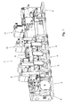
- Fig. 1 shows the printing modules 3-5 without the ink application means, the plate cylinder and the impression roller.
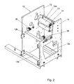
- Fig. 2 shows the main frame 12 of a printing module 3-5.
- the main frame comprises two main frame plates 12, 12', which are mutually connected by a number of rods 12a, 12b, 12c and a connecting plate 12d.
- an impression roller 13 is rotatably bearing-mounted.
- a guide roller 14 is shown, which is also bearing-mounted rotatably in the main frame 12.
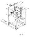
- Fig. 3 shows the printing module in a condition when it is built up somewhat further.
- a first subframe 15 is included pivotably about pivot 16.
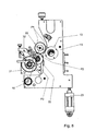
- Fig. 4 shows the first subframe 15 separately.
- the first subframe carries a motor 17 which drives a gearwheel 18.
- receiving units 20, 21 are fixedly connected with the first subframe 15, in which a plate cylinder assembly 22 (see Fig. 12 ) is receivable.
- fixation means 26, 27 are mounted, by means of which the plate cylinder assembly 22 can be fixed in the receiving units 20, 21. The construction and operation of these fixation means will be reverted to later.
- the pivoting of the first subframe 15 about the pivot 16 is effected by two piston-cylinder assemblies 23, 24.
- One end of each of these piston-cylinder assemblies 23, 24 is connected with the main frame 12, while the other end is connected with the first subframe 15.
- the pressure can be determined with which the plate cylinder 25 of the plate cylinder assembly 22 is pushed against the impression roll 13.
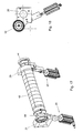
- Fig. 5 shows a sliding frame 28, 28' mounted slidably in the main frame 12.
- the sliding frame 28, 28' is provided with guide rods 29, 30 which are slidably bearing-mounted in the main frame 12.
- the sliding frame 28, 28' can be brought in an extended condition, represented in Fig. 19 .
- the sliding frame 28, 28' carries a second subframe 31, 31' which is connected with the sliding frame 28, 28' so as to be pivotable about pivot points 32, 32', which is shown in Fig. 6 .
- the sliding frame 28, 28' apart from the sliding possibility, is otherwise fixedly included in the main frame 12 and may therefore be regarded as forming part of the main frame 12. Accordingly, in the claims reference is made to a second subframe 31, 31' which is pivotably connected with the main frame 12.
- This formulation also encompasses the embodiment shown, in which the second subframe 31, 31' is pivotably connected with the sliding frame 28, 28', which may be deemed to form part of the main frame 12. It will be clear that in an embodiment that is not provided with a sliding frame 28, 28', the second subframe 31, 31' would be directly pivotably connected with the main frame 12. In the second subframe 31, 31', an anilox roller 33 and a doctor roller 34 are rotatably bearing-mounted. With the aid of piston-cylinder assemblies 35, 36, which are mounted on the main frame 12 (see also Fig. 2 ), the second subframe 31, 31' can be pressed in the direction of the plate cylinder assembly 22.
- the printing module from Fig. 6 is built up still further in that it includes a plate cylinder assembly 22. It is clearly visible that the plate cylinder assembly 22 is freely accessible at the top. To be able to utilize this freely accessible space usefully, above the receiving units 20, 21, receiving means 52, 52' are provided for mounting additional processing means.
- the receiving means comprise, in the present exemplary embodiment, two guides 52, 52'.
- the additional processing means can comprise, for instance, substrate web inverting units, winders, laminating units or the like.
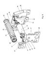
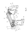
- Fig. 8 shows in side elevation the first subframe 15 which carries the plate cylinder assembly 22 and which is pivotable about pivot 16 which is pivotably connected with the main frame 12.
- the arrows P1 show the direction of movement of the plate cylinder assembly 22 as a result of a pivotal motion of the first subframe 15 about pivot 16.
- the pivotal motion is effected by the piston-cylinder assemblies 23, 24, of which in this figure only the specimen 23 is visible. With the pivotal motion, the position of the plate cylinder assembly 22 relative to the impression roller 13 disposed fixedly in the main frame 12 can be controlled.
- Fig. 8 further shows the second subframe 31 which is pivotable about pivot point 32.
- Pivoting of the second subframe 31 about pivotal point 32 results in a displacement of the anilox roller 33 in the direction of the arrows P2. With this pivotal motion, therefore, the position of the anilox roller 33 relative to the plate cylinder assembly 22 can be controlled.
- This positioning is defined in the present exemplary embodiment by a stop 37, 37', whose operation will be clarified hereinafter.
- Fig. 9 shows a perspective view of the sliding frame 28, 28' and the second subframe 31, 31' pivotably included therein, with the plate cylinder assembly 22 represented as hanging above the receiving units 20, 21. Also visible is that the anilox roller 33 is fitted in the second subframe 31, 31'.
- Arranged on the second subframe 31, 31' are two stops 37, 37'. In the present exemplary embodiment, the position of these stops 37, 37' can be set relative to the second subframe 31, 31' with the aid of adjusting screws 38, 38'.
- the stops 37, 37' form part of pivoting arms 40, 40' which are connected with the second subframe 31, 31' so as to be pivotable about a pivot 41, 41'.
- the stops 37, 37' abut against stop surfaces 39, 39' which are provided on the plate cylinder assembly 22, at least when the plate cylinder assembly 22 is received in the receiving units 20, 21, which is represented in Figs. 10 and 11 .
- the stop surfaces 39, 39' are designed as stop rings 39, 39'.
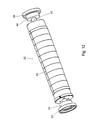
- FIG. 12 shows, in perspective, an exemplary embodiment of a plate cylinder assembly 22.
- the plate cylinder assembly 22 is provided with a plate cylinder 42 which is rotatable about a stationary shaft 43.
- Mounted on the stationary shaft 43 are the earlier-mentioned stop rings 39, 39', as well as supports 44, 44' in the form of supporting rings 44, 44' which are received in the receiving units 20, 21.
- the second subframe 31, 31' pivots about the pivot points 32, 32' and the anilox roller 33 moves relative to the plate cylinder assembly 22.
- a displacement of the plate cylinder assembly 22 will have no influence on the relative position of the plate cylinder assembly 22 and the anilox roller 33.
- the anilox roller 33 will follow displacements of the plate cylinder assembly 22 in that the stops 37, 37' are each time pressed against the plate cylinder assembly, more particularly against the stop rings 39, 39', by the piston-cylinder assemblies 35, 36.
- FIG. 13-18 To clarify how the plate cylinder assembly 22 is retained in the receiving units 20, 21, reference is made to Figs. 13-18 .
- the fixation means 26, 27 are situated substantially under the receiving units 20, 21 and the plate cylinder assembly 22, so that the space above the plate cylinder assembly 22 is freely accessible.
- the fixation means 26, 27 each comprise a piston-cylinder assembly 45, 45', which operates a rod 46, 46', which rod 46, 46' has a longitudinal centerline in the direction of which the rod 46, 46' is movable by the respective piston-cylinder assembly 45, 45'.
- the rods 46, 46' are provided with a guide slot 48, in which extends a guide lug 49 which is fixedly connected with the main frame 12.
- An upwardly directed end of each rod 46, 46' is provided with a hook 47, 47'.
- the two hooks 47, 47' engage, on opposite sides of the plate cylinder 42, the stationary shaft 43 of the plate cylinder assembly 22 when the plate cylinder assembly 22 is in the operative position.
- the piston-cylinder assemblies 45, 45' exert a pull force on the rods 46, 46', for pressing the plate cylinder assembly 22 into the receiving units 20, 21.
- the rods 46, 46' are provided with bearing surfaces 50, 50' on which rests the plate cylinder assembly 22 when the fixation means 26, 27 are in a release position.
- the plate cylinder assembly 22 in this release position is lifted out of the receiving units 20, 21 and moved upwards, such that the plate cylinder assembly 22 can be simply taken out of the printing module 3-5.
- Each bearing surface 50, 50' upon upward movement of the rods 46, 46' in the direction of the longitudinal centerlines of the rods automatically enters into engagement with the stationary shaft 43 and thereby lifts the plate cylinder assembly 22 out of the receiving units 20, 21.
- the receiving units 20, 21 are each provided with a supporting surface 51, 51', which is provided with a particular curve.
- the curve is such that the distance between plate cylinder 42 and the anilox roller 33 on the one hand and the distance between the plate cylinder 42 and the impression roller 13 on the other in each case remain, in pairs, mutually equal at different diameters of plate cylinders 42, which are provided with supports 44, 44' having diameters matching the plate cylinders 42.
- FIG. 20 it is clearly visible what is meant by this.
- the effect of such a construction of the receiving units 20, 21 and circular supporting rings 44, 44' is that when changing the plate cylinder diameter the distance between the anilox roller 33 and the plate cylinder 44 and the distance between the impression roller 13 and the plate cylinder 42 do not need to be set anew. This yields a considerable saving on the setting time.
- the plate cylinder assembly 22 may be provided with two stop surfaces whose position is settable with respect to the plate cylinder 42.
- the second subframe 31 instead of being pivotably connected with the main frame 12, or the sliding frame 28 thereof, could be pivotably connected with the first subframe 15.
- a second piston-cylinder assembly could have a first end connected with the first subframe and by a second end abut against the second subframe, such that with the aid of the second piston-cylinder assembly the second subframe is adjustable relative to the first subframe.
Landscapes
- Engineering & Computer Science (AREA)
- Mechanical Engineering (AREA)
- Rotary Presses (AREA)
- Inking, Control Or Cleaning Of Printing Machines (AREA)
- Electronic Switches (AREA)
- Dot-Matrix Printers And Others (AREA)
- Thermistors And Varistors (AREA)
Claims (23)
- Druckmodul (3-5) versehen mit einer Druckwalze (13), einer Plattenzylinder-Anordnung (22), welche einen Plattenzylinder (42) umfasst, welcher mit einem Druckbild versehen ist und welcher im Betrieb unter Einschaltung eines zu bedruckenden Trägers gegen die Druckwalze (13) stößt, einer Rasterwalze (33) und einer Auftragwalze, wobei die Auftragwalze Tinte aus einem Tintereservoir aufnimmt, wobei die Rasterwalze zwischen der Auftragwalze und dem Plattenzylinder (42) angeordnet ist, so dass eine vorbestimmte Menge an Tinte durch die Rasterwalze (33) von der Auftragwalze abgenommen und auf den Plattenzylinder (42) übertragen wird, wobei die Position des Plattenzylinders (42) einstellbar ist, wobei die Position der Rasterwalze (33) einstellbar ist und wobei die Druckwalze (13) drehbar gelagert in einem Hauptrahmen (12) montiert ist,
dadurch gekennzeichnet,
dass der Plattenzylinder (42) drehbar gelagert in einem ersten Hilfsrahmen (15) montiert ist, welcher beweglich mit dem Hauptrahmen (12) verbunden ist, um den Plattenzylinder (42) relativ zu der Druckwalze (13) zu positionieren, während die Rasterwalze (33) und die Auftragwalze in einem zweiten Hilfsrahmen (31, 31') drehbar gelagert sind, welcher beweglich mit dem Hauptrahmen (12) verbunden ist, um die Rasterwalze (33) relativ zu dem Plattenzylinder (42) zu positionieren, wobei bewegliche Verbindungen derart ausgestaltet sind, dass eine Positionsänderung des Plattenzylinders (42) relativ zu der Druckwalze (13) die Position der Rasterwalze (33) relativ zu dem Plattenzylinder (42) nicht beeinflusst und wobei eine Positionsänderung der Rasterwalze (33) relativ zu dem Plattenzylinder (42) die Position des Plattenzylinders (42) relativ zu der Druckwalze (13) nicht beeinflusst. - Druckmodul nach Anspruch 1, dadurch gekennzeichnet, dass die Plattenzylinder-Anordnung (22) mit einer Anschlagoberfläche versehen ist, und dass der zweite Hilfsrahmen (31, 31') mit einem Anschlag versehen ist, welcher im Betrieb gegen die Anschlagoberfläche des Plattenzylinders (42) stößt.
- Druckmodul nach Anspruch 2, dadurch gekennzeichnet, dass die Position des Anschlags des zweiten Hilfsrahmens (31, 31') relativ zu dem zweiten Hilfsrahmen einstellbar ist.
- Druckmodul nach Anspruch 2, dadurch gekennzeichnet, dass die Position der Anschlagoberfläche auf der Plattenzylinder-Anordnung (22) relativ zu der Plattenzylinder-Anordnung einstellbar ist.
- Druckmodul nach Anspruch 1, dadurch gekennzeichnet, dass die bewegliche Verbindung zwischen dem zweiten Hilfsrahmen (31, 31') und dem Hauptrahmen (12) durch eine bewegliche Verbindung zwischen dem zweiten Hilfsrahmen und dem ersten Hilfsrahmen realisiert ist.
- Druckmodul nach Anspruch 1, dadurch gekennzeichnet, dass die bewegliche Verbindung zwischen dem ersten Hilfsrahmen (15) und dem Hauptrahmen (12) eine Verbindung ist, welche um einen ersten Drehpunkt schwenkbar ist.
- Druckmodul nach Anspruch 5, dadurch gekennzeichnet, dass die bewegliche Verbindung zwischen dem zweiten Hilfsrahmen und dem ersten Hilfsrahmen (15) eine Verbindung ist, welche um einen zweiten Drehpunkt schwenkbar ist.
- Druckmodul nach Anspruch 1, dadurch gekennzeichnet, dass die bewegliche Verbindung zwischen dem zweiten Hilfsrahmen und dem Hauptrahmen (12) eine Verbindung ist, welche um einen zweiten Drehpunkt, welcher mit dem Hauptrahmen verbunden ist, schwenkbar ist.
- Druckmodul nach einem der vorhergehenden Ansprüche, versehen mit einer ersten Kolben-Zylinder-Anordnung, welche ein erstes Ende aufweist, welches mit dem Hauptrahmen (12) verbunden ist, und welche ein zweites Ende aufweist, welches mit dem ersten beweglichen Hilfsrahmen verbunden ist, so dass mit Hilfe der ersten Kolben-Zylinder-Anordnung der Druck, welchen der Plattenzylinder im Betrieb auf die Druckwalze ausübt, einstellbar ist.
- Druckmodul nach Anspruch 1, versehen mit einer zweiten Kolben-Zylinder-Anordnung, welche ein erstes Ende aufweist, welches mit dem Hauptrahmen (12) verbunden ist, und welche ein zweites Ende aufweist, welches mit dem zweiten Hilfsrahmen verbunden ist oder gegen diesen stößt, so dass mit Hilfe der zweiten Kolben-Zylinder-Anordnung der zweite Hilfsrahmen relativ zu dem Hauptrahmen einstellbar ist.
- Druckmodul nach Anspruch 2, versehen mit einer zweiten Kolben-Zylinder-Anordnung, welche ein erstes Ende aufweist, welches mit dem ersten Hilfsrahmen (15) verbunden ist, und welche ein zweites Ende aufweist, welches mit dem zweiten Hilfsrahmen verbunden ist oder gegen diesen stößt, so dass mit Hilfe der zweiten Kolben-Zylinder-Anordnung der zweite Hilfsrahmen relativ zu dem ersten Hilfsrahmen einstellbar ist.
- Druckmodul nach einem der vorhergehenden Ansprüche, dadurch gekennzeichnet, dass die Plattenzylinder-Anordnung (22) mit einer ortsfesten Welle versehen ist, auf welcher der Plattenzylinder drehbar gelagert montiert ist, während auf gegenüberliegenden Seiten des Plattenzylinders (42) ein Anschlagring vorhanden ist, welcher die Anschlagoberfläche ausbildet und fest mit der ortsfesten Welle verbunden ist, während auf gegenüberliegenden Seiten des Plattenzylinders ein Haltering fest mit der ortsfesten Welle verbunden ist.
- Druckmodul nach Anspruch 12, dadurch gekennzeichnet, dass der erste Hilfsrahmen (15) zwei Aufnahmeeinheiten umfasst, welche auf gegenüberliegenden Seiten des Plattenzylinders angeordnet sind, wobei Aufnahmeeinheiten die Halteringe aufnehmen, wenn die Plattenzylinder-Anordnung in der Arbeitsposition in dem Druckmodul montiert ist.
- Druckmodul nach Anspruch 13, dadurch gekennzeichnet, dass die Aufnahmeeinheiten jeweils mit einer Halteoberfläche versehen sind, welche mit einer speziellen Krümmung versehen ist, wobei die Krümmung derart ausgebildet ist, dass der Abstand zwischen dem Plattenzylinder (42) und der Rasterwalze (33) auf der einen Seite und der Abstand zwischen dem Plattenzylinder und der Druckwalze auf der anderen Seite in jedem Fall bei unterschiedlichen Durchmessern der Plattenzylinder, welche mit Halteringen eines Durchmessers versehen sind, die mit den Plattenzylindern übereinstimmen, paarweise gleich zueinander sind,
- Druckmodul nach Anspruch 13, dadurch gekennzeichnet, dass Befestigungsmittel vorhanden sind, um eine Plattenzylinder-Anordnung (22) in den Aufnahmeeinheiten zu befestigen, wobei die Befestigungsmittel im Wesentlichen unter der Plattenzylinder-Anordnung angeordnet sind.
- Druckmodul nach Anspruch 15, dadurch gekennzeichnet, dass die Befestigungsmittel zwei Stangen umfassen, welche an einem nach oben gerichteten Ende mit einem Haken versehen sind, wobei sich die zwei Haken auf gegenüberliegenden Seiten des Plattenzylinders (42) mit der ortsfesten Welle der Plattenzylinder-Anordnung (22) in Eingriff befinden, wenn sich die Plattenzylinder-Anordnung in der Arbeitsposition befindet, während auf die Stangen eine Zugkraft ausgeübt wird, um die Plattenzylinder-Anordnung in die Aufnahmeeinheiten zu drücken.
- Druckmodul nach Anspruch 16, dadurch gekennzeichnet, dass die zwei Stangen an den Enden entfernt von den Haken jeweils mit einer Kolben-Zylinder-Anordnung verbunden sind, um die Position der Stangen in einer Längsrichtung davon einzustellen und die Zugkraft auszuüben.
- Druckmodul nach einem der Ansprüche 15-17, dadurch gekennzeichnet, dass die Befestigungsmittel darüber hinaus mit Lagerungsoberflächen versehen sind, auf welchen die Plattenzylinder-Anordnung (22) ruht, wenn sich die Befestigungsmittel in einer Freigabeposition befinden, während die Plattenzylinder-Anordnung in dieser Freigabeposition aus den Aufnahmeeinheiten heraus gehoben und nach oben bewegt wird, so dass die Plattenzylinder-Anordnung (22) einfach aus dem Druckmodul genommen werden kann.
- Druckmodul nach Ansprüchen 16 und 18, dadurch gekennzeichnet, dass jede Stange mit einer Lagerungsoberfläche versehen ist, wobei die Lagerungsoberfläche bei einer nach oben gerichteten Bewegung der Stangen in der Richtung der Längsachsen der Stangen automatisch in einen Eingriff mit der ortsfesten Welle kommt und dadurch die Plattenzylinder-Anordnung (22) aus den Aufnahmeeinheiten hebt.
- Druckmodul nach Anspruch 15, dadurch gekennzeichnet, dass im Wesentlichen oberhalb der Aufnahmeeinheiten Aufnahmemittel vorhanden sind, um zusätzliche Verarbeitungsmittel anzubringen.
- Druckmodul nach Anspruch 20, dadurch gekennzeichnet, dass die Aufnahmemittel zwei Führungen umfassen.
- Druckmodul nach Anspruch 20 oder 21, dadurch gekennzeichnet, dass die zusätzlichen Verarbeitungsmittel beispielsweise Trägerbahnumdreheinheiten, Aufwickelvorrichtungen, Laminierungseinheiten oder ähnliches umfassen.
- Druckmaschine (1), welche mit einem Druckmodul nach einem der vorhergehenden Ansprüche versehen ist.
Applications Claiming Priority (3)
| Application Number | Priority Date | Filing Date | Title |
|---|---|---|---|
| NL1022048 | 2002-12-02 | ||
| NL1022048A NL1022048C2 (nl) | 2002-12-02 | 2002-12-02 | Drukmodule alsmede een drukmachine voorzien van een dergelijke drukmodule. |
| PCT/NL2003/000848 WO2004050365A1 (en) | 2002-12-02 | 2003-12-02 | Printing module, and printing machine provided with such printing module |
Publications (2)
| Publication Number | Publication Date |
|---|---|
| EP1567339A1 EP1567339A1 (de) | 2005-08-31 |
| EP1567339B1 true EP1567339B1 (de) | 2011-03-23 |
Family
ID=32464682
Family Applications (1)
| Application Number | Title | Priority Date | Filing Date |
|---|---|---|---|
| EP03779042A Expired - Lifetime EP1567339B1 (de) | 2002-12-02 | 2003-12-02 | Druckmodul und damit ausgestattete druckmaschine |
Country Status (12)
| Country | Link |
|---|---|
| US (1) | US20060117972A1 (de) |
| EP (1) | EP1567339B1 (de) |
| JP (1) | JP4361490B2 (de) |
| KR (1) | KR100865916B1 (de) |
| CN (1) | CN1735514A (de) |
| AT (1) | ATE502776T1 (de) |
| AU (1) | AU2003289675A1 (de) |
| DE (1) | DE60336500D1 (de) |
| DK (1) | DK1567339T3 (de) |
| NL (1) | NL1022048C2 (de) |
| TW (1) | TWI313642B (de) |
| WO (1) | WO2004050365A1 (de) |
Families Citing this family (15)
| Publication number | Priority date | Publication date | Assignee | Title |
|---|---|---|---|---|
| NL1022049C2 (nl) * | 2002-12-02 | 2004-06-11 | Mps Holding B V | Drukmodule alsmede een drukmachine voorzien van een dergelijke drukmodule. |
| NL1026736C2 (nl) | 2004-07-28 | 2006-01-31 | Stork Prints Bv | Drukcilinderondersteuningseenheid, positioneerelement, drukcilinder voorzien van positioneerelement, drukmachine voorzien van drukcilinderondersteuningseenheid, en gebruik hiervan. |
| KR100679461B1 (ko) * | 2006-04-04 | 2007-02-06 | 주식회사지엠피 | 라미네이터가 형성된 인쇄장치 |
| KR100882136B1 (ko) * | 2008-06-05 | 2009-02-06 | 주식회사 파코엔지니어링 | 강판용 연속 인쇄기 |
| FR2954213B1 (fr) * | 2009-12-21 | 2012-03-09 | Sleever Int | Machine d'impression en continu d'une bande par flexographie |
| KR101001667B1 (ko) | 2010-09-07 | 2010-12-15 | 우진기계 주식회사 | 강판 인쇄기용 닥터 블레이드 조정장치 |
| CN103909723B (zh) * | 2014-03-31 | 2015-10-07 | 浙江方邦机械有限公司 | 机组式柔印机精准套印机构 |
| CN106687292B (zh) * | 2014-09-17 | 2019-03-08 | 小森公司 | 凹版印刷机的擦拭辊的接触压力的调整方法及装置 |
| CN105643923B (zh) * | 2014-11-13 | 2018-04-24 | 三纬国际立体列印科技股份有限公司 | 立体打印装置 |
| CN106113906A (zh) * | 2016-06-30 | 2016-11-16 | 苏州华尔美特装饰材料股份有限公司 | 一种滚筒印花装置 |
| NL2019408B1 (nl) * | 2017-08-10 | 2019-02-21 | Mps Holding Bv | Samenstel voor het bewerken van een substraatbaan |
| USD870203S1 (en) * | 2018-03-08 | 2019-12-17 | Koenig & Bauer Ag | Printing machine |
| CN110978767B (zh) * | 2019-11-27 | 2024-05-07 | 东莞市源铁印刷机械有限公司 | 一种柔版印刷机组 |
| USD943666S1 (en) * | 2020-06-09 | 2022-02-15 | Bobst Bielefeld Gmbh | Printing machine |
| CN111619204B (zh) * | 2020-06-30 | 2024-05-17 | 深圳弘博智能数码设备有限公司 | 版辊安装模组及印刷设备 |
Family Cites Families (32)
| Publication number | Priority date | Publication date | Assignee | Title |
|---|---|---|---|---|
| US3453955A (en) * | 1965-10-20 | 1969-07-08 | Harris Intertype Corp | Shock absorber with movement limiting stop for rotary printing press cylinders |
| GB1349753A (en) * | 1970-04-27 | 1974-04-10 | Odhams Watford Ltd | Printing press |
| US3774535A (en) * | 1971-04-12 | 1973-11-27 | Njm Inc Hoboken | System of and apparatus for printing business forms |
| US4222325A (en) * | 1978-08-25 | 1980-09-16 | White Consolidated Industries, Inc. | Mounting means for movable carriage on an offset press |
| US4879950A (en) * | 1987-06-19 | 1989-11-14 | Ryobi Ltd. | Image position adjusting apparatus of rotary press machine |
| US4878427A (en) | 1987-07-21 | 1989-11-07 | Webtron Corporation | Printing station with toolless changeable plate cylinder |
| DE3915481A1 (de) * | 1989-05-11 | 1990-12-13 | Windmoeller & Hoelscher | Vorrichtung zum anstellen und abheben eines auf einen formzylinder wirkenden gegendruckzylinders |
| DE3926087C1 (de) * | 1989-08-07 | 1990-10-04 | Heidelberger Druckmaschinen Ag, 6900 Heidelberg, De | |
| DE4003412A1 (de) * | 1990-02-05 | 1991-08-08 | Koenig & Bauer Ag | Buerstenfeuchtwerk |
| DK172047B1 (da) * | 1993-02-03 | 1997-09-29 | Leoprint Maschinen Gmbh | Anordninger til indstilling af akseafstande mellem cylindre i et trykkeværk |
| US5301609A (en) * | 1993-03-04 | 1994-04-12 | Heidelberg Harris Inc. | Printing unit with skew and throw-off mechanisms |
| DE4413807C1 (de) * | 1994-04-20 | 1995-09-14 | Windmoeller & Hoelscher | Vorrichtung zum Wechseln der Zylinder an einer Druckmaschine |
| EP0736330A3 (de) * | 1995-04-07 | 1997-07-09 | Ltg Lufttechnische Gmbh | Lackiermaschine |
| DE19515847C1 (de) * | 1995-04-29 | 1996-07-18 | Heidelberger Druckmasch Ag | Steuervorrichtung für ein Numerier- und Eindruckwerk von Rotationsdruckmaschinen |
| US6435086B1 (en) * | 1995-05-04 | 2002-08-20 | Howard W. DeMoore | Retractable inking/coating apparatus having ferris movement between printing units |
| JP2864224B2 (ja) * | 1995-06-30 | 1999-03-03 | 株式会社東京機械製作所 | インキ供給装置 |
| US5678485A (en) * | 1995-12-22 | 1997-10-21 | Heidelberger Druckmaschinen Ag | Counterpoise and lift mechanism |
| US5746132A (en) * | 1996-09-24 | 1998-05-05 | Mark Andy, Inc. | Variable repeat plate and blanket cylinder mechanism |
| US6077020A (en) * | 1996-10-15 | 2000-06-20 | Haul-All Equipment Ltd. | Garbage or recyclable materials handling system |
| AU8291998A (en) * | 1997-07-09 | 1999-02-08 | Langston Corporation, The | Apparatus for printing corrugated board |
| IL121564A (en) * | 1997-08-18 | 2001-06-14 | Scitex Corp Ltd | Double-sided printing press with a single printing roller for each color |
| US6006665A (en) * | 1997-10-30 | 1999-12-28 | Didde Web Press Corporation | Pliable anilox roller |
| US6041709A (en) * | 1998-11-12 | 2000-03-28 | Usadvantage, Inc. | Peristaltic pump for pumping ink or cleaning fluids in a printing machine |
| US6272986B1 (en) * | 1999-10-15 | 2001-08-14 | Howard W. DeMoore | Retractable impression cylinder inking/coating apparatus having ferris movement between printing units |
| NL1013620C2 (nl) * | 1999-11-19 | 2001-05-22 | Drent Holding B V | Inrichting voor het verwisselbaar opnemen en positioneren van de drukcilinders van een offset drukpers. |
| DE19960012C1 (de) * | 1999-12-13 | 2001-02-15 | Cts Fahrzeug Dachsysteme Gmbh | Vorrichtung zur Verriegelung zweier relativ zueineander verstellbarer, zwangsgeführter Elemente |
| JP2003103759A (ja) * | 2001-10-01 | 2003-04-09 | Lintec Corp | 印刷装置におけるロール支持構造 |
| JP4361720B2 (ja) * | 2002-08-20 | 2009-11-11 | 株式会社小森コーポレーション | 版交換装置 |
| US7048214B2 (en) * | 2002-08-23 | 2006-05-23 | Louis Wein Johnson | Gyratory crusher with hydrostatic bearings |
| JP4163923B2 (ja) * | 2002-10-01 | 2008-10-08 | 株式会社小森コーポレーション | 凹版印刷機 |
| US6796228B2 (en) * | 2002-12-27 | 2004-09-28 | Day International, Inc. | Dampener metering device |
| US6907823B2 (en) * | 2003-10-21 | 2005-06-21 | Creo Inc. | Flexographic printing on containers |
-
2002
- 2002-12-02 NL NL1022048A patent/NL1022048C2/nl not_active IP Right Cessation
-
2003
- 2003-12-02 DE DE60336500T patent/DE60336500D1/de not_active Expired - Lifetime
- 2003-12-02 DK DK03779042.5T patent/DK1567339T3/da active
- 2003-12-02 EP EP03779042A patent/EP1567339B1/de not_active Expired - Lifetime
- 2003-12-02 KR KR1020057010035A patent/KR100865916B1/ko not_active Expired - Fee Related
- 2003-12-02 US US10/537,099 patent/US20060117972A1/en not_active Abandoned
- 2003-12-02 AT AT03779042T patent/ATE502776T1/de not_active IP Right Cessation
- 2003-12-02 AU AU2003289675A patent/AU2003289675A1/en not_active Abandoned
- 2003-12-02 CN CNA200380108255XA patent/CN1735514A/zh active Pending
- 2003-12-02 TW TW092133805A patent/TWI313642B/zh active
- 2003-12-02 JP JP2004556987A patent/JP4361490B2/ja not_active Expired - Fee Related
- 2003-12-02 WO PCT/NL2003/000848 patent/WO2004050365A1/en not_active Ceased
Also Published As
| Publication number | Publication date |
|---|---|
| TWI313642B (en) | 2009-08-21 |
| DK1567339T3 (da) | 2011-06-20 |
| ATE502776T1 (de) | 2011-04-15 |
| DE60336500D1 (de) | 2011-05-05 |
| WO2004050365A1 (en) | 2004-06-17 |
| NL1022048C2 (nl) | 2004-06-03 |
| CN1735514A (zh) | 2006-02-15 |
| AU2003289675A1 (en) | 2004-06-23 |
| KR100865916B1 (ko) | 2008-10-29 |
| US20060117972A1 (en) | 2006-06-08 |
| JP2006507956A (ja) | 2006-03-09 |
| KR20050084123A (ko) | 2005-08-26 |
| JP4361490B2 (ja) | 2009-11-11 |
| TW200415026A (en) | 2004-08-16 |
| EP1567339A1 (de) | 2005-08-31 |
Similar Documents
| Publication | Publication Date | Title |
|---|---|---|
| EP1567339B1 (de) | Druckmodul und damit ausgestattete druckmaschine | |
| US6694877B1 (en) | Device for exchangeably supporting and positioning printing cylinders of an offset printing press | |
| RU2066277C1 (ru) | Рулонное печатное устройство | |
| JP2918075B2 (ja) | 高速版板交換を行うことのできる印刷装置 | |
| US9586393B2 (en) | Rotary printing module and printing machine provided with such printing module | |
| US8850975B2 (en) | Impression mechanism for a variable cutoff printing unit | |
| EP1285753B1 (de) | Druckvorrichtung, insbesondere flexographische Druckmaschine | |
| EP1567340B1 (de) | Druckmodul und damit ausgestattete druckmaschine | |
| US5009159A (en) | Printing unit | |
| CN219883482U (zh) | 一种套筒式柔版印刷机可调装置 | |
| JP2921656B2 (ja) | 輪転印刷機のための枚葉紙引き渡し胴 | |
| CN220314457U (zh) | 一种印刷辊压机构 | |
| EP2465679A1 (de) | Einstellbare Farb-oder- Feuchtmittelzuführvorrichtung für Druckpresse mit einstellbarer Drucklänge, sowie Verfahren | |
| CN216885773U (zh) | 一种转印辊驱动结构及印刷设备 | |
| CN219927215U (zh) | 一种柔版印刷机印刷压力调整装置 | |
| CN221318481U (zh) | 一种印刷机的输送装置 | |
| CN116476510A (zh) | 一种柔性印刷设备及其印刷方法 |
Legal Events
| Date | Code | Title | Description |
|---|---|---|---|
| PUAI | Public reference made under article 153(3) epc to a published international application that has entered the european phase |
Free format text: ORIGINAL CODE: 0009012 |
|
| 17P | Request for examination filed |
Effective date: 20050617 |
|
| AK | Designated contracting states |
Kind code of ref document: A1 Designated state(s): AT BE BG CH CY CZ DE DK EE ES FI FR GB GR HU IE IT LI LU MC NL PT RO SE SI SK |
|
| AX | Request for extension of the european patent |
Extension state: AL LT LV MK |
|
| DAX | Request for extension of the european patent (deleted) | ||
| GRAP | Despatch of communication of intention to grant a patent |
Free format text: ORIGINAL CODE: EPIDOSNIGR1 |
|
| GRAS | Grant fee paid |
Free format text: ORIGINAL CODE: EPIDOSNIGR3 |
|
| GRAA | (expected) grant |
Free format text: ORIGINAL CODE: 0009210 |
|
| AK | Designated contracting states |
Kind code of ref document: B1 Designated state(s): AT BE BG CH CY CZ DE DK EE ES FI FR GB GR HU IE IT LI LU MC NL PT RO SE SI SK |
|
| REG | Reference to a national code |
Ref country code: GB Ref legal event code: FG4D |
|
| REG | Reference to a national code |
Ref country code: CH Ref legal event code: EP |
|
| REG | Reference to a national code |
Ref country code: IE Ref legal event code: FG4D |
|
| REF | Corresponds to: |
Ref document number: 60336500 Country of ref document: DE Date of ref document: 20110505 Kind code of ref document: P |
|
| REG | Reference to a national code |
Ref country code: DE Ref legal event code: R096 Ref document number: 60336500 Country of ref document: DE Effective date: 20110505 |
|
| REG | Reference to a national code |
Ref country code: CH Ref legal event code: NV Representative=s name: E. BLUM & CO. AG PATENT- UND MARKENANWAELTE VSP |
|
| REG | Reference to a national code |
Ref country code: DK Ref legal event code: T3 |
|
| REG | Reference to a national code |
Ref country code: NL Ref legal event code: T3 |
|
| PG25 | Lapsed in a contracting state [announced via postgrant information from national office to epo] |
Ref country code: SE Free format text: LAPSE BECAUSE OF FAILURE TO SUBMIT A TRANSLATION OF THE DESCRIPTION OR TO PAY THE FEE WITHIN THE PRESCRIBED TIME-LIMIT Effective date: 20110323 Ref country code: GR Free format text: LAPSE BECAUSE OF FAILURE TO SUBMIT A TRANSLATION OF THE DESCRIPTION OR TO PAY THE FEE WITHIN THE PRESCRIBED TIME-LIMIT Effective date: 20110624 |
|
| PG25 | Lapsed in a contracting state [announced via postgrant information from national office to epo] |
Ref country code: BG Free format text: LAPSE BECAUSE OF FAILURE TO SUBMIT A TRANSLATION OF THE DESCRIPTION OR TO PAY THE FEE WITHIN THE PRESCRIBED TIME-LIMIT Effective date: 20110623 Ref country code: AT Free format text: LAPSE BECAUSE OF FAILURE TO SUBMIT A TRANSLATION OF THE DESCRIPTION OR TO PAY THE FEE WITHIN THE PRESCRIBED TIME-LIMIT Effective date: 20110323 Ref country code: CY Free format text: LAPSE BECAUSE OF FAILURE TO SUBMIT A TRANSLATION OF THE DESCRIPTION OR TO PAY THE FEE WITHIN THE PRESCRIBED TIME-LIMIT Effective date: 20110323 Ref country code: SI Free format text: LAPSE BECAUSE OF FAILURE TO SUBMIT A TRANSLATION OF THE DESCRIPTION OR TO PAY THE FEE WITHIN THE PRESCRIBED TIME-LIMIT Effective date: 20110323 Ref country code: FI Free format text: LAPSE BECAUSE OF FAILURE TO SUBMIT A TRANSLATION OF THE DESCRIPTION OR TO PAY THE FEE WITHIN THE PRESCRIBED TIME-LIMIT Effective date: 20110323 |
|
| PG25 | Lapsed in a contracting state [announced via postgrant information from national office to epo] |
Ref country code: BE Free format text: LAPSE BECAUSE OF FAILURE TO SUBMIT A TRANSLATION OF THE DESCRIPTION OR TO PAY THE FEE WITHIN THE PRESCRIBED TIME-LIMIT Effective date: 20110323 |
|
| PG25 | Lapsed in a contracting state [announced via postgrant information from national office to epo] |
Ref country code: EE Free format text: LAPSE BECAUSE OF FAILURE TO SUBMIT A TRANSLATION OF THE DESCRIPTION OR TO PAY THE FEE WITHIN THE PRESCRIBED TIME-LIMIT Effective date: 20110323 Ref country code: PT Free format text: LAPSE BECAUSE OF FAILURE TO SUBMIT A TRANSLATION OF THE DESCRIPTION OR TO PAY THE FEE WITHIN THE PRESCRIBED TIME-LIMIT Effective date: 20110725 |
|
| PG25 | Lapsed in a contracting state [announced via postgrant information from national office to epo] |
Ref country code: RO Free format text: LAPSE BECAUSE OF FAILURE TO SUBMIT A TRANSLATION OF THE DESCRIPTION OR TO PAY THE FEE WITHIN THE PRESCRIBED TIME-LIMIT Effective date: 20110323 Ref country code: ES Free format text: LAPSE BECAUSE OF FAILURE TO SUBMIT A TRANSLATION OF THE DESCRIPTION OR TO PAY THE FEE WITHIN THE PRESCRIBED TIME-LIMIT Effective date: 20110704 Ref country code: SK Free format text: LAPSE BECAUSE OF FAILURE TO SUBMIT A TRANSLATION OF THE DESCRIPTION OR TO PAY THE FEE WITHIN THE PRESCRIBED TIME-LIMIT Effective date: 20110323 Ref country code: CZ Free format text: LAPSE BECAUSE OF FAILURE TO SUBMIT A TRANSLATION OF THE DESCRIPTION OR TO PAY THE FEE WITHIN THE PRESCRIBED TIME-LIMIT Effective date: 20110323 |
|
| PLBE | No opposition filed within time limit |
Free format text: ORIGINAL CODE: 0009261 |
|
| STAA | Information on the status of an ep patent application or granted ep patent |
Free format text: STATUS: NO OPPOSITION FILED WITHIN TIME LIMIT |
|
| 26N | No opposition filed |
Effective date: 20111227 |
|
| REG | Reference to a national code |
Ref country code: DE Ref legal event code: R097 Ref document number: 60336500 Country of ref document: DE Effective date: 20111227 |
|
| PG25 | Lapsed in a contracting state [announced via postgrant information from national office to epo] |
Ref country code: MC Free format text: LAPSE BECAUSE OF NON-PAYMENT OF DUE FEES Effective date: 20111231 |
|
| REG | Reference to a national code |
Ref country code: IE Ref legal event code: MM4A |
|
| PG25 | Lapsed in a contracting state [announced via postgrant information from national office to epo] |
Ref country code: IE Free format text: LAPSE BECAUSE OF NON-PAYMENT OF DUE FEES Effective date: 20111202 |
|
| PG25 | Lapsed in a contracting state [announced via postgrant information from national office to epo] |
Ref country code: LU Free format text: LAPSE BECAUSE OF NON-PAYMENT OF DUE FEES Effective date: 20111202 |
|
| PG25 | Lapsed in a contracting state [announced via postgrant information from national office to epo] |
Ref country code: HU Free format text: LAPSE BECAUSE OF FAILURE TO SUBMIT A TRANSLATION OF THE DESCRIPTION OR TO PAY THE FEE WITHIN THE PRESCRIBED TIME-LIMIT Effective date: 20110323 |
|
| REG | Reference to a national code |
Ref country code: FR Ref legal event code: PLFP Year of fee payment: 13 |
|
| REG | Reference to a national code |
Ref country code: FR Ref legal event code: PLFP Year of fee payment: 14 |
|
| REG | Reference to a national code |
Ref country code: FR Ref legal event code: PLFP Year of fee payment: 15 |
|
| PGFP | Annual fee paid to national office [announced via postgrant information from national office to epo] |
Ref country code: NL Payment date: 20201124 Year of fee payment: 18 |
|
| PGFP | Annual fee paid to national office [announced via postgrant information from national office to epo] |
Ref country code: FR Payment date: 20201223 Year of fee payment: 18 Ref country code: GB Payment date: 20201223 Year of fee payment: 18 Ref country code: DK Payment date: 20201223 Year of fee payment: 18 Ref country code: DE Payment date: 20201211 Year of fee payment: 18 Ref country code: CH Payment date: 20201221 Year of fee payment: 18 |
|
| PGFP | Annual fee paid to national office [announced via postgrant information from national office to epo] |
Ref country code: IT Payment date: 20201224 Year of fee payment: 18 |
|
| REG | Reference to a national code |
Ref country code: DE Ref legal event code: R119 Ref document number: 60336500 Country of ref document: DE |
|
| REG | Reference to a national code |
Ref country code: DK Ref legal event code: EBP Effective date: 20211231 |
|
| REG | Reference to a national code |
Ref country code: CH Ref legal event code: PL |
|
| REG | Reference to a national code |
Ref country code: NL Ref legal event code: MM Effective date: 20220101 |
|
| GBPC | Gb: european patent ceased through non-payment of renewal fee |
Effective date: 20211202 |
|
| PG25 | Lapsed in a contracting state [announced via postgrant information from national office to epo] |
Ref country code: NL Free format text: LAPSE BECAUSE OF NON-PAYMENT OF DUE FEES Effective date: 20220101 |
|
| PG25 | Lapsed in a contracting state [announced via postgrant information from national office to epo] |
Ref country code: GB Free format text: LAPSE BECAUSE OF NON-PAYMENT OF DUE FEES Effective date: 20211202 Ref country code: DE Free format text: LAPSE BECAUSE OF NON-PAYMENT OF DUE FEES Effective date: 20220701 |
|
| PG25 | Lapsed in a contracting state [announced via postgrant information from national office to epo] |
Ref country code: FR Free format text: LAPSE BECAUSE OF NON-PAYMENT OF DUE FEES Effective date: 20211231 |
|
| PG25 | Lapsed in a contracting state [announced via postgrant information from national office to epo] |
Ref country code: LI Free format text: LAPSE BECAUSE OF NON-PAYMENT OF DUE FEES Effective date: 20211231 Ref country code: CH Free format text: LAPSE BECAUSE OF NON-PAYMENT OF DUE FEES Effective date: 20211231 |
|
| PG25 | Lapsed in a contracting state [announced via postgrant information from national office to epo] |
Ref country code: IT Free format text: LAPSE BECAUSE OF NON-PAYMENT OF DUE FEES Effective date: 20211202 Ref country code: DK Free format text: LAPSE BECAUSE OF NON-PAYMENT OF DUE FEES Effective date: 20211231 |