EP1567323B1 - Tambour a ceinture et a bande de roulement - Google Patents
Tambour a ceinture et a bande de roulement Download PDFInfo
- Publication number
- EP1567323B1 EP1567323B1 EP03774390A EP03774390A EP1567323B1 EP 1567323 B1 EP1567323 B1 EP 1567323B1 EP 03774390 A EP03774390 A EP 03774390A EP 03774390 A EP03774390 A EP 03774390A EP 1567323 B1 EP1567323 B1 EP 1567323B1
- Authority
- EP
- European Patent Office
- Prior art keywords
- drum
- belt
- magnets
- tread
- support
- Prior art date
- Legal status (The legal status is an assumption and is not a legal conclusion. Google has not performed a legal analysis and makes no representation as to the accuracy of the status listed.)
- Expired - Lifetime
Links
Images

Classifications
-
- B—PERFORMING OPERATIONS; TRANSPORTING
- B29—WORKING OF PLASTICS; WORKING OF SUBSTANCES IN A PLASTIC STATE IN GENERAL
- B29D—PRODUCING PARTICULAR ARTICLES FROM PLASTICS OR FROM SUBSTANCES IN A PLASTIC STATE
- B29D30/00—Producing pneumatic or solid tyres or parts thereof
- B29D30/06—Pneumatic tyres or parts thereof (e.g. produced by casting, moulding, compression moulding, injection moulding, centrifugal casting)
- B29D30/08—Building tyres
- B29D30/20—Building tyres by the flat-tyre method, i.e. building on cylindrical drums
- B29D30/24—Drums
-
- B—PERFORMING OPERATIONS; TRANSPORTING
- B29—WORKING OF PLASTICS; WORKING OF SUBSTANCES IN A PLASTIC STATE IN GENERAL
- B29D—PRODUCING PARTICULAR ARTICLES FROM PLASTICS OR FROM SUBSTANCES IN A PLASTIC STATE
- B29D30/00—Producing pneumatic or solid tyres or parts thereof
- B29D30/06—Pneumatic tyres or parts thereof (e.g. produced by casting, moulding, compression moulding, injection moulding, centrifugal casting)
- B29D30/08—Building tyres
- B29D30/20—Building tyres by the flat-tyre method, i.e. building on cylindrical drums
- B29D30/24—Drums
- B29D30/242—Drums for manufacturing substantially cylindrical tyre components without cores or beads, e.g. treads or belts
-
- B—PERFORMING OPERATIONS; TRANSPORTING
- B29—WORKING OF PLASTICS; WORKING OF SUBSTANCES IN A PLASTIC STATE IN GENERAL
- B29D—PRODUCING PARTICULAR ARTICLES FROM PLASTICS OR FROM SUBSTANCES IN A PLASTIC STATE
- B29D30/00—Producing pneumatic or solid tyres or parts thereof
- B29D30/06—Pneumatic tyres or parts thereof (e.g. produced by casting, moulding, compression moulding, injection moulding, centrifugal casting)
- B29D30/08—Building tyres
- B29D30/20—Building tyres by the flat-tyre method, i.e. building on cylindrical drums
- B29D30/24—Drums
- B29D30/26—Accessories or details, e.g. membranes, transfer rings
- B29D2030/2671—Holding the layers, e.g. the webs or the plies, in position onto the drum
- B29D2030/2678—Holding the layers, e.g. the webs or the plies, in position onto the drum by using magnets
Definitions
- the invention relates to a belt and tread drum.
- the invention particularly relates to a drum on which a belt layer and a tread layer can be arranged to be shaped into a circumferential whole.
- belt and tread drums that are provided with magnets in order to retain the tyre component on the drum surface by magnetic influence on the metal parts, such as steel wires, incorporated in said tyre component arranged on the drum.
- the drum surface is defined by a series of parallel, elongated support members that are each provided with a number of magnets.
- the support members are separately attached on the drum and at the radial outside provided with elongated recesses, in which the magnets are accommodated with the intermediary of a tray-shaped steel holder.
- the magnet is glued in the holder and the holder is glued in the recess.
- the invention provides a belt and tread drum, particularly for shaping a belt layer and/or tread layer or another tyre component provided with metal parts into a circumferential whole, comprising one or more support members arranged at the circumference of the drum, which are provided with a support surface for the tyre component, wherein the support members comprise magnet sets having magnets for by magnetically attracting the metal parts retaining the tyre component on the support surface, wherein the magnet sets comprise holders for the magnets and are placed from the radial inside in the support members, wherein the drum at the circumferential side comprises first portions that engage over the holders in tangential and/or axial direction of the drum, wherein the drum at the circumferential side comprises second portions that engage over the magnets in tangential and/or axial direction of the drum.
- the magnet sets are arranged in the support members from the inner side that is opposite the support surface. As a result the magnets are stopped in radial outward direction so that they cannot inadvertently get detached from the drum.
- the preferably tray-shaped holders are thus also stopped radially to the outside in a simple and reliable manner.
- first portions and/or second portions of the drum are part of the support surfaces, so that a simple structure is achieved.
- the first portions or the support surfaces extend over the entire surface of the magnets. This does not only result in a further simplified structure, but the support surface is question also provides a support surface that continues over the magnets.
- the support surfaces are formed as one unity with the support members.
- the second portions may, alternatively or additionally to the support surfaces formed by support members, be formed by the holders.
- first and/or second portions of the drum form inclined wedge planes, that cooperate with complementary wedge planes that are formed on the magnet holders and/or magnets, respectively.
- the wedge planes offer a simple and reliable confinement in radial outward direction and have a directional component that is radially oriented to the inside.
- the holders are manufactured of steel, due to which the effectiveness of the magnets is enhanced.
- a belt and tread drum particularly for shaping a belt layer and/or tread layer or another tyre component provided with metal parts into a circumferential whole, comprising one or more support members arranged at the circumference of the drum, which are provided with a support surface for the tyre component, wherein the support members are provided with magnet sets having magnets for by magnetically attracting the metal parts retaining the tyre component on the support surface and with holders for the magnets, wherein the drum at the outer side comprises confining portions that form a unity with the support members, which confining portions confine the magnets and/or the holders in radial outward direction of the drum.
- the holders themselves can also form such confining portions that engage over the magnets in tangential and/or axial direction of the drum.
- the holders can be secured in the support members by means of glue applied from the radial inside.
- the confining portions are formed by wedge planes that cooperate with wedge planes on the magnets and/or the holders.
- the operator can easily see -even with the said continuous support surface- where the magnets are located in the drum and correctly arrange the tyre components.
- a belt and tread drum particularly for shaping a belt layer and/or tread layer or another tyre component provided with metal parts into a circumferential whole, comprising one or more support members arranged at the circumference of the drum, which are provided with a support surface for the tyre component, wherein magnets are accommodated in the support members for by magnetically attracting the metal parts retaining the tyre component on the support surface, wherein the support members comprise portions that are formed as one unity with it that engage over the magnets in tangential and/or axial direction of the drum.
- the magnets are accommodated in holders that are placed from the radial inside in the support members, wherein the support members at the circumferential side comprise portions that engage over the holders and/or over the magnets in tangential and/or axial direction of the drum.
- the said portions are also part of the support surfaces.
- the invention furthermore provides a support member intended and suitable for use in a belt and tread drum according to the invention.
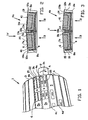
- the belt and tread drum 1 shown in part in figure 1 has a support/drive shaft 2, which with means that are not further shown can be rotated very fast in the direction A.
- the drum surface 3 consists of segments, namely support members 4, in which magnets are accommodated. During the fast rotation of the drum 1, said magnets are able to retain tyre components (not shown) that have been arranged on the drum surface 3. This is known per se.
- the support members 4 are detachably attached to the drum 1.
- the support member 4a of figure 2 comprises an aluminium body 5a, which at the upper side as considered in the drawing, that is the radial outside of the drum, defines a closed surface. From the side B recesses formed in the aluminium body 5a are accessible, which recesses in fact form blind holes 40. In said recesses 40 a pair of steel trays 8a are accommodated, in which magnets 7a are attached with glue. The upper surface 6 of the magnets 7a is aligned with the upper surface of the tray 8a in question. A support surface 11 a forming a unity with the aluminium body 5a extends over it. It can be seen that the magnets 7a and the trays 8a are confined to the outside by the aluminium material due to the aluminium thus continuing over them.
- the trays 8a are fitted within steps 18a, 19a in the aluminium body 5a.
- a glue layer 9 is applied to secure the trays 8a in the aluminium body 5a, wherein the glue may extend up to the surfaces 12a, 13a of the steps 18a, 19a.
- the support member 4a is shown with holes 22 for mounting on the drum 3, and with holes 21 by which means an additional series of support members 4a can be attached on the already present support members 4a and can be removed from them again, if an increase/reduction of the diameter of the drum 3 is desired.
- the aluminium body 5b does not form blind holes, but through-holes. Holes are now limited at the location of the outer surface by shoulders 18b, 19b, that are provided with inclined planes 14, which inclined planes are able to cooperate with inclined planes 15 formed at the edges of the trays 8b.
- the trays 8b themselves are provided with slightly tapering walls 30, in between which the magnets 7b, shaped correspondingly inclined, have been inserted in longitudinal direction. The magnets 7b are thus stopped radially to the outside by wedge action, and the holders 8b are also stopped radially to the outside due to contact between the inclined planes 14 and 15.
- the holders 8b with magnets 7b are inserted into the aluminium body 5b from the inside in the direction B, and subsequently secured with glue 9.
- a support member 4b as shown in figure 5 is for instance thus achieved, which in the same manner as support member 4a can be secured on the drum 1.
- the surface 6 of the magnet 7b will extend into the surface of the aluminium body 5b. No marking is necessary then, as can be seen in figure 1.
- figure 2 can be supplemented by the way of confining a magnet according to figure 3.
- the aluminium body itself forms a wedge-shaped confinement for the magnets, and a step or wedge plane for the confinement of the holders for the magnets.
- support members 4c and 4d comparable to support member 4a can be arranged on the drum 1, wherein the location of the magnets is shifted in shaft direction.
- This arrangement has to do with the diamond shape of the tyre components, wherein there is question of a tapering leading end and a tapering trailing end. By means of the markings 20 the operator is able to correctly position the tapering leading end.
Landscapes
- Engineering & Computer Science (AREA)
- Mechanical Engineering (AREA)
- Manufacturing & Machinery (AREA)
- Tyre Moulding (AREA)
- Tires In General (AREA)
- Absorbent Articles And Supports Therefor (AREA)
- Polishing Bodies And Polishing Tools (AREA)
- Paper (AREA)
Claims (12)
- Tambour à ceinture et à bande de roulement (1), en particulier pour la mise en forme d'un ensemble circonférentiel d'une couche de ceinture et/ou d'une couche de bande de roulement ou d'un autre composant de bandage muni de parties métalliques, comportant un ou plusieurs éléments de support (4a, 4b, 4c, 4d) agencés à la circonférence du tambour, qui sont munis d'une surface de support du composant de bandage,
dans lequel les éléments de support (4a, 4b, 4c, 4d) comportent des ensembles d'aimants ayant des aimants (7a, 7b) pour retenir le composant de bandage sur la surface de support en attirant magnétiquement les parties métalliques, dans lequel les ensembles d'aimants comportent des supports (8a, 8b) pour les aimants (7a, 7b),
dans lequel le tambour, au niveau du côté circonférentiel, comporte des premières parties qui viennent en prise au-dessus des supports (8a, 8b) dans une direction tangentielle et/ou axiale du tambour,
dans lequel le tambour, au niveau du côté circonférentiel, comporte des secondes parties qui viennent en prise au-dessus des aimants (7a, 7b) dans une direction tangentielle et/ou axiale du tambour, le tambour étant caractérisé en ce que :lesdits éléments de support (4a, 4b, 4c, 4d) sont configurés d'une manière telle que les ensembles d'aimants sont placés depuis l'intérieur radial dans les éléments de support (4a, 4b, 4c, 4d). - Tambour à ceinture et à bande de roulement selon la revendication 1, dans lequel les premières parties du tambour sont une partie des surfaces de support.
- Tambour à ceinture et à bande de roulement selon la revendication 2, dans lequel les secondes parties du tambour sont une partie des surfaces de support.
- Tambour à ceinture et à bande de roulement selon la revendication 3, dans lequel les surfaces de support s'étendent sur toute la surface des aimants.
- Tambour à ceinture et à bande de roulement selon la revendication 1, 2 ou 3, dans lequel les aimants sont une partie des surfaces de support.
- Tambour à ceinture et à bande de roulement selon l'une quelconque des revendications précédentes, dans lequel les surfaces de support sont formées comme une unité avec les éléments de support.
- Tambour à ceinture et à bande de roulement selon l'une quelconque des revendications précédentes, dans lequel les secondes parties du tambour sont formées par les supports.
- Tambour à ceinture et à bande de roulement selon l'une quelconque des revendications précédentes, dans lequel les premières et/ou secondes parties du tambour forment des plans de cale inclinés, qui coopèrent avec des plans de cale complémentaires qui sont formés sur les supports d'aimants et/ou sur les aimants, respectivement.
- Tambour à ceinture et à bande de roulement selon l'une quelconque des revendications précédentes, dans lequel les supports sont en forme de plateau.
- Tambour à ceinture et à bande de roulement selon l'une quelconque des revendications précédentes, dans lequel les supports sont fabriqués en acier.
- Tambour à ceinture et à bande de roulement selon l'une quelconque des revendications précédentes, dans lequel les surfaces de support à l'emplacement des aimants sont munies d'un repère.
- Élément de support (4a, 4b, 4c, 4d) prévu et adapté pour être utilisé dans un tambour à ceinture et à bande de roulement (1) selon l'une quelconque des revendications précédentes.
Applications Claiming Priority (3)
| Application Number | Priority Date | Filing Date | Title |
|---|---|---|---|
| NL1021958A NL1021958C2 (nl) | 2002-11-20 | 2002-11-20 | Gordel- en loopvlaktrommel. |
| NL1021958 | 2002-11-20 | ||
| PCT/NL2003/000814 WO2004045839A1 (fr) | 2002-11-20 | 2003-11-19 | Tambour a ceinture et a bande de roulement |
Publications (2)
| Publication Number | Publication Date |
|---|---|
| EP1567323A1 EP1567323A1 (fr) | 2005-08-31 |
| EP1567323B1 true EP1567323B1 (fr) | 2006-07-12 |
Family
ID=30439556
Family Applications (1)
| Application Number | Title | Priority Date | Filing Date |
|---|---|---|---|
| EP03774390A Expired - Lifetime EP1567323B1 (fr) | 2002-11-20 | 2003-11-19 | Tambour a ceinture et a bande de roulement |
Country Status (11)
| Country | Link |
|---|---|
| US (1) | US7503367B2 (fr) |
| EP (1) | EP1567323B1 (fr) |
| JP (1) | JP4409437B2 (fr) |
| KR (1) | KR101044644B1 (fr) |
| CN (1) | CN100522580C (fr) |
| AT (1) | ATE332801T1 (fr) |
| AU (1) | AU2003282628A1 (fr) |
| DE (1) | DE60306804T2 (fr) |
| NL (1) | NL1021958C2 (fr) |
| RU (1) | RU2337824C2 (fr) |
| WO (1) | WO2004045839A1 (fr) |
Families Citing this family (13)
| Publication number | Priority date | Publication date | Assignee | Title |
|---|---|---|---|---|
| JP2008216443A (ja) * | 2007-03-01 | 2008-09-18 | Ricoh Co Ltd | マグネットローラ及びその製造方法、磁性粒子担持体、現像装置、プロセスカートリッジ、並びに、画像形成装置 |
| FR2952849B1 (fr) * | 2009-11-25 | 2012-02-24 | Michelin Soc Tech | Dispositif d'assemblage d'une ebauche de pneumatique comprenant des organes amovibles |
| NL2004734C2 (nl) | 2010-05-18 | 2011-11-21 | Vmi Holland Bv | Werkwijze en samenstel voor het vervaardigen van een groene band. |
| NL2007485C2 (nl) * | 2011-09-27 | 2013-03-28 | Vmi Holland Bv | Samenstel en werkwijze voor het vervaardigen van een groene band en/of luchtveer. |
| ITMI20121608A1 (it) | 2012-09-26 | 2014-03-27 | Pirelli | Metodo per controllare il confezionamento di una struttura di rinforzo di pneumatici per ruote di veicoli e processo ed apparato per la produzione di tali pneumatici |
| NL2011308C2 (en) | 2013-08-15 | 2015-02-19 | Vmi Holland Bv | Belt and tread drum. |
| US20150239190A1 (en) * | 2014-02-27 | 2015-08-27 | The Goodyear Tire & Rubber Company | Transfer ring or drum apparatus with adjustable circumference |
| DE102014225676A1 (de) * | 2014-12-12 | 2016-06-16 | Continental Reifen Deutschland Gmbh | Vorrichtung zum Aufwickeln von Reifenbauteilen auf einer Reifenaufbautrommel |
| JP6243576B2 (ja) * | 2015-04-21 | 2017-12-06 | 株式会社シンク・ラボラトリー | 機能性シリンダ体及びその製造方法 |
| CN107839266B (zh) * | 2017-11-30 | 2024-04-16 | 萨驰智能装备股份有限公司 | 鼓瓦及胎面鼓 |
| FR3083475B1 (fr) * | 2018-07-05 | 2021-11-05 | Michelin & Cie | Dispositif pour la fabrication d'un pneumatique comprenant des aiguilles |
| WO2022120117A2 (fr) * | 2020-12-03 | 2022-06-09 | Davian Enterprises, Llc (Dba Wyko Tire Technologies) | Bande extensible et tambour à bande de roulement à fixation de plateau magnétique |
| CN116214982B (zh) * | 2023-02-22 | 2025-11-07 | 软控股份有限公司 | 磁力强度可调节的带束层鼓及轮胎生产系统 |
Family Cites Families (11)
| Publication number | Priority date | Publication date | Assignee | Title |
|---|---|---|---|---|
| DE1175870B (de) * | 1961-09-23 | 1964-08-13 | Continental Gummi Werke Ag | Aufbautrommel zum Herstellen von Luft-reifenkarkassen |
| US3721189A (en) * | 1971-06-28 | 1973-03-20 | Magna Graphics Corp | Magnetic print cylinder |
| JPH01157838A (ja) * | 1987-08-20 | 1989-06-21 | Bridgestone Corp | 成型ドラム |
| US5066354A (en) * | 1990-05-25 | 1991-11-19 | Cooper Tire And Rubber Company | Building drum for a tire belt-tread stock package |
| JPH0865929A (ja) * | 1994-08-19 | 1996-03-08 | Japan Servo Co Ltd | 磁石回転型電動機の回転子 |
| JPH10191586A (ja) * | 1996-12-26 | 1998-07-21 | Japan Servo Co Ltd | マグネットを有する電動機の回転子 |
| US5938579A (en) * | 1997-07-16 | 1999-08-17 | Cavazos; Arnold B. | Magnetic roller |
| DE19802786A1 (de) * | 1998-01-26 | 1999-07-29 | Bosch Gmbh Robert | Synchronmaschine, insbesondere Generator oder Motor für ein Kraftfahrzeug |
| JP4685276B2 (ja) * | 2001-06-12 | 2011-05-18 | 住友ゴム工業株式会社 | ベルト成形ドラム |
| US6548932B1 (en) * | 2001-10-31 | 2003-04-15 | Electric Boat Corporation | Nonmagnetic magnet retention channel arrangement for high speed rotors |
| US6603232B2 (en) * | 2001-11-02 | 2003-08-05 | Electric Boat Corporation | Permanent magnet retaining arrangement for high speed rotors |
-
2002
- 2002-11-20 NL NL1021958A patent/NL1021958C2/nl not_active IP Right Cessation
-
2003
- 2003-11-19 EP EP03774390A patent/EP1567323B1/fr not_active Expired - Lifetime
- 2003-11-19 JP JP2004553293A patent/JP4409437B2/ja not_active Expired - Lifetime
- 2003-11-19 US US10/535,751 patent/US7503367B2/en not_active Expired - Lifetime
- 2003-11-19 AU AU2003282628A patent/AU2003282628A1/en not_active Abandoned
- 2003-11-19 WO PCT/NL2003/000814 patent/WO2004045839A1/fr not_active Ceased
- 2003-11-19 DE DE60306804T patent/DE60306804T2/de not_active Expired - Lifetime
- 2003-11-19 CN CNB2003801072223A patent/CN100522580C/zh not_active Expired - Lifetime
- 2003-11-19 RU RU2005119165/12A patent/RU2337824C2/ru active
- 2003-11-19 AT AT03774390T patent/ATE332801T1/de not_active IP Right Cessation
- 2003-11-19 KR KR1020057009193A patent/KR101044644B1/ko not_active Expired - Fee Related
Also Published As
| Publication number | Publication date |
|---|---|
| RU2337824C2 (ru) | 2008-11-10 |
| DE60306804T2 (de) | 2007-02-01 |
| JP4409437B2 (ja) | 2010-02-03 |
| CN100522580C (zh) | 2009-08-05 |
| ATE332801T1 (de) | 2006-08-15 |
| EP1567323A1 (fr) | 2005-08-31 |
| KR20050085094A (ko) | 2005-08-29 |
| US20060127519A1 (en) | 2006-06-15 |
| DE60306804D1 (de) | 2006-08-24 |
| WO2004045839A1 (fr) | 2004-06-03 |
| KR101044644B1 (ko) | 2011-06-29 |
| AU2003282628A1 (en) | 2004-06-15 |
| US7503367B2 (en) | 2009-03-17 |
| NL1021958C2 (nl) | 2003-11-27 |
| CN1729096A (zh) | 2006-02-01 |
| JP2006506256A (ja) | 2006-02-23 |
| RU2005119165A (ru) | 2006-01-20 |
Similar Documents
| Publication | Publication Date | Title |
|---|---|---|
| US7503367B2 (en) | Belt and tread drum | |
| US7670208B2 (en) | Carrier plate holding an abrading element and abrading plate | |
| EP0771967B1 (fr) | Ruban adhésif à poids pour balancer une roue à pneu | |
| US20220072630A1 (en) | Hole Saw with Open End Cap Geometry | |
| KR101360511B1 (ko) | 분할 베어링 링을 제조하는 방법 | |
| CN108368897B (zh) | 配备有包含附接至卡钳本体的销柱的保护片的盘式制动器卡钳 | |
| US20200080606A1 (en) | Stator pad assembly | |
| CN103765738A (zh) | 感应式机器转子槽及形成方法 | |
| KR20150041110A (ko) | 트랜스퍼 링 슈 및 다양한 슈 프로파일을 갖는 트랜스퍼 링 | |
| US20090071583A1 (en) | Method for manufacturing a studded tyre and stud-holding device | |
| WO1999056034A1 (fr) | Moyeu amortisseur de vilebrequin muni d'onglets d'extraction centres dans les rayons | |
| JP4098289B2 (ja) | 2つのフランジの分離装置および分離方法 | |
| US7109629B2 (en) | Rotor disc for an electrical machine and a retainer | |
| EP2969343B1 (fr) | Lame de scie circulaire stratifiés | |
| CN111623059A (zh) | 用于盘式制动器系统的转子组件 | |
| DE602004023388D1 (de) | Spikes für ein rad | |
| KR100907355B1 (ko) | 그레이팅 롤러 | |
| CZ2002485A3 (cs) | Základní těleso podpěrného kotouče pro uloľení spřádacího rotoru zařízení pro bezvřetenové dopřádání | |
| EP1503478B1 (fr) | Disque de rotor d'une machine électrique et moyens de retenue | |
| EP0429110A1 (fr) | Identification d'une garniture de frein | |
| EP3433106B1 (fr) | Outil rotatif multifonctionnel pour machines à relier, et machine à relier | |
| US5850986A (en) | Reusable paper-roll core-chuck with interchangeable fins |
Legal Events
| Date | Code | Title | Description |
|---|---|---|---|
| PUAI | Public reference made under article 153(3) epc to a published international application that has entered the european phase |
Free format text: ORIGINAL CODE: 0009012 |
|
| 17P | Request for examination filed |
Effective date: 20050603 |
|
| AK | Designated contracting states |
Kind code of ref document: A1 Designated state(s): AT BE BG CH CY CZ DE DK EE ES FI FR GB GR HU IE IT LI LU MC NL PT RO SE SI SK TR |
|
| AX | Request for extension of the european patent |
Extension state: AL LT LV MK |
|
| GRAP | Despatch of communication of intention to grant a patent |
Free format text: ORIGINAL CODE: EPIDOSNIGR1 |
|
| DAX | Request for extension of the european patent (deleted) | ||
| GRAF | Information related to payment of grant fee modified |
Free format text: ORIGINAL CODE: EPIDOSCIGR3 |
|
| GRAS | Grant fee paid |
Free format text: ORIGINAL CODE: EPIDOSNIGR3 |
|
| GRAA | (expected) grant |
Free format text: ORIGINAL CODE: 0009210 |
|
| AK | Designated contracting states |
Kind code of ref document: B1 Designated state(s): AT BE BG CH CY CZ DE DK EE ES FI FR GB GR HU IE IT LI LU MC NL PT RO SE SI SK TR |
|
| PG25 | Lapsed in a contracting state [announced via postgrant information from national office to epo] |
Ref country code: BE Free format text: LAPSE BECAUSE OF FAILURE TO SUBMIT A TRANSLATION OF THE DESCRIPTION OR TO PAY THE FEE WITHIN THE PRESCRIBED TIME-LIMIT Effective date: 20060712 Ref country code: IT Free format text: LAPSE BECAUSE OF FAILURE TO SUBMIT A TRANSLATION OF THE DESCRIPTION OR TO PAY THE FEE WITHIN THE PRESCRIBED TIME-LIMIT;WARNING: LAPSES OF ITALIAN PATENTS WITH EFFECTIVE DATE BEFORE 2007 MAY HAVE OCCURRED AT ANY TIME BEFORE 2007. THE CORRECT EFFECTIVE DATE MAY BE DIFFERENT FROM THE ONE RECORDED. Effective date: 20060712 Ref country code: RO Free format text: LAPSE BECAUSE OF FAILURE TO SUBMIT A TRANSLATION OF THE DESCRIPTION OR TO PAY THE FEE WITHIN THE PRESCRIBED TIME-LIMIT Effective date: 20060712 Ref country code: AT Free format text: LAPSE BECAUSE OF FAILURE TO SUBMIT A TRANSLATION OF THE DESCRIPTION OR TO PAY THE FEE WITHIN THE PRESCRIBED TIME-LIMIT Effective date: 20060712 Ref country code: FI Free format text: LAPSE BECAUSE OF FAILURE TO SUBMIT A TRANSLATION OF THE DESCRIPTION OR TO PAY THE FEE WITHIN THE PRESCRIBED TIME-LIMIT Effective date: 20060712 Ref country code: LI Free format text: LAPSE BECAUSE OF FAILURE TO SUBMIT A TRANSLATION OF THE DESCRIPTION OR TO PAY THE FEE WITHIN THE PRESCRIBED TIME-LIMIT Effective date: 20060712 Ref country code: SI Free format text: LAPSE BECAUSE OF FAILURE TO SUBMIT A TRANSLATION OF THE DESCRIPTION OR TO PAY THE FEE WITHIN THE PRESCRIBED TIME-LIMIT Effective date: 20060712 Ref country code: CZ Free format text: LAPSE BECAUSE OF FAILURE TO SUBMIT A TRANSLATION OF THE DESCRIPTION OR TO PAY THE FEE WITHIN THE PRESCRIBED TIME-LIMIT Effective date: 20060712 Ref country code: CH Free format text: LAPSE BECAUSE OF FAILURE TO SUBMIT A TRANSLATION OF THE DESCRIPTION OR TO PAY THE FEE WITHIN THE PRESCRIBED TIME-LIMIT Effective date: 20060712 |
|
| REG | Reference to a national code |
Ref country code: GB Ref legal event code: FG4D |
|
| REG | Reference to a national code |
Ref country code: CH Ref legal event code: EP |
|
| REG | Reference to a national code |
Ref country code: IE Ref legal event code: FG4D |
|
| REF | Corresponds to: |
Ref document number: 60306804 Country of ref document: DE Date of ref document: 20060824 Kind code of ref document: P |
|
| REG | Reference to a national code |
Ref country code: DE Ref legal event code: R096 Ref document number: 60306804 Country of ref document: DE Effective date: 20060824 |
|
| PG25 | Lapsed in a contracting state [announced via postgrant information from national office to epo] |
Ref country code: DK Free format text: LAPSE BECAUSE OF FAILURE TO SUBMIT A TRANSLATION OF THE DESCRIPTION OR TO PAY THE FEE WITHIN THE PRESCRIBED TIME-LIMIT Effective date: 20061012 Ref country code: BG Free format text: LAPSE BECAUSE OF FAILURE TO SUBMIT A TRANSLATION OF THE DESCRIPTION OR TO PAY THE FEE WITHIN THE PRESCRIBED TIME-LIMIT Effective date: 20061012 Ref country code: SE Free format text: LAPSE BECAUSE OF FAILURE TO SUBMIT A TRANSLATION OF THE DESCRIPTION OR TO PAY THE FEE WITHIN THE PRESCRIBED TIME-LIMIT Effective date: 20061012 |
|
| PG25 | Lapsed in a contracting state [announced via postgrant information from national office to epo] |
Ref country code: ES Free format text: LAPSE BECAUSE OF FAILURE TO SUBMIT A TRANSLATION OF THE DESCRIPTION OR TO PAY THE FEE WITHIN THE PRESCRIBED TIME-LIMIT Effective date: 20061023 |
|
| PG25 | Lapsed in a contracting state [announced via postgrant information from national office to epo] |
Ref country code: IE Free format text: LAPSE BECAUSE OF NON-PAYMENT OF DUE FEES Effective date: 20061120 |
|
| PG25 | Lapsed in a contracting state [announced via postgrant information from national office to epo] |
Ref country code: MC Free format text: LAPSE BECAUSE OF NON-PAYMENT OF DUE FEES Effective date: 20061130 |
|
| PG25 | Lapsed in a contracting state [announced via postgrant information from national office to epo] |
Ref country code: PT Free format text: LAPSE BECAUSE OF FAILURE TO SUBMIT A TRANSLATION OF THE DESCRIPTION OR TO PAY THE FEE WITHIN THE PRESCRIBED TIME-LIMIT Effective date: 20061212 |
|
| ET | Fr: translation filed | ||
| PLBE | No opposition filed within time limit |
Free format text: ORIGINAL CODE: 0009261 |
|
| STAA | Information on the status of an ep patent application or granted ep patent |
Free format text: STATUS: NO OPPOSITION FILED WITHIN TIME LIMIT |
|
| 26N | No opposition filed |
Effective date: 20070413 |
|
| REG | Reference to a national code |
Ref country code: DE Ref legal event code: R097 Ref document number: 60306804 Country of ref document: DE Effective date: 20070413 |
|
| PG25 | Lapsed in a contracting state [announced via postgrant information from national office to epo] |
Ref country code: GR Free format text: LAPSE BECAUSE OF FAILURE TO SUBMIT A TRANSLATION OF THE DESCRIPTION OR TO PAY THE FEE WITHIN THE PRESCRIBED TIME-LIMIT Effective date: 20061013 |
|
| PG25 | Lapsed in a contracting state [announced via postgrant information from national office to epo] |
Ref country code: EE Free format text: LAPSE BECAUSE OF FAILURE TO SUBMIT A TRANSLATION OF THE DESCRIPTION OR TO PAY THE FEE WITHIN THE PRESCRIBED TIME-LIMIT Effective date: 20060712 |
|
| PG25 | Lapsed in a contracting state [announced via postgrant information from national office to epo] |
Ref country code: TR Free format text: LAPSE BECAUSE OF FAILURE TO SUBMIT A TRANSLATION OF THE DESCRIPTION OR TO PAY THE FEE WITHIN THE PRESCRIBED TIME-LIMIT Effective date: 20060712 Ref country code: HU Free format text: LAPSE BECAUSE OF FAILURE TO SUBMIT A TRANSLATION OF THE DESCRIPTION OR TO PAY THE FEE WITHIN THE PRESCRIBED TIME-LIMIT Effective date: 20070113 Ref country code: LU Free format text: LAPSE BECAUSE OF NON-PAYMENT OF DUE FEES Effective date: 20061119 |
|
| PG25 | Lapsed in a contracting state [announced via postgrant information from national office to epo] |
Ref country code: CY Free format text: LAPSE BECAUSE OF FAILURE TO SUBMIT A TRANSLATION OF THE DESCRIPTION OR TO PAY THE FEE WITHIN THE PRESCRIBED TIME-LIMIT Effective date: 20060712 |
|
| PG25 | Lapsed in a contracting state [announced via postgrant information from national office to epo] |
Ref country code: IT Free format text: LAPSE BECAUSE OF NON-PAYMENT OF DUE FEES Effective date: 20091119 |
|
| PGRI | Patent reinstated in contracting state [announced from national office to epo] |
Ref country code: IT Effective date: 20110616 |
|
| REG | Reference to a national code |
Ref country code: FR Ref legal event code: PLFP Year of fee payment: 13 |
|
| REG | Reference to a national code |
Ref country code: FR Ref legal event code: PLFP Year of fee payment: 14 |
|
| REG | Reference to a national code |
Ref country code: FR Ref legal event code: PLFP Year of fee payment: 15 |
|
| PGFP | Annual fee paid to national office [announced via postgrant information from national office to epo] |
Ref country code: FR Payment date: 20221025 Year of fee payment: 20 |
|
| PGFP | Annual fee paid to national office [announced via postgrant information from national office to epo] |
Ref country code: SK Payment date: 20221011 Year of fee payment: 20 Ref country code: NL Payment date: 20221108 Year of fee payment: 20 Ref country code: IT Payment date: 20221118 Year of fee payment: 20 Ref country code: GB Payment date: 20221011 Year of fee payment: 20 Ref country code: DE Payment date: 20221102 Year of fee payment: 20 |
|
| P01 | Opt-out of the competence of the unified patent court (upc) registered |
Effective date: 20230517 |
|
| REG | Reference to a national code |
Ref country code: DE Ref legal event code: R071 Ref document number: 60306804 Country of ref document: DE |
|
| REG | Reference to a national code |
Ref country code: NL Ref legal event code: MK Effective date: 20231118 |
|
| REG | Reference to a national code |
Ref country code: SK Ref legal event code: MK4A Ref document number: E 1113 Country of ref document: SK Expiry date: 20231119 |
|
| REG | Reference to a national code |
Ref country code: GB Ref legal event code: PE20 Expiry date: 20231118 |
|
| PG25 | Lapsed in a contracting state [announced via postgrant information from national office to epo] |
Ref country code: SK Free format text: LAPSE BECAUSE OF EXPIRATION OF PROTECTION Effective date: 20231119 |
|
| PG25 | Lapsed in a contracting state [announced via postgrant information from national office to epo] |
Ref country code: GB Free format text: LAPSE BECAUSE OF EXPIRATION OF PROTECTION Effective date: 20231118 |
|
| PG25 | Lapsed in a contracting state [announced via postgrant information from national office to epo] |
Ref country code: SK Free format text: LAPSE BECAUSE OF EXPIRATION OF PROTECTION Effective date: 20231119 Ref country code: GB Free format text: LAPSE BECAUSE OF EXPIRATION OF PROTECTION Effective date: 20231118 |